cruise control DODGE HORNET 2023 Owners Manual
[x] Cancel search | Manufacturer: DODGE, Model Year: 2023, Model line: HORNET, Model: DODGE HORNET 2023Pages: 288, PDF Size: 14.2 MB
Page 6 of 288
4
STARTING AND OPERATING
STARTING THE ENGINE ......................................................80
Normal Starting ........................................................... 80
Cold Weather Operation
(Below –22°F Or −30°C) .......................................... 81
Extended Park Starting............................................... 81
After Starting — Warming Up The Engine .................. 81
If Engine Fails To Start ............................................... 81
Stopping The Engine ................................................... 82
ENGINE BREAK-IN RECOMMENDATIONS .......................82
PARK BRAKE ....................................................................... 82 Electric Park Brake (EPB) .......................................... 82
AUTOMATIC TRANSMISSION .............................................85 Ignition Park Interlock................................................. 86
Brake/Transmission Shift Interlock (BTSI)
System ......................................................................... 86
9-Speed Automatic Transmission ............................. 86
ALL-WHEEL DRIVE (AWD) ..................................................88
SPORT MODE — IF EQUIPPED ...........................................88
POWER STEERING ..............................................................88
STOP/START SYSTEM — IF EQUIPPED.............................89 Autostop Mode ............................................................ 89
Possible Reasons The Engine Does Not Autostop.... 89
To Start The Engine While In Autostop Mode............ 90
To Manually Turn Off The Stop/Start System ........... 90
To Manually Turn On The Stop/Start System............ 90
System Malfunction .................................................... 90 ACTIVE SPEED LIMITER — IF EQUIPPED .......................... 90
Activation...................................................................... 91
Exceeding The Set Speed ........................................... 91
Deactivation ................................................................. 91
INTELLIGENT SPEED ASSIST (ISA) —
IF EQUIPPED ........................................................................ 91 Activation...................................................................... 92
Sign Capture Modes .................................................... 92
Exceeding The Set Speed ........................................... 92
Deactivation ................................................................. 92
CRUISE CONTROL SYSTEMS ............................................. 92 Adaptive Cruise Control (ACC)..................................... 92
TRAFFIC SIGN RECOGNITION —
IF EQUIPPED ........................................................................ 99 Activation/Deactivation ............................................... 99
Traffic Sign Recognition Modes .................................. 99
Indications On The Display....................................... 100
INTELLIGENT ADAPTIVE CRUISE CONTROL —
IF EQUIPPED ..................................................................... 100 Activation/Deactivation ............................................ 100
ACTIVE DRIVING ASSIST SYSTEM —
IF EQUIPPED ..................................................................... 101 Operation................................................................... 101
Turning Active Driving Assist On Or Off ................... 102
Indications On The Display....................................... 103
Minimum Risk Maneuver ......................................... 104
System Status ........................................................... 104
System Operation/Limitations................................. 104 PARKSENSE FRONT/REAR PARK ASSIST SYSTEM —
IF EQUIPPED ....................................................................105
ParkSense Sensors ................................................... 105
ParkSense Warning Display...................................... 105ParkSense Display .................................................... 105
Enabling And Disabling ParkSense .......................... 106
Service The ParkSense Park Assist System ............ 106
Cleaning The ParkSense System ............................. 106
ParkSense System Usage Precautions .................... 106
Side Distance Warning (SDW) System..................... 107
PARKSENSE ACTIVE PARK ASSIST SYSTEM —
IF EQUIPPED......................................................................108 Enabling And Disabling The ParkSense Active
Park Assist System .................................................... 109
Parallel/Perpendicular Parking Space Assistance
Operation ................................................................... 110Exiting The Parking Space ........................................ 112
LANESENSE — IF EQUIPPED .......................................... 113 LaneSense Operation ............................................... 113Turning LaneSense On Or Off ................................... 114
LaneSense Warning Message .................................. 114
Changing LaneSense Status .................................... 116
PARKVIEW REAR BACK UP CAMERA ............................ 116
SURROUND VIEW CAMERA SYSTEM —
IF EQUIPPED......................................................................117
REFUELING THE VEHICLE ................................................119
VEHICLE LOADING ...........................................................120 Certification Label ..................................................... 120
23_GG_OM_EN_USC_t.book Page 4
Page 72 of 288
70GETTING TO KNOW YOUR INSTRUMENT PANEL
DRIVER ASSIST
The instrument cluster display displays the current
Adaptive Cruise Control (ACC) and Lane Keep Assist (LKA)
system settings. The information displayed depends on
ACC system status.
The Instrument Cluster Display shows the status and
settings of the driving assistance Adaptive Cruise Control,
Lane Keep Assist and Active Driving Assist systems. Any
instant notifications are displayed via a pop-up screen.
The instrument cluster display displays the current LKA
system settings. The information displayed depends on
Lane Keep Assist system status and the conditions that
need to be met
Úpage 113.
STORED MESSAGES
Turn the Thumbwheel up and down until the Stored
Messages menu option is highlighted. Press the
Thumbwheel to enter and exit the Stored Messages.
Messages shown on the display via popup screens are
stored as long as they remain valid. You can view them
later in the central area of the “Messages” screen.
If multiple messages are present:
Press the Thumbwheel to access the message list.
Scroll through the messages by turning the Thumb -
wheel up or down. The presence or previous or next
message is indicated by gray dots.
BATTERY SAVER ON/BATTERY SAVER
M
ODE MESSAGE — ELECTRICAL LOAD
R
EDUCTION ACTIONS — IF EQUIPPED
This vehicle is equipped with an Intelligent Battery Sensor
(IBS) to perform additional monitoring of the electrical
system and status of the vehicle battery.
In cases when the IBS detects charging system failure, or
the vehicle battery conditions are deteriorating, electrical
load reduction actions will take place to extend the driving
time and distance of the vehicle. This is done by reducing
power to or turning off non-essential electrical loads.
Load reduction is only active when the engine is running.
It will display a message if there is a risk of battery
depletion to the point where the vehicle may stall due to
lack of electrical supply, or will not restart after the current
drive cycle.
These messages indicate the vehicle battery has a low
state of charge and continues to lose electrical charge at
a rate that the charging system cannot sustain.
NOTE:
The charging system is independent from load reduc -
tion. The charging system performs a diagnostic on the
charging system continuously.
If the Battery Charge Warning Light is on it may indicate
a problem with the charging system
Úpage 72. The electrical loads that may be switched off (if equipped),
and vehicle functions which can be effected by load
reduction:
Heated Seat/Vented Seats/Heated Wheel
Heated/Cooled Cup Holders — If Equipped
Rear Defroster And Heated Mirrors
HVAC System
150W Power Inverter System
Audio and Telematics System
Loss of the battery charge may indicate one or more of the
following conditions:
The charging system cannot deliver enough electrical
power to the vehicle system because the electrical
loads are larger than the capability of charging system.
The charging system is still functioning properly.
Turning on all possible vehicle electrical loads (e.g.
HVAC to max settings, exterior and interior lights, over -
loaded power outlets +12 Volts, 150W, USB ports)
during certain driving conditions (city driving, towing,
frequent stopping).
Installing options like additional lights, upfitter elec -
trical accessories, audio systems, alarms and similar
devices.
Unusual driving cycles (short trips separated by long
parking periods).
The vehicle was parked for an extended period of time
(weeks, months).
23_GG_OM_EN_USC_t.book Page 70
Page 79 of 288
GETTING TO KNOW YOUR INSTRUMENT PANEL77
YELLOW INDICATOR LIGHTS
Exterior Lights Failure Indicator Light
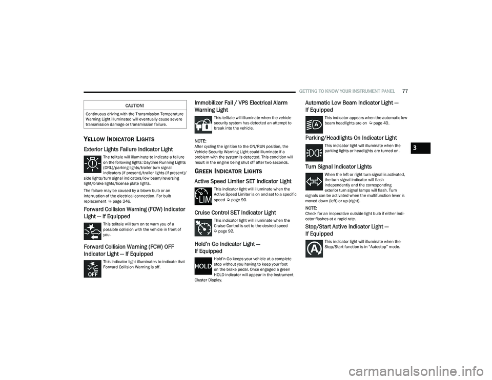
The telltale will illuminate to indicate a failure
on the following lights: Daytime Running Lights
(DRL)/parking lights/trailer turn signal
indicators (if present)/trailer lights (if present)/
side lights/turn signal indicators/low beam/reversing
light/brake lights/license plate lights.
The failure may be caused by a blown bulb or an
interruption of the electrical connection. For bulb
replacement
Úpage 246.
Forward Collision Warning (FCW) Indicator
Light — If Equipped
This telltale will turn on to warn you of a
possible collision with the vehicle in front of
you.
Forward Collision Warning (FCW) OFF
Indicator Light — If Equipped
This indicator light illuminates to indicate that
Forward Collision Warning is off.
Immobilizer Fail / VPS Electrical Alarm
Warning Light
This telltale will illuminate when the vehicle
security system has detected an attempt to
break into the vehicle.
NOTE:After cycling the ignition to the ON/RUN position, the
Vehicle Security Warning Light could illuminate if a
problem with the system is detected. This condition will
result in the engine being shut off after two seconds.
GREEN INDICATOR LIGHTS
Active Speed Limiter SET Indicator Light
This indicator light will illuminate when the
Active Speed Limiter is on and set to a specific
speed
Úpage 90.
Cruise Control SET Indicator Light
This indicator light will illuminate when the
Cruise Control is set to the desired speed
Úpage 92.
Hold’n Go Indicator Light —
If Equipped
Hold’n Go keeps your vehicle at a complete
stop without you having to keep your foot
on the brake pedal. Once engaged a green
HOLD indicator will appear in the Instrument
Cluster Display.
Automatic Low Beam Indicator Light —
If Equipped
This indicator appears when the automatic low
beam headlights are on Úpage 40.
Parking/Headlights On Indicator Light
This indicator light will illuminate when the
parking lights or headlights are turned on.
Turn Signal Indicator Lights
When the left or right turn signal is activated,
the turn signal indicator will flash
independently and the corresponding
exterior turn signal lamps will flash. Turn
signals can be activated when the multifunction lever is
moved down (left) or up (right).
NOTE:Check for an inoperative outside light bulb if either indi -
cator flashes at a rapid rate.
Stop/Start Active Indicator Light —
If Equipped
This indicator light will illuminate when the
Stop/Start function is in “Autostop” mode.
CAUTION!
Continuous driving with the Transmission Temperature
Warning Light illuminated will eventually cause severe
transmission damage or transmission failure.
3
23_GG_OM_EN_USC_t.book Page 77
Page 91 of 288
STARTING AND OPERATING89
If the “POWER STEERING SYSTEM HOT -
PERFORMANCE MAY BE LIMITED” message
and a steering wheel icon display on the
instrument cluster, it indicates that extreme
steering maneuvers may have occurred, which caused an
over temperature condition in the electric power steering
system. You will lose power steering assistance
momentarily until the over temperature condition no
longer exists. Once driving conditions are safe, pull over
and let the vehicle idle for a few moments until the light
turns off
Úpage 66.
NOTE:
Even if the power steering system is no longer opera -
tional, it is still possible to steer the vehicle. Under
these conditions there will be a substantial increase in
steering effort, especially at low speeds and during
parking maneuvers.
If the condition persists, see an authorized dealer for
service.
STOP/START SYSTEM — IF EQUIPPED
The Stop/Start function is designed to reduce fuel
consumption. The system will stop the engine
automatically during a vehicle stop if the required
conditions are met. Releasing the brake pedal or pressing
the accelerator pedal will automatically restart the engine.
This vehicle has been upgraded with a heavy-duty starter,
enhanced battery, and other upgraded engine parts, to
handle the additional engine starts.
AUTOSTOP MODE
The Stop/Start feature is enabled after every normal
customer engine start. At that time, the system will go into
STOP/START READY.
To Activate The Autostop Mode, The Following Must Occur:
The system must be in STOP/START READY state. A
“STOP/START READY” message will be displayed in the
instrument cluster display within the Stop/Start
section
Úpage 66.
The vehicle must be completely stopped.
The gear selector must be in a forward gear and the
brake pedal pressed.
The engine will shut down, the tachometer will move to the
zero position, and the Stop/Start telltale will illuminate
indicating you are in Autostop. Customer settings will be
maintained upon return to an engine-running condition.
POSSIBLE REASONS THE ENGINE DOES
N
OT AUTOSTOP
Prior to engine shut down, the system will check many
safety and comfort conditions to see if they are fulfilled.
Detailed information about the operation of the Stop/Start
system may be viewed in the instrument cluster display
Stop/Start Screen. In the following situations the engine
will not stop:
Driver’s seat belt is not buckled.
Driver’s door is not closed.
Battery temperature is too warm or cold.
Battery charge is low.
The vehicle is on a steep grade.
Cabin heating or cooling is in process and an accept -
able cabin temperature has not been achieved.
HVAC is set to full defrost mode at a high blower speed.
HVAC is set to MAX A/C.
Engine has not reached normal operating temperature.
The transmission is not in a forward gear.
Hood is open.
Brake pedal is not pressed with sufficient pressure.
Accelerator pedal input.
Engine temperature is too high.
5 mph (8 km/h) threshold has not been achieved from
previous Autostop.
Steering angle beyond threshold.
Adaptive Cruise Control is on and speed is set.
It may be possible for the vehicle to be driven several
times without the Stop/Start system going into a STOP/
START READY state under more extreme conditions of the
items listed previously.
4
23_GG_OM_EN_USC_t.book Page 89
Page 93 of 288
STARTING AND OPERATING91
NOTE:
The Mode button also activates the Adaptive Cruise
Control (ACC) system. Pushing the Mode button will
switch between activating the Active Speed Limiter or
the Adaptive Cruise Control systems. They cannot be
active at the same time.
The Active Speed Limiter can be set while the vehicle is
in motion, or with the gear selector in the PARK posi -
tion.
ACTIVATION
To activate the feature, push the Mode button located on
the left side of the steering wheel. A white indicator light in
the instrument cluster display to signal that Active Speed
Limiter has been enabled.
After the Active Speed Limiter system is enabled, activate
the system by setting the speed limit of the vehicle by
pushing the SET switch upward or downward.
Pushing the SET switch upward or downward to the first
detent, and releasing, will result in a 1 mph (1 km/h)
speed adjustment. Each subsequent movement of the
switch to the first detent will result in an adjustment of
1 mph (1 km/h).
If the switch is pushed upward or downward briefly to
the second detent, the set speed will adjust in 5 mph
(10 km/h) increments. The new set speed is reflected in
the instrument cluster display. If the switch is held upward or downward, the set speed
will continue to adjust until the switch is released.
NOTE:
Once the speed as been set, the indicator light in the
instrument cluster display will change to green.
If Adaptive Cruise Control (ACC) or the Active Speed
Limiter is active when the ignition is placed in the
OFF position, it will remain activated when the vehicle
is started again.
ACC will be unavailable while the Active Speed Limiter
is in use.
EXCEEDING THE SET SPEED
By fully pressing the accelerator pedal, the programmed
maximum speed can be exceeded while the device is
active.
In the event that the Active Speed Limiter set value is
exceeded manually with a driver acceleration, an audible
chime will sound. The indicator light will flash rapidly, and
a message will appear in the instrument cluster display.
The feature will remain disabled until the vehicle speed
drops below the set Active Speed Limiter value, where it
will reactivate automatically.
NOTE:While driving at a higher speed than previously set, the set
limit can be updated by pushing the SET switch upward or
downward to the new desired speed.
DEACTIVATION
To turn off Active Speed Limiter, push the Mode button
again. The indicator light in the instrument cluster display
will no longer be illuminated to confirm that the feature
has been turned off, and Adaptive Cruise Control will be
active.
The Active Speed Limiter can be deactivated by pressing
the CANC button. In this case, the system is not completely
turned off, and the driver can reactivate the Active Speed
Limiter by pressing the RES button to the previously set
speed.
INTELLIGENT SPEED ASSIST (ISA) —
IF EQUIPPED
The Intelligent Speed Assist (ISA) system
combines the Active Speed Limiter and
Traffic Sign Recognition (TSR) systems to
automatically adjust the maximum speed of
the vehicle based on detected speed limit signs.
When the ISA system is activated, the maximum speed of
the vehicle will be adjusted according to the detected
traffic signs depending on the Sign Capture Mode selected
within Uconnect Settings
Úpage 130.
4
23_GG_OM_EN_USC_t.book Page 91
Page 94 of 288
92STARTING AND OPERATING
ACTIVATION
To activate the feature, make sure the Traffic Sign
Recognition (TSR), and Intelligent Speed Assist (ISA) systems
are both enabled within Uconnect Settings
Ú
page 130, then
activate the Active Speed Limiter system by pushing the Mode
button located on the left of the steering wheel.
The white ISA indicator light in the instrument cluster
display will illuminate to signal that the system has been
enabled, but not yet detected a speed limit sign.
NOTE:Adaptive Cruise Control will be unavailable while the
ISA system is in use.
SIGN CAPTURE MODES
The way in which the ISA system sets a new maximum
vehicle speed depends on the Sign Capture Mode set
within the Uconnect system. When a new maximum speed
limit is set, the ISA indicator light in the instrument cluster
display will change from white to green.
Confirmation Mode
When Confirmation Mode is selected, and the Traffic Sign
Recognition (TSR) system detects a new speed limit sign,
the driver will confirm this new speed by pushing the
SET switch upward briefly, then releasing. This
confirmation of the new speed must be done within
five seconds of a newly detect speed limit sign being
shown in the instrument cluster display. Automatic Mode
When Automatic Mode is selected, the ISA system will
automatically adjust the maximum vehicle speed when
the TSR system detects a new speed limit sign. The new
speed is shown in the instrument cluster display.
The driver can reject this new speed by pushing the SET
switch upward briefly, then releasing within five seconds
of the new speed limit sign being detected and the speed
being adjusted.
NOTE:If a newly detected speed limit sign indicates a speed
higher or lower than the current maximum speed limit of
the Active Speed Limiter system, a message along with an
up arrow or a down arrow will appear in the instrument
cluster display to alert the driver.
EXCEEDING THE SET SPEED
By fully pressing the accelerator pedal, the maximum set
speed of the vehicle can be exceeded while the system is
active.
When the maximum set speed is exceeded, the green
indicator light on the instrument cluster display will blink
until the accelerator pedal is released and the vehicle
speed drops below the previously set maximum vehicle
speed. The ISA system will then resume normal operation.
DEACTIVATION
The ISA system will deactivate in the following situations:
When the Mode button is pushed again
When the TSR system is deactivated
When the TSR system cannot detect/display any speed
limit
When the TSR system detects the end of the speed
limit zone
CRUISE CONTROL SYSTEMS
Your vehicle is equipped with the Adaptive Cruise Control
(ACC) system. ACC will adjust the vehicle speed up to the
preset speed to maintain a distance with the vehicle
ahead.
NOTE:If Active Speed Limiter is enabled, Adaptive Cruise Control
will be unavailable, and vice versa.
ADAPTIVE CRUISE CONTROL (ACC)
Adaptive Cruise Control (ACC) increases the driving
convenience provided by Cruise Control while traveling on
highways and major roadways. However, it is not a safety
system and not designed to prevent collisions.
23_GG_OM_EN_USC_t.book Page 92
Page 95 of 288
STARTING AND OPERATING93
(Continued)
ACC will allow you to keep Cruise Control engaged in light
to moderate traffic conditions without the constant need
to reset your speed. ACC utilizes a radar sensor and a
forward facing camera designed to detect a vehicle
directly ahead of you to maintain a set speed.
NOTE:
If the ACC sensor detects a vehicle ahead, ACC will
apply limited braking or accelerate (not to exceed the
original set speed) automatically to maintain a preset
following distance, while matching the speed of the
vehicle ahead.
Any chassis/suspension or tire size modifications to
the vehicle will affect the performance of the Adaptive
Cruise Control and Forward Collision Warning system.
Adaptive Cruise Control (ACC) Operation
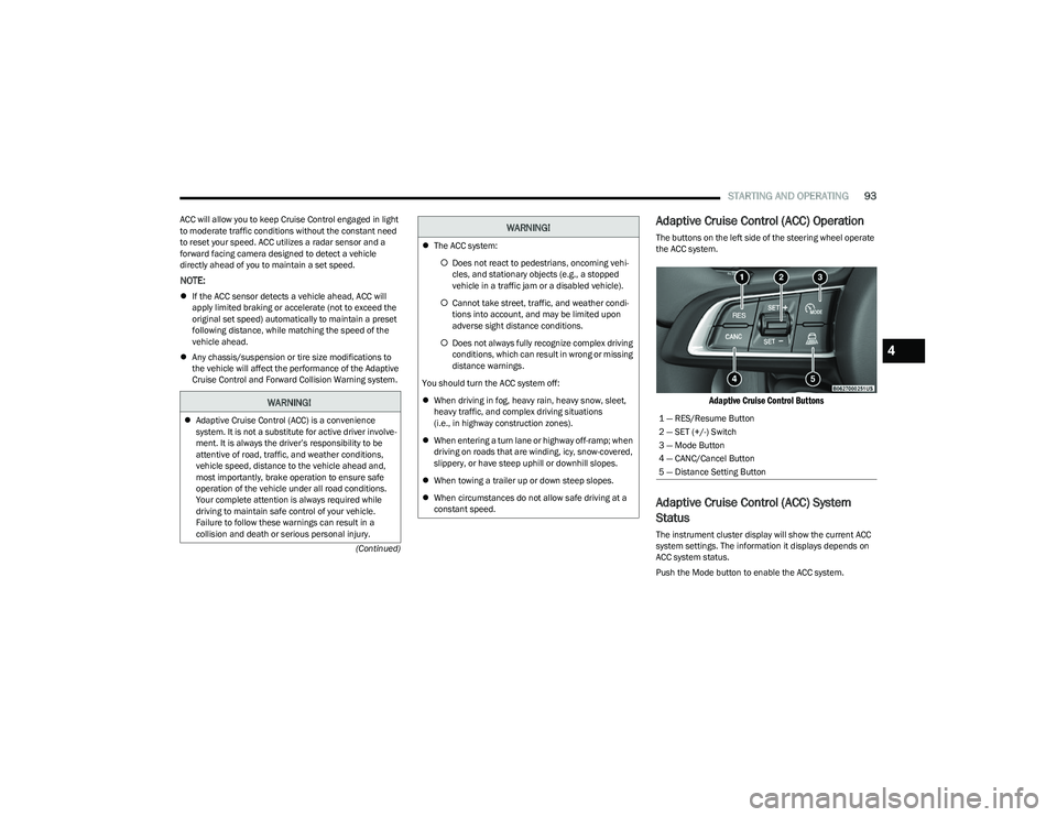
The buttons on the left side of the steering wheel operate
the ACC system.
Adaptive Cruise Control Buttons
Adaptive Cruise Control (ACC) System
Status
The instrument cluster display will show the current ACC
system settings. The information it displays depends on
ACC system status.
Push the Mode button to enable the ACC system.
WARNING!
Adaptive Cruise Control (ACC) is a convenience
system. It is not a substitute for active driver involve -
ment. It is always the driver’s responsibility to be
attentive of road, traffic, and weather conditions,
vehicle speed, distance to the vehicle ahead and,
most importantly, brake operation to ensure safe
operation of the vehicle under all road conditions.
Your complete attention is always required while
driving to maintain safe control of your vehicle.
Failure to follow these warnings can result in a
collision and death or serious personal injury.
The ACC system:
Does not react to pedestrians, oncoming vehi -
cles, and stationary objects (e.g., a stopped
vehicle in a traffic jam or a disabled vehicle).
Cannot take street, traffic, and weather condi -
tions into account, and may be limited upon
adverse sight distance conditions.
Does not always fully recognize complex driving
conditions, which can result in wrong or missing
distance warnings.
You should turn the ACC system off:
When driving in fog, heavy rain, heavy snow, sleet,
heavy traffic, and complex driving situations
(i.e., in highway construction zones).
When entering a turn lane or highway off-ramp; when
driving on roads that are winding, icy, snow-covered,
slippery, or have steep uphill or downhill slopes.
When towing a trailer up or down steep slopes.
When circumstances do not allow safe driving at a
constant speed.
WARNING!
1 — RES/Resume Button
2 — SET (+/-) Switch
3 — Mode Button
4 — CANC/Cancel Button
5 — Distance Setting Button
4
23_GG_OM_EN_USC_t.book Page 93
Page 96 of 288
94STARTING AND OPERATING
Adaptive Cruise Control Off
When ACC is deactivated, all ACC visualizations will not be
shown in the instrument cluster display.
Adaptive Cruise Control Ready
When ACC is activated, but the vehicle speed setting has
not been selected, the white ACC icon will illuminate above
dashes in place of a speed in the instrument cluster
display.
Adaptive Cruise Control Set
When the vehicle has reached the desired speed, push
the SET switch up or down briefly, then release. When the
ACC speed is set, the green ACC icon over the set speed
will illuminate in the instrument cluster display.
When the ACC menu screen is not being viewed in the
instrument cluster display, a green triangle will illuminate
on the speedometer at the location of the set speed.
NOTE:If the ACC system is canceled or paused, the triangle on
the speedometer will change to white, indicating the
saved set speed for when the RES button pushed.
Activating Adaptive Cruise Control (ACC)
The minimum set speed for the ACC system is 19 mph
(30 km/h).
NOTE:You cannot engage ACC under the following conditions:
When the brakes are applied
When the parking brake is applied
When the gear selector is in PARK, REVERSE or
NEUTRAL
When the vehicle speed is below the minimum speed
range
When the brakes are overheated
When the driver’s door is open at low speeds
When the driver’s seat belt is unbuckled at low speeds
When there is a stationary vehicle in front of your
vehicle in close proximity
To Activate/Deactivate
Push and release the Mode button located on the left side
of the steering wheel to activate ACC. Then proceed to
setting the desired speed as described in the next section.
NOTE:Active Speed Limiter will be unavailable while ACC is in
use.
To turn the system off, push and release the Mode button
again. At this time, the system will turn off and Active
Speed Limiter will be active.
The system will also turn off during any of the conditions
listed in “To Turn Off”
Úpage 95.
To Set A Desired Speed
When the vehicle has reached the desired speed, push
the SET switch up or down briefly, then release. The
instrument cluster display will show the set speed.
If ACC is set when the vehicle speed is
below
19 mph
(30 km/h), the set speed will default to 19 mph (30 km/h).
If either system is set when the vehicle speed is above
19 mph (30 km/h), the set speed shall be the current speed of the vehicle.
NOTE:
Keeping your foot on the accelerator pedal can cause
the vehicle to continue to accelerate beyond the set
speed.
If you continue to accelerate beyond the set speed
while ACC is enabled, the system will not be controlling
the distance between your vehicle and the vehicle
ahead. The vehicle speed will only be determined by
the position of the accelerator pedal.
WARNING!
Leaving the Adaptive Cruise Control (ACC) system on
when not in use is dangerous. You could accidentally
set the system or cause it to go faster than you want.
You could lose control and have a collision. Always leave
the system off when you are not using it.
WARNING!
If the Active Speed Limiter is active, the system will not
react to vehicles ahead. In addition, the proximity
warning does not activate and no alarm will sound even
if you are too close to the vehicle ahead since neither
the presence of the vehicle ahead nor the
vehicle-to-vehicle distance is detected. Be sure to
maintain a safe distance between your vehicle and the
vehicle ahead. Always be aware which mode is
selected.
23_GG_OM_EN_USC_t.book Page 94
Page 98 of 288
96STARTING AND OPERATING
TO ACCELERATE FOR PASSING
While the Cruise Control is set, press the accelerator to
pass as you would normally. When the pedal is released,
the vehicle will return to the set speed.
Using Cruise Control On Hills
The transmission may downshift on hills to maintain the
vehicle set speed.
The Cruise Control system maintains speed up and down
hills. A slight speed change on moderate hills is normal.
On steep hills, a greater speed loss or gain may occur so it
may be preferable to drive without Cruise Control.
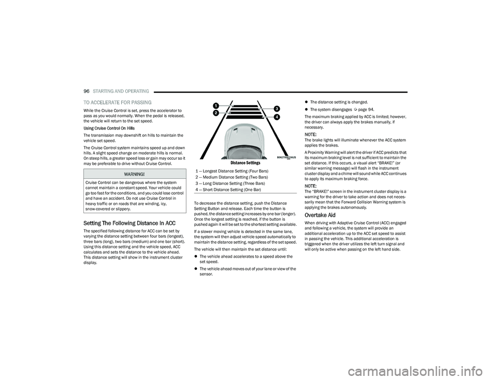
Setting The Following Distance In ACC
The specified following distance for ACC can be set by
varying the distance setting between four bars (longest),
three bars (long), two bars (medium) and one bar (short).
Using this distance setting and the vehicle speed, ACC
calculates and sets the distance to the vehicle ahead.
This distance setting will show in the instrument cluster
display.
Distance Settings
To decrease the distance setting, push the Distance
Setting Button and release. Each time the button is
pushed, the distance setting increases by one bar (longer).
Once the longest setting is reached, if the button is
pushed again it will be set to the shortest setting available.
If a slower moving vehicle is detected in the same lane,
the system will then adjust vehicle speed automatically to
maintain the distance setting, regardless of the set speed.
The vehicle will then maintain the set distance until:
The vehicle ahead accelerates to a speed above the
set speed.
The vehicle ahead moves out of your lane or view of the
sensor.
The distance setting is changed.
The system disengages
Úpage 94.
The maximum braking applied by ACC is limited; however,
the driver can always apply the brakes manually, if
necessary.
NOTE:The brake lights will illuminate whenever the ACC system
applies the brakes.
A Proximity Warning will alert the driver if ACC predicts that
its maximum braking level is not sufficient to maintain the
set distance. If this occurs, a visual alert “BRAKE!” (or
similar warning message) will flash in the instrument
cluster display and a chime will sound while ACC continues
to apply its maximum braking force.
NOTE:The “BRAKE!” screen in the instrument cluster display is a
warning for the driver to take action and does not neces -
sarily mean that the Forward Collision Warning system is
applying the brakes autonomously.
Overtake Aid
When driving with Adaptive Cruise Control (ACC) engaged
and following a vehicle, the system will provide an
additional acceleration up to the ACC set speed to assist
in passing the vehicle. This additional acceleration is
triggered when the driver utilizes the left turn signal and
will only be active when passing on the left hand side.
WARNING!
Cruise Control can be dangerous where the system
cannot maintain a constant speed. Your vehicle could
go too fast for the conditions, and you could lose control
and have an accident. Do not use Cruise Control in
heavy traffic or on roads that are winding, icy,
snow-covered or slippery.
1 — Longest Distance Setting (Four Bars)
2 — Medium Distance Setting (Two Bars)
3 — Long Distance Setting (Three Bars)
4 — Short Distance Setting (One Bar)
23_GG_OM_EN_USC_t.book Page 96
Page 102 of 288
100STARTING AND OPERATING
(Continued)
INDICATIONS ON THE DISPLAY
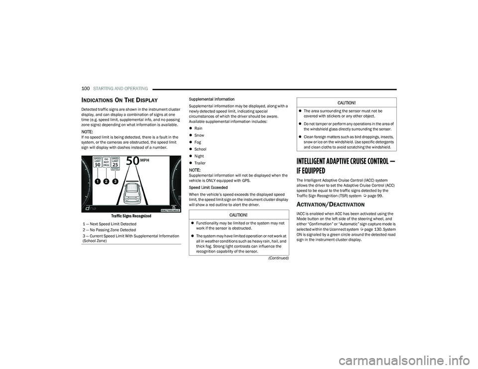
Detected traffic signs are shown in the instrument cluster
display, and can display a combination of signs at one
time (e.g. speed limit, supplemental info, and no passing
zone signs) depending on what information is available.
NOTE:If no speed limit is being detected, there is a fault in the
system, or the cameras are obstructed, the speed limit
sign will display with dashes instead of a number.
Traffic Signs Recognized
Supplemental Information
Supplemental information may be displayed, along with a
newly detected speed limit, indicating special
circumstances of which the driver should be aware.
Available supplemental information includes:
Rain
Snow
Fog
School
Night
Trailer
NOTE:Supplemental information will not be displayed when the
vehicle is ONLY equipped with GPS.
Speed Limit Exceeded
When the vehicle’s speed exceeds the displayed speed
limit, the speed limit sign on the instrument cluster display
will show a red outline to alert the driver.
INTELLIGENT ADAPTIVE CRUISE CONTROL —
IF EQUIPPED
The Intelligent Adaptive Cruise Control (IACC) system
allows the driver to set the Adaptive Cruise Control (ACC)
speed to be equal to the traffic signs detected by the
Traffic Sign Recognition (TSR) system
Úpage 99.
ACTIVATION/DEACTIVATION
IACC is enabled when ACC has been activated using the
Mode button on the left side of the steering wheel, and
either “Confirmation” or “Automatic” sign capture mode is
selected within the Uconnect system
Úpage 130. System
ON is signaled by a green circle around the detected road
sign in the instrument cluster display.
1 — Next Speed Limit Detected
2 — No Passing Zone Detected
3 — Current Speed Limit With Supplemental Information
(School Zone)
CAUTION!
Functionality may be limited or the system may not
work if the sensor is obstructed.
The system may have limited operation or not work at
all in weather conditions such as heavy rain, hail, and
thick fog. Strong light contrasts can influence the
recognition capability of the sensor.
The area surrounding the sensor must not be
covered with stickers or any other object.
Do not tamper or perform any operations in the area of
the windshield glass directly surrounding the sensor.
Clean foreign matters such as bird droppings, insects,
snow or ice on the windshield. Use specific detergents
and clean cloths to avoid scratching the windshield.
CAUTION!
23_GG_OM_EN_USC_t.book Page 100