brakes DODGE HORNET 2023 Owners Manual
[x] Cancel search | Manufacturer: DODGE, Model Year: 2023, Model line: HORNET, Model: DODGE HORNET 2023Pages: 288, PDF Size: 14.2 MB
Page 82 of 288
80
STARTING AND OPERATING
STARTING THE ENGINE
Before starting your vehicle, adjust your seat, adjust both
inside and outside mirrors, and fasten your seat belts.Start the engine with the gear selector in the NEUTRAL or
PARK position. Apply the brake before shifting to any
driving range.
NORMAL STARTING
Place the ignition switch in the START position and release
when the engine starts. If the engine fails to start within
10 seconds, place the ignition switch in the OFF position,
wait 10 to 15 seconds, then repeat the “Normal Starting”
procedure.
Tip Start Feature
Place the ignition switch in the START position and release
it as soon as the starter engages. The starter motor will
continue to run, and will automatically disengage itself
when the engine is running. If the engine fails to start,
place the ignition switch in the OFF position, wait 10 to
15 seconds, then repeat the “Normal Starting” procedure.
Automatic Transmission
The gear selector must be in the NEUTRAL or PARK
position before you can start the engine. Apply the brakes
before shifting into any driving gear.Keyless Enter ’n Go™ Functions — Using The ENGINE
START/STOP Button
1. The transmission must be in PARK or NEUTRAL.
2. Press and hold the brake pedal while pushing the
ENGINE START/STOP button once.
3. The system starts the vehicle. If the vehicle fails to start, the starter will disengage automatically after
10 seconds.
4. If you wish to stop the cranking of the engine prior to the engine starting, push the ENGINE START/STOP
button again.
WARNING!
When exiting the vehicle, always remove the key fob
from the vehicle and lock your vehicle.
Never leave children alone in a vehicle, or with
access to an unlocked vehicle.
Allowing children to be in a vehicle unattended is
dangerous for a number of reasons. A child or others
could be seriously or fatally injured. Children should
be warned not to touch the parking brake, brake
pedal or the transmission gear selector.
Do not leave the key fob in or near the vehicle, or in
a location accessible to children, and do not leave
the ignition of a vehicle equipped with Keyless
Enter ’n Go™ in the ON/RUN position. A child could
operate power windows, other controls, or move the
vehicle.
Do not leave children or animals inside parked
vehicles in hot weather. Interior heat buildup may
cause serious injury or death.
CAUTION!
Damage to the transmission may occur if the following
precautions are not observed:
Do not shift between PARK, REVERSE, NEUTRAL, or
DRIVE when the engine is above idle speed.
Shift into or out of PARK or REVERSE only after the
vehicle has come to a complete stop.
Before shifting into any gear, make sure your foot is
firmly on the brake pedal.
23_GG_OM_EN_USC_t.book Page 80
Page 85 of 288
STARTING AND OPERATING83
(Continued)
NOTE:The EPB Warning Light will illuminate if the EPB switch is
held for longer than 60 seconds in either the released or
applied position. The light will extinguish upon releasing
the switch.
If the Auto Park Brake feature is enabled, the parking
brake will automatically engage whenever the
transmission is placed into PARK. If your foot is on the
brake pedal, you may notice a small amount of brake
pedal movement while the parking brake is engaging.
The parking brake will release automatically when the
ignition switch is ON/RUN, the transmission is in DRIVE or
REVERSE, the driver’s seat belt is buckled, and an attempt
is made to drive away.
To release the parking brake manually, the ignition switch
must be in the ON/RUN position. Put your foot on the
brake pedal, then push the EPB switch down momentarily.
You may hear a sound from the back of the car while the
parking brake disengages. You may also notice a small
amount of movement in the brake pedal. Once the parking
brake is fully disengaged, the Brake Warning Light in the
instrument cluster and the LED indicator on the switch will
extinguish.
NOTE:When parking on a hill, it is important to turn the front
wheels toward the curb on a downhill grade and away from
the curb on an uphill grade. Apply the parking brake before
placing the gear selector in PARK, otherwise the load on
the transmission locking mechanism may make it difficult to move the gear selector out of PARK. The parking brake
should always be applied whenever the driver is not in the
vehicle.
If exceptional circumstances should make it necessary to
engage the parking brake while the vehicle is in motion,
maintain upward pressure on the EPB switch for as long as
engagement is desired. The Brake Warning Light will
illuminate, and a continuous chime will sound. The rear
stop lamps will also be illuminated automatically while the
vehicle remains in motion.
To disengage the parking brake while the vehicle is in
motion, release the switch. If the vehicle is brought to a
complete stop using the parking brake, when the vehicle
reaches approximately 3 mph, (5 km/h) the parking brake
will remain engaged.
WARNING!
Do not rely on the parking brake to operate effec -
tively if the rear brakes have been immersed in water
or mud.
Never use the PARK position as a substitute for the
parking brake. Always apply the parking brake fully
when parked to guard against vehicle movement and
possible injury or damage.
When leaving the vehicle, always remove the key fob
from the ignition and lock your vehicle.
Never leave children alone in a vehicle, or with
access to an unlocked vehicle. Allowing children to
be in a vehicle unattended is dangerous for a
number of reasons. A child or others could be seri -
ously or fatally injured. Children should be warned
not to touch the parking brake, brake pedal or the
gear selector.
Do not leave the key fob in or near the vehicle, or in
a location accessible to children, and do not leave
the ignition of a vehicle equipped with Keyless
Enter ’n Go™ in the ACC or ON/RUN position. A child
could operate power windows, other controls, or
move the vehicle.
Be sure the parking brake is fully disengaged before
driving; failure to do so can lead to brake failure and
a collision.
Always fully apply the parking brake when leaving
your vehicle, or it may roll and cause damage or
injury. Also be certain to leave the transmission in
PARK. Failure to do so may allow the vehicle to roll
and cause damage or injury.
CAUTION!
If the Brake System Warning Light remains on with the
parking brake released, a brake system malfunction is
indicated. Have the brake system serviced by an
authorized dealer immediately.
WARNING!
4
23_GG_OM_EN_USC_t.book Page 83
Page 86 of 288
84STARTING AND OPERATING
In the unlikely event of a malfunction of the EPB system, a
yellow EPB Warning Light will illuminate. This may be
accompanied by the Brake Warning Light flashing. In this
event, urgent service of the EPB system is required. Do not
rely on the parking brake to hold the vehicle stationary.
Auto Park Brake
The EPB can be programmed to be applied automatically
whenever the vehicle speed is below 1.9 mph (3 km/h)
and the transmission is placed in PARK. Auto Park Brake
is enabled and disabled by customer selection through the
Customer Programmable Features section of the
Uconnect Settings
Úpage 130.
Any single Auto Park Brake application can be bypassed by
pushing the EPB switch to the release position while the
transmission is placed in PARK and the ignition is in the
ON/RUN position.
SafeHold
SafeHold is a safety feature of the EPB system that will
engage the parking brake automatically if the vehicle is
left unsecured while the ignition switch is in ON/RUN. For automatic transmissions, the EPB will automatically
engage if all of the following conditions are met:
Vehicle speed is below 1.9 mph (3 km/h).
There is no attempt to press the brake pedal and
accelerator pedal.
The seat belt is unbuckled.
The driver’s door is open.
The vehicle is not in the PARK position.
SafeHold can be temporarily bypassed by pushing the EPB
switch while the driver’s door is open and the brake pedal
is pressed. Once manually bypassed, SafeHold will be
enabled again once the vehicle reaches 12 mph
(20 km/h) or the ignition is turned to the OFF position and
back to ON/RUN again.
Hold ‘N Go— If Equipped
Hold ‘N Go is a comfort feature that allows the driver to
remove their foot from the brake pedal once the vehicle
has come to a stop. The vehicle must be held at a
standstill for a predetermined amount of time by hydraulic
braking. The EPB will then engage and continue to hold
the vehicle at a stop until the driver applies the accelerator
pedal. Hold ‘N Go is enabled and disabled by customer
selection through the customer programmable features
section of the Uconnect Settings
Úpage 130.
The following conditions must be met for Hold ‘N Go to
activate:
Driver’s door is closed
Driver's seat belt is fastened
Vehicle is at a standstill
Forward gear is selected
EPB is not applied
Brake Service Mode
We recommend having your brakes serviced by an
authorized dealer.
You should only make repairs for which you have the
knowledge and the right equipment. You should only enter
Brake Service Mode during brake service.
When servicing your rear brakes, it may be necessary for
you or your technician to push the rear piston into the rear
caliper bore. With the EPB system, this can only be done
after retracting the EPB actuator. The actuator retraction
can be done easily by entering Brake Service Mode
through the Uconnect Settings in your vehicle. This
menu-based system will guide you through the steps
necessary to retract the EPB actuator in order to perform
rear brake service.
Brake Service Mode has requirements that must be met in
order to be activated:
The vehicle must be at a standstill.
The parking brake must be disabled.
The transmission must be in PARK or NEUTRAL.
The EPB switch not activated.
The vehicle ignition in the ON/RUN position.
The brake pedal not pressed.
While in Service Mode, the EPB Warning Light will flash
continuously while the ignition switch is in ON/RUN.
NOTE:A dedicated message will appear in the instrument cluster
display if Brake Service Mode cannot be activated.
WARNING!
Driving the vehicle with the parking brake engaged, or
repeated use of the parking brake to slow the vehicle,
may cause serious damage to the brake system.
Be sure the parking brake is fully disengaged before
driving; failure to do so can lead to brake failure and
a collision.
23_GG_OM_EN_USC_t.book Page 84
Page 88 of 288
86STARTING AND OPERATING
IGNITION PARK INTERLOCK
This vehicle is equipped with an Ignition Park Interlock
which requires the transmission to be in PARK (P) before
the ignition can be turned to the OFF position. This helps
the driver avoid inadvertently leaving the vehicle without
placing the transmission in PARK. This system maintains
lock of the transmission in PARK whenever the ignition is
in the OFF position.
BRAKE/TRANSMISSION SHIFT
I
NTERLOCK (BTSI) SYSTEM
This vehicle is equipped with a BTSI that holds the
transmission gear selector in PARK (P) unless the brakes
are applied. To shift the transmission out of PARK, the
ignition must be in the ON/RUN position (whether the
engine is running or not), and the brake pedal must be
pressed. The brake pedal must also be pressed to shift
from NEUTRAL (N) into DRIVE (D) or REVERSE (R) when the
vehicle is stopped or moving at low speeds.
9-SPEED AUTOMATIC TRANSMISSION
The transmission gear range (PRND) is displayed both
beside the gear selector and in the instrument cluster.
To select a gear range, push the lock button on the gear
selector and move the selector rearward or forward. You
must also press the brake pedal to shift the transmission
out of PARK (P) (or NEUTRAL (N), when the vehicle is
stopped or moving at low speeds). Select the DRIVE (D)
range for normal driving.
NOTE:
The transmission electronics are self-calibrating;
therefore, the first few shifts on a new vehicle may be
somewhat abrupt. This is a normal condition, and
precision shifts will develop within a few hundred
miles (kilometers).
In the event of a mismatch between the gear selector
position and the actual transmission gear (for example,
driver selects REVERSE (R) while driving forward), the
position indicator will blink continuously until the
selector is returned to the proper position, or the
requested shift can be completed.
The electronically controlled transmission adapts its shift
schedule based on driver inputs, along with environmental
and road conditions.
The 9-speed transmission has been developed to meet
the needs of current and future FWD/AWD vehicles.
Software and calibration are refined to optimize the
customer’s driving experience and fuel economy. By
design, some vehicle and driveline combinations utilize
NINTH gear only in very specific driving situations and
conditions.
Only shift from DRIVE to PARK or REVERSE when the
accelerator pedal is released and the vehicle is stopped.
Be sure to keep your foot on the brake pedal when shifting
between these gears.
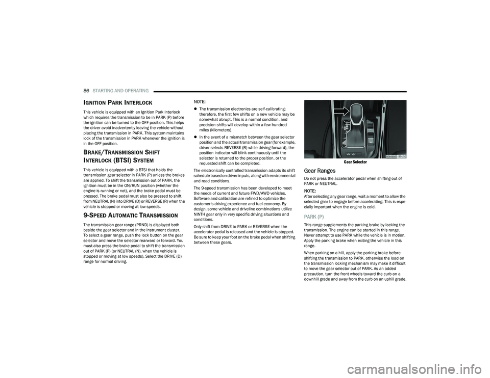
Gear Selector
Gear Ranges
Do not press the accelerator pedal when shifting out of
PARK or NEUTRAL.
NOTE:After selecting any gear range, wait a moment to allow the
selected gear to engage before accelerating. This is espe -
cially important when the engine is cold.
PARK (P)
This range supplements the parking brake by locking the
transmission. The engine can be started in this range.
Never attempt to use PARK while the vehicle is in motion.
Apply the parking brake when exiting the vehicle in this
range.
When parking on a hill, apply the parking brake before
shifting the transmission to PARK, otherwise the load on
the transmission locking mechanism may make it difficult
to move the gear selector out of PARK. As an added
precaution, turn the front wheels toward the curb on a
downhill grade and away from the curb on an uphill grade.
23_GG_OM_EN_USC_t.book Page 86
Page 96 of 288
94STARTING AND OPERATING
Adaptive Cruise Control Off
When ACC is deactivated, all ACC visualizations will not be
shown in the instrument cluster display.
Adaptive Cruise Control Ready
When ACC is activated, but the vehicle speed setting has
not been selected, the white ACC icon will illuminate above
dashes in place of a speed in the instrument cluster
display.
Adaptive Cruise Control Set
When the vehicle has reached the desired speed, push
the SET switch up or down briefly, then release. When the
ACC speed is set, the green ACC icon over the set speed
will illuminate in the instrument cluster display.
When the ACC menu screen is not being viewed in the
instrument cluster display, a green triangle will illuminate
on the speedometer at the location of the set speed.
NOTE:If the ACC system is canceled or paused, the triangle on
the speedometer will change to white, indicating the
saved set speed for when the RES button pushed.
Activating Adaptive Cruise Control (ACC)
The minimum set speed for the ACC system is 19 mph
(30 km/h).
NOTE:You cannot engage ACC under the following conditions:
When the brakes are applied
When the parking brake is applied
When the gear selector is in PARK, REVERSE or
NEUTRAL
When the vehicle speed is below the minimum speed
range
When the brakes are overheated
When the driver’s door is open at low speeds
When the driver’s seat belt is unbuckled at low speeds
When there is a stationary vehicle in front of your
vehicle in close proximity
To Activate/Deactivate
Push and release the Mode button located on the left side
of the steering wheel to activate ACC. Then proceed to
setting the desired speed as described in the next section.
NOTE:Active Speed Limiter will be unavailable while ACC is in
use.
To turn the system off, push and release the Mode button
again. At this time, the system will turn off and Active
Speed Limiter will be active.
The system will also turn off during any of the conditions
listed in “To Turn Off”
Úpage 95.
To Set A Desired Speed
When the vehicle has reached the desired speed, push
the SET switch up or down briefly, then release. The
instrument cluster display will show the set speed.
If ACC is set when the vehicle speed is
below
19 mph
(30 km/h), the set speed will default to 19 mph (30 km/h).
If either system is set when the vehicle speed is above
19 mph (30 km/h), the set speed shall be the current speed of the vehicle.
NOTE:
Keeping your foot on the accelerator pedal can cause
the vehicle to continue to accelerate beyond the set
speed.
If you continue to accelerate beyond the set speed
while ACC is enabled, the system will not be controlling
the distance between your vehicle and the vehicle
ahead. The vehicle speed will only be determined by
the position of the accelerator pedal.
WARNING!
Leaving the Adaptive Cruise Control (ACC) system on
when not in use is dangerous. You could accidentally
set the system or cause it to go faster than you want.
You could lose control and have a collision. Always leave
the system off when you are not using it.
WARNING!
If the Active Speed Limiter is active, the system will not
react to vehicles ahead. In addition, the proximity
warning does not activate and no alarm will sound even
if you are too close to the vehicle ahead since neither
the presence of the vehicle ahead nor the
vehicle-to-vehicle distance is detected. Be sure to
maintain a safe distance between your vehicle and the
vehicle ahead. Always be aware which mode is
selected.
23_GG_OM_EN_USC_t.book Page 94
Page 98 of 288
96STARTING AND OPERATING
TO ACCELERATE FOR PASSING
While the Cruise Control is set, press the accelerator to
pass as you would normally. When the pedal is released,
the vehicle will return to the set speed.
Using Cruise Control On Hills
The transmission may downshift on hills to maintain the
vehicle set speed.
The Cruise Control system maintains speed up and down
hills. A slight speed change on moderate hills is normal.
On steep hills, a greater speed loss or gain may occur so it
may be preferable to drive without Cruise Control.
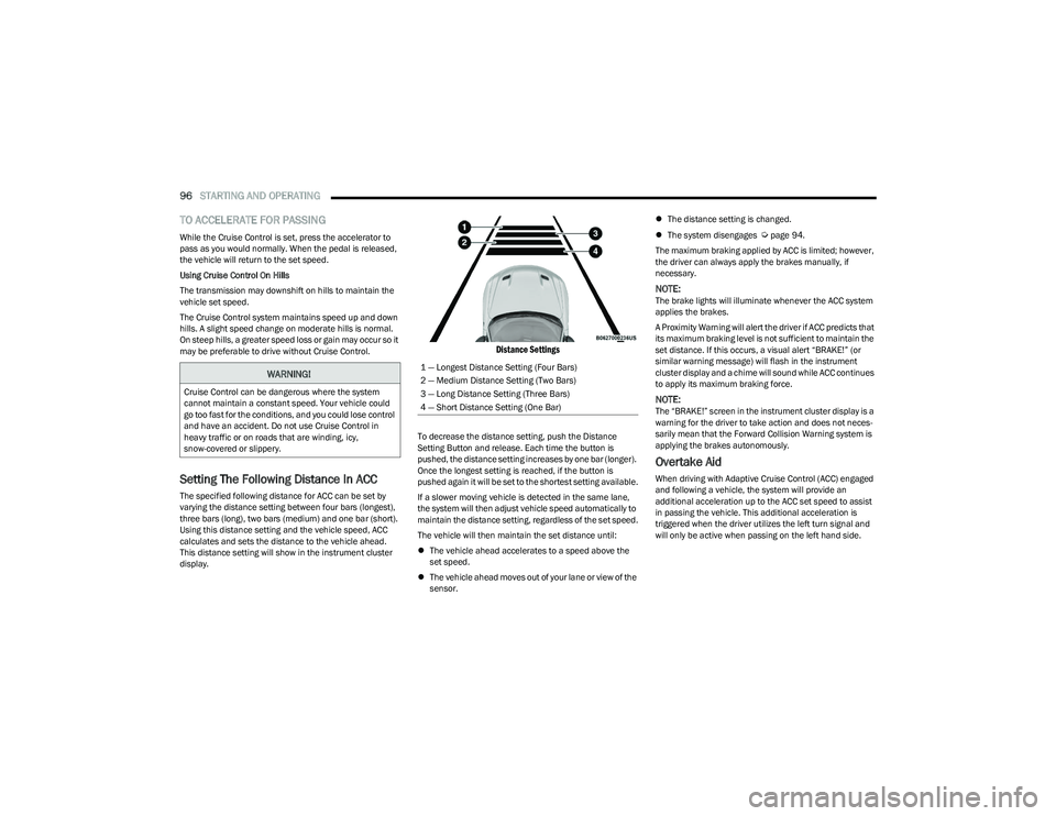
Setting The Following Distance In ACC
The specified following distance for ACC can be set by
varying the distance setting between four bars (longest),
three bars (long), two bars (medium) and one bar (short).
Using this distance setting and the vehicle speed, ACC
calculates and sets the distance to the vehicle ahead.
This distance setting will show in the instrument cluster
display.
Distance Settings
To decrease the distance setting, push the Distance
Setting Button and release. Each time the button is
pushed, the distance setting increases by one bar (longer).
Once the longest setting is reached, if the button is
pushed again it will be set to the shortest setting available.
If a slower moving vehicle is detected in the same lane,
the system will then adjust vehicle speed automatically to
maintain the distance setting, regardless of the set speed.
The vehicle will then maintain the set distance until:
The vehicle ahead accelerates to a speed above the
set speed.
The vehicle ahead moves out of your lane or view of the
sensor.
The distance setting is changed.
The system disengages
Úpage 94.
The maximum braking applied by ACC is limited; however,
the driver can always apply the brakes manually, if
necessary.
NOTE:The brake lights will illuminate whenever the ACC system
applies the brakes.
A Proximity Warning will alert the driver if ACC predicts that
its maximum braking level is not sufficient to maintain the
set distance. If this occurs, a visual alert “BRAKE!” (or
similar warning message) will flash in the instrument
cluster display and a chime will sound while ACC continues
to apply its maximum braking force.
NOTE:The “BRAKE!” screen in the instrument cluster display is a
warning for the driver to take action and does not neces -
sarily mean that the Forward Collision Warning system is
applying the brakes autonomously.
Overtake Aid
When driving with Adaptive Cruise Control (ACC) engaged
and following a vehicle, the system will provide an
additional acceleration up to the ACC set speed to assist
in passing the vehicle. This additional acceleration is
triggered when the driver utilizes the left turn signal and
will only be active when passing on the left hand side.
WARNING!
Cruise Control can be dangerous where the system
cannot maintain a constant speed. Your vehicle could
go too fast for the conditions, and you could lose control
and have an accident. Do not use Cruise Control in
heavy traffic or on roads that are winding, icy,
snow-covered or slippery.
1 — Longest Distance Setting (Four Bars)
2 — Medium Distance Setting (Two Bars)
3 — Long Distance Setting (Three Bars)
4 — Short Distance Setting (One Bar)
23_GG_OM_EN_USC_t.book Page 96
Page 100 of 288
98STARTING AND OPERATING
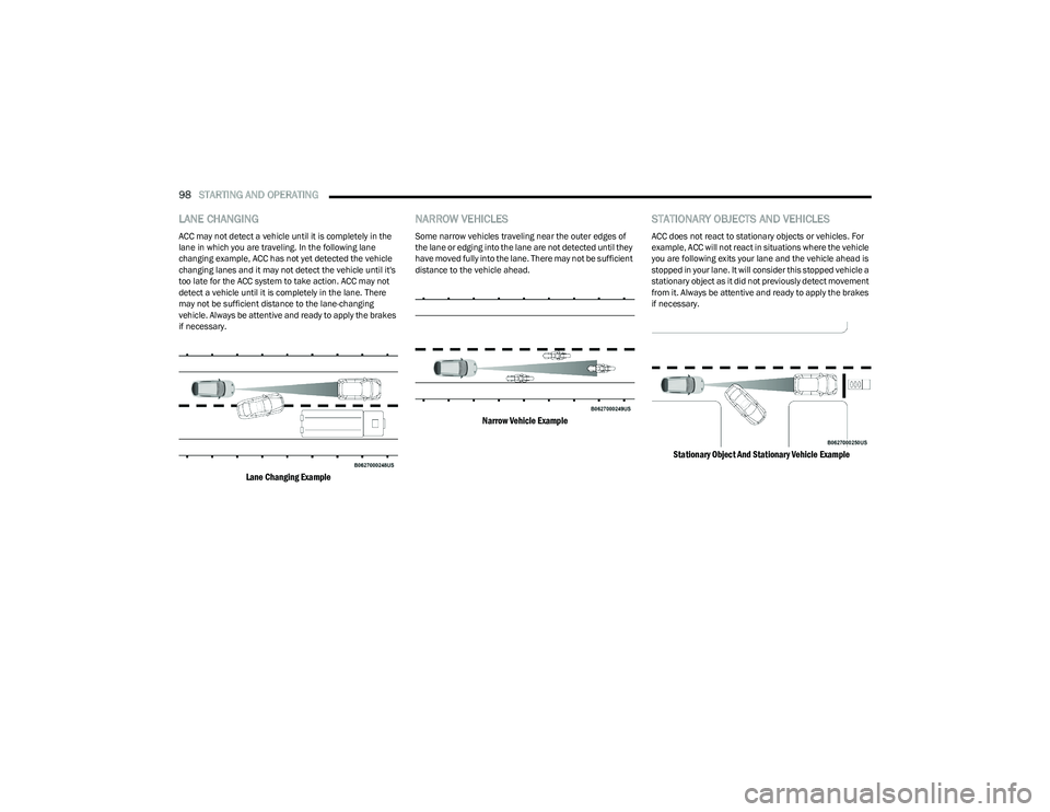
LANE CHANGING
ACC may not detect a vehicle until it is completely in the
lane in which you are traveling. In the following lane
changing example, ACC has not yet detected the vehicle
changing lanes and it may not detect the vehicle until it's
too late for the ACC system to take action. ACC may not
detect a vehicle until it is completely in the lane. There
may not be sufficient distance to the lane-changing
vehicle. Always be attentive and ready to apply the brakes
if necessary.
Lane Changing Example
NARROW VEHICLES
Some narrow vehicles traveling near the outer edges of
the lane or edging into the lane are not detected until they
have moved fully into the lane. There may not be sufficient
distance to the vehicle ahead.
Narrow Vehicle Example
STATIONARY OBJECTS AND VEHICLES
ACC does not react to stationary objects or vehicles. For
example, ACC will not react in situations where the vehicle
you are following exits your lane and the vehicle ahead is
stopped in your lane. It will consider this stopped vehicle a
stationary object as it did not previously detect movement
from it. Always be attentive and ready to apply the brakes
if necessary.
Stationary Object And Stationary Vehicle Example
23_GG_OM_EN_USC_t.book Page 98
Page 110 of 288
108STARTING AND OPERATING
(Continued)
Side Distance Warning Usage Precautions
Some conditions may influence the performance of the
Side Distance Warning system:
NOTE:
Ensure that the front and rear fascias/bumpers are
free of snow, ice, mud, dirt and debris to keep the
ParkSense system operating properly.
Construction equipment, large trucks, and other vibra -
tions could affect the performance of ParkSense.
ParkSense, when on, will reduce the volume of the
radio when it is sounding a tone.
Clean the ParkSense sensors regularly, taking care not
to scratch or damage them. The sensors must not be
covered with ice, snow, slush, mud, dirt or debris.
Failure to do so can result in the system not working
properly. The ParkSense system might not detect an
obstacle behind or in front of the fascia/bumper, or it
could provide a false indication that an obstacle is
behind or in front of the fascia/bumper.
The presence of a tow hook without a trailer may inter -
fere with the correct operation of the parking sensors.
Before using the ParkSense system, it is recom -
mended to remove the removable tow hook ball
assembly and any attachments from the vehicle when
it is not used for towing operations. If you leave the tow
hook fitted when not towing a trailer, the tow hook
could be detected as an obstacle by the sensors.
Contact your authorized dealer to update the
ParkSense system operations.
PARKSENSE ACTIVE PARK ASSIST SYSTEM —
IF EQUIPPED
The ParkSense Active Park Assist system is intended to
assist the driver during parallel, perpendicular, and
parallel park exit maneuvers by identifying a proper
parking space, providing audible/visual instructions, and
controlling the steering wheel. The ParkSense Active Park
Assist system is defined as “semi-automatic” since the
driver maintains control of the accelerator, gear selector
and brakes. Depending on the driver's parking maneuver
selection, the ParkSense Active Park Assist system is
capable of maneuvering a vehicle into a parallel or a
perpendicular parking space on either side (i.e., driver
side or passenger side), as well as exiting a parallel
parking space.
NOTE:
The driver is always responsible for controlling the
vehicle, responsible for any surrounding objects, and
must intervene as required.
The system is designed to assist the driver and not to
substitute the driver.
WARNING!
Drivers must be careful when backing up even when
using ParkSense. Always check carefully behind your
vehicle, look behind you, and be sure to check for
pedestrians, animals, other vehicles, obstructions,
and blind spots before backing up. You are respon -
sible for safety and must continue to pay attention to
your surroundings. Failure to do so can result in
serious injury or death.
Before using ParkSense, it is strongly recommended
that the ball mount and hitch ball assembly be
disconnected from the vehicle when the vehicle is
not used for towing. Failure to do so can result in
injury or damage to vehicles or obstacles because
the hitch ball will be much closer to the obstacle than
the rear fascia/bumper when the vehicle sounds the
continuous tone. Also, the sensors could detect the
ball mount and hitch ball assembly, depending on its
size and shape, giving a false indication that an
obstacle is behind the vehicle.
CAUTION!
ParkSense is only a parking aid and it is unable to
recognize every obstacle, including small obstacles.
Parking curbs might be temporarily detected or not
detected at all. Obstacles located above or below the
sensors will not be detected when they are in close
proximity.
The vehicle must be driven slowly when using
ParkSense in order to be able to stop in time when
an obstacle is detected. It is recommended that
the driver looks over his/her shoulder when using
ParkSense.
CAUTION!
23_GG_OM_EN_USC_t.book Page 108
Page 118 of 288
116STARTING AND OPERATING
CHANGING LANESENSE STATUS
The LaneSense system has settings to adjust the intensity
of the torque warning (low/med/high) and the warning
zone sensitivity (early/late) that you can configure through
the Uconnect system
Úpage 130.
NOTE:
When enabled the system operates above 37 mph
(60 km/h) and below 112 mph (180 km/h).
Use of the turn signal suppresses the warnings.
The system will not apply torque to the steering wheel
whenever a safety system engages (Anti-Lock Brakes,
Traction Control System, Electronic Stability Control,
Forward Collision Warning, etc.).
PARKVIEW REAR BACK UP CAMERA
The ParkView Rear Back Up Camera allows you to see an
on-screen image of the rear surroundings of your vehicle
whenever the gear selector is put into REVERSE. The
image will be displayed on the Navigation/Multimedia
radio display screen along with a caution note to
“Check Entire Surroundings” across the top of the screen.
After five seconds this note will disappear. The ParkView
camera is located on the rear of the vehicle above the rear
license plate. When the vehicle is shifted out of REVERSE with camera
delay turned off, the rear camera mode is exited and the
previous screen appears.
Manual Activation Of The Back Up Camera
1. Press the Controls button located in the Vehicle
Controls menu, or within the Apps drawer. This
button can also be configured as a shortcut on the
bottom of the Uconnect display.
2. Press the Back Up Camera button to turn the Rear View Camera system on.
NOTE:The ParkView Rear Back Up Camera has programmable
modes of operation that may be selected through the
Uconnect system
Úpage 130.
When the vehicle is shifted out of REVERSE with camera
delay turned off, the rear camera mode is exited and the
previous screen appears. When the vehicle is shifted out
of REVERSE with camera delay turned on, the camera
image will continue to be displayed for up to 10 seconds
unless the following conditions occur: The vehicle speed
exceeds 8 mph (13 km/h), the vehicle is shifted into PARK, the vehicle’s ignition is placed in the OFF position,
or the user presses the touchscreen X button to exit out of
the camera video display. When enabled, active guidelines are overlaid on the image
to illustrate the width of the vehicle and its projected back
up path based on the steering wheel position. A dashed
center line overlay indicates the center of the vehicle to
assist with parking or aligning to a hitch/receiver.
Different colored zones indicate the distance to the rear of
the vehicle. The following table shows the approximate
distances for each zone:
Zone Distance To The Rear Of
The Vehicle
Red 0 - 1 ft (0 - 30 cm)
Yellow 1 ft - 3 ft (30 cm - 1 m)
Green 3 ft - 9.5 ft (1 m - 3 m)
WARNING!
Drivers must be careful when backing up even when
using the ParkView Rear Back Up Camera. Always
check carefully behind your vehicle, and be sure to
check for pedestrians, animals, other vehicles,
obstructions, or blind spots before backing up. You are
responsible for the safety of your surroundings and
must continue to pay attention while backing up.
Failure to do so can result in serious injury or death.
23_GG_OM_EN_USC_t.book Page 116
Page 123 of 288
STARTING AND OPERATING121
Inflation Pressure
This is the cold tire inflation pressure for your vehicle for
all loading conditions up to full GAWR.
Curb Weight
The curb weight of a vehicle is defined as the total weight
of the vehicle with all fluids, including vehicle fuel, at full
capacity conditions, and with no occupants or cargo
loaded into the vehicle. The front and rear curb weight
values are determined by weighing your vehicle on a
commercial scale before any occupants or cargo are
added.
Loading
The actual total weight and the weight of the front and rear
of your vehicle at the ground can best be determined by
weighing it when it is loaded and ready for operation.
The entire vehicle should first be weighed on a commercial
scale to ensure that the GVWR has not been exceeded.
The weight on the front and rear of the vehicle should then
be determined separately to be sure that the load is
properly distributed over the front and rear axle. Weighing
the vehicle may show that the GAWR of either the front or
rear axles has been exceeded but the total load is within
the specified GVWR. If so, weight must be shifted from
front to rear or rear to front as appropriate until the
specified weight limitations are met. Store the heavier
items down low and be sure that the weight is distributed
equally. Stow all loose items securely before driving.
Improper weight distributions can have an adverse effect
on the way your vehicle steers and handles and the way
the brakes operate.
TRAILER TOWING
In this section you will find safety tips and information on
limits to the type of towing you can reasonably do with your
vehicle. Before towing a trailer, carefully review this
information to tow your load as efficiently and safely as
possible.
To maintain the New Vehicle Limited Warranty coverage,
follow the requirements and recommendations in this
manual concerning vehicles used for trailer towing.
COMMON TOWING DEFINITIONS
The following trailer towing related definitions will assist
you in understanding the following information:
Gross Vehicle Weight Rating (GVWR)
The GVWR is the total allowable weight of your vehicle.
This includes driver, passengers, cargo and tongue
weight. The total load must be limited so that you do not
exceed the GVWR
Úpage 120.
Gross Trailer Weight (GTW)
The GTW is the weight of the trailer plus the weight of all
cargo, consumables and equipment (permanent or
temporary) loaded in or on the trailer in its "loaded and
ready for operation" condition.
The recommended way to measure GTW is to put your fully
loaded trailer on a vehicle scale. The entire weight of the
trailer must be supported by the scale.
Gross Axle Weight Rating (GAWR)
The GAWR is the maximum capacity of the front and rear
axles. Distribute the load over the front and rear axles
evenly. Make sure that you do not exceed either front or
rear GAWR
Úpage 120.
Tongue Weight (TW)
The TW is the downward force exerted on the hitch ball by
the trailer. You must consider this as part of the load on
your vehicle.
Trailer Frontal Area
The frontal area is the maximum height multiplied by the
maximum width of the front of a trailer.
WARNING!
Do not load your vehicle any heavier than the GVWR or
the maximum front and rear GAWR. If you do, parts on
your vehicle can break, or it can change the way your
vehicle handles. This could cause you to lose control.
Overloading can shorten the life of your vehicle.
WARNING!
It is important that you do not exceed the maximum
front or rear GAWR. A dangerous driving condition can
result if either rating is exceeded. You could lose control
of the vehicle and have a collision.
4
23_GG_OM_EN_USC_t.book Page 121