fuse DODGE HORNET 2023 Owners Manual
[x] Cancel search | Manufacturer: DODGE, Model Year: 2023, Model line: HORNET, Model: DODGE HORNET 2023Pages: 288, PDF Size: 14.2 MB
Page 8 of 288
6
SERVICING AND MAINTENANCE
SCHEDULED SERVICING ................................................ 223
Maintenance Plan ..................................................... 224
ENGINE COMPARTMENT................................................. 226 2.0L Engine .............................................................. 226Checking Oil Level ..................................................... 227
Adding Washer Fluid ................................................ 227Maintenance-Free Battery........................................ 227Pressure Washing ..................................................... 228
VEHICLE MAINTENANCE ................................................. 228 Engine Oil................................................................... 228
Engine Oil Filter ......................................................... 228
Engine Air Cleaner Filter ........................................... 229
Air Conditioner Maintenance ................................... 229
Body Lubrication ....................................................... 230Wiper Blades ............................................................ 230
Exhaust System ........................................................ 232
Cooling System.......................................................... 233
Brake System ........................................................... 236
Automatic Transmission —
If Equipped ................................................................ 236
Fuses ......................................................................... 237
Bulb Replacement ................................................... 246
TIRES ................................................................................ 246 Tire Safety Information ............................................ 246
Tires — General Information .................................... 254
Tire Types................................................................... 257
Spare Tires — If Equipped ........................................ 258Snow Traction Devices ............................................ 259
Tire Rotation Recommendations ............................ 260 DEPARTMENT OF TRANSPORTATION UNIFORM
TIRE QUALITY GRADES .................................................. 260
Treadwear ................................................................. 260Traction Grades ........................................................ 261Temperature Grades ................................................ 261
STORING THE VEHICLE ................................................... 261
BODYWORK ...................................................................... 262 Protection From Atmospheric Agents ...................... 262Body And Underbody Maintenance ......................... 262
Preserving The Bodywork ......................................... 263
INTERIORS ....................................................................... 263 Seats And Fabric Parts ............................................. 263
Plastic And Coated Parts .......................................... 264Leather Surfaces ...................................................... 264
Glass Surfaces ......................................................... 264
TECHNICAL SPECIFICATIONS
VEHICLE IDENTIFICATION NUMBER (VIN)..................... 265
BRAKE SYSTEM .............................................................. 265
WHEEL AND TIRE TORQUE SPECIFICATIONS .............. 265 Torque Specifications ............................................... 265
FUEL REQUIREMENTS ..................................................... 266 2.0L Engine ............................................................... 266Reformulated Gasoline ........................................... 266Gasoline/Oxygenate Blends ................................... 266E-85 Usage In Non-Flex Fuel Vehicles ..................... 267CNG And LP Fuel System Modifications.................. 267
Methylcyclopentadienyl Manganese
Tricarbonyl (MMT) In Gasoline ................................. 267
Materials Added To Fuel .......................................... 267Fuel System Cautions ............................................... 267 FLUID CAPACITIES ...........................................................268
ENGINE FLUIDS AND LUBRICANTS ................................269
CHASSIS FLUIDS AND LUBRICANTS ..............................269
CUSTOMER ASSISTANCE
SUGGESTIONS FOR OBTAINING SERVICE FOR
YOUR VEHICLE ................................................................. 270 Prepare For The Appointment .................................. 270
Prepare A List ............................................................ 270Be Reasonable With Requests ................................. 270
IF YOU NEED ASSISTANCE .............................................270 Roadside Assistance ................................................. 271
FCA US LLC Customer Center ................................... 272
FCA Canada Inc. Customer Care .............................. 272
Mexico ........................................................................ 272
Puerto Rico And US Virgin Islands............................ 272
Customer Assistance For The Hearing Or
Speech Impaired (TDD/TTY) ..................................... 272
Service Contract ....................................................... 272
WARRANTY INFORMATION.............................................273
MOPAR® PARTS ..............................................................273
REPORTING SAFETY DEFECTS ......................................273 In The 50 United States And Washington, D.C........ 273
In Canada................................................................... 273
PUBLICATION ORDER FORMS .......................................274
CHANGE OF OWNERSHIP OR ADDRESS.......................274
GENERAL INFORMATION................................................. 275
23_GG_OM_EN_USC_t.book Page 6
Page 55 of 288
GETTING TO KNOW YOUR VEHICLE53
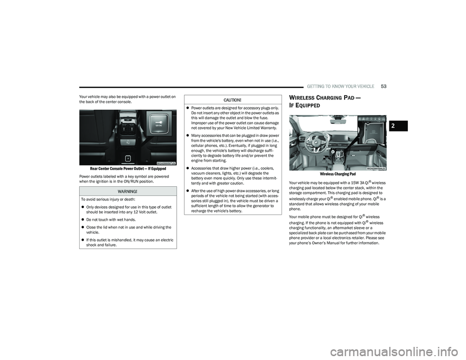
Your vehicle may also be equipped with a power outlet on
the back of the center console.
Rear Center Console Power Outlet — If Equipped
Power outlets labeled with a key symbol are powered
when the ignition is in the ON/RUN position.
WIRELESS CHARGING PAD —
I
F EQUIPPED
Wireless Charging Pad
Your vehicle may be equipped with a 15W 3A Qi® wireless
charging pad located below the center stack, within the
storage compartment. This charging pad is designed to
wirelessly charge your Qi
® enabled mobile phone. Qi® is a
standard that allows wireless charging of your mobile
phone.
Your mobile phone must be designed for Qi
® wireless
charging. If the phone is not equipped with Qi® wireless
charging functionality, an aftermarket sleeve or a
specialized back plate can be purchased from your mobile
phone provider or a local electronics retailer. Please see
your phone’s Owner’s Manual for further information.
WARNING!
To avoid serious injury or death:
Only devices designed for use in this type of outlet
should be inserted into any 12 Volt outlet.
Do not touch with wet hands.
Close the lid when not in use and while driving the
vehicle.
If this outlet is mishandled, it may cause an electric
shock and failure.
CAUTION!
Power outlets are designed for accessory plugs only.
Do not insert any other object in the power outlets as
this will damage the outlet and blow the fuse.
Improper use of the power outlet can cause damage
not covered by your New Vehicle Limited Warranty.
Many accessories that can be plugged in draw power
from the vehicle's battery, even when not in use (i.e.,
cellular phones, etc.). Eventually, if plugged in long
enough, the vehicle's battery will discharge suffi -
ciently to degrade battery life and/or prevent the
engine from starting.
Accessories that draw higher power (i.e., coolers,
vacuum cleaners, lights, etc.) will degrade the
battery even more quickly. Only use these intermit -
tently and with greater caution.
After the use of high power draw accessories, or long
periods of the vehicle not being started (with acces -
sories still plugged in), the vehicle must be driven a
sufficient length of time to allow the generator to
recharge the vehicle's battery.
2
23_GG_OM_EN_USC_t.book Page 53
Page 228 of 288
226SERVICING AND MAINTENANCE
ENGINE COMPARTMENT
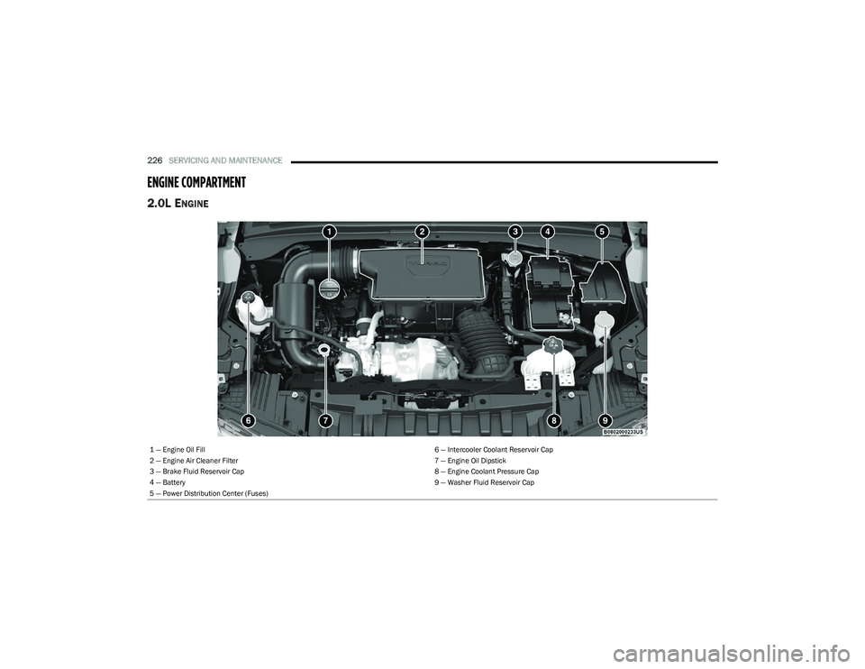
2.0L ENGINE
1 — Engine Oil Fill 6 — Intercooler Coolant Reservoir Cap
2 — Engine Air Cleaner Filter 7 — Engine Oil Dipstick
3 — Brake Fluid Reservoir Cap 8 — Engine Coolant Pressure Cap
4 — Battery 9 — Washer Fluid Reservoir Cap
5 — Power Distribution Center (Fuses)
23_GG_OM_EN_USC_t.book Page 226
Page 239 of 288
SERVICING AND MAINTENANCE237
Fluid And Filter Changes
Under normal operating conditions, the fluid installed at
the factory will provide satisfactory lubrication for the life
of the vehicle.
Routine fluid and filter changes are not required. However,
change the fluid and filter if the fluid becomes
contaminated (with water, etc.), or if the transmission is
disassembled for any reason.
Selection Of Lubricant
It is important to use the proper transmission fluid to
ensure optimum transmission performance and life.
Use only the manufacturer specified transmission fluid
Úpage 269. It is important to maintain the transmission
fluid at the correct level using the recommended fluid.
NOTE:No chemical flushes should be used in any transmission;
only the approved lubricant should be used.
FUSES
General Information
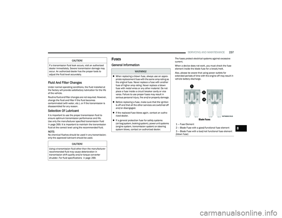
The fuses protect electrical systems against excessive
current.
When a device does not work, you must check the fuse
element inside the blade fuse for a break/melt.
Also, please be aware that using power outlets for
extended periods of time with the engine off may result in
vehicle battery discharge.
Blade Fuses
CAUTION!
If a transmission fluid leak occurs, visit an authorized
dealer immediately. Severe transmission damage may
occur. An authorized dealer has the proper tools to
adjust the fluid level accurately.
CAUTION!
Using a transmission fluid other than the manufacturer
recommended fluid may cause deterioration in
transmission shift quality and/or torque converter
shudder. For fluid specifications
Úpage 269.
WARNING!
When replacing a blown fuse, always use an appro -
priate replacement fuse with the same amp rating as
the original fuse. Never replace a fuse with another
fuse of higher amp rating. Never replace a blown
fuse with metal wires or any other material. Do not
place a fuse inside a circuit breaker cavity or vice
versa. Failure to use proper fuses may result in
serious personal injury, fire and/or property damage.
Before replacing a fuse, make sure that the ignition
is off and that all the other services are switched off
and/or disengaged.
If the replaced fuse blows again, contact an autho -
rized dealer.
If a general protection fuse for safety systems
(air bag system, braking system), power unit systems
(engine system, transmission system) or steering
system blows, contact an authorized dealer.
1 — Fuse Element
2 — Blade Fuse with a good/functional fuse element
3 — Blade Fuse with a bad/not functional fuse element
(blown fuse)
8
23_GG_OM_EN_USC_t.book Page 237
Page 240 of 288
238SERVICING AND MAINTENANCE
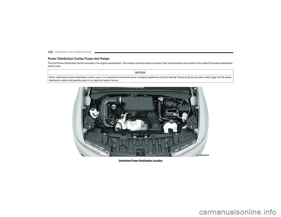
Power Distribution Center/Fuses And Relays
The Front Power Distribution Center is located in the engine compartment. This module contains fuses and relays. Fuse cavity locations are printed on the inside of the power distribution
center cover.
Underhood Power Distribution Location
CAUTION!
When installing the power distribution center cover, it is important to ensure the cover is properly positioned and fully latched. Failure to do so may allow water to get into the power
distribution center and possibly result in an electrical system failure.
23_GG_OM_EN_USC_t.book Page 238
Page 241 of 288
SERVICING AND MAINTENANCE239
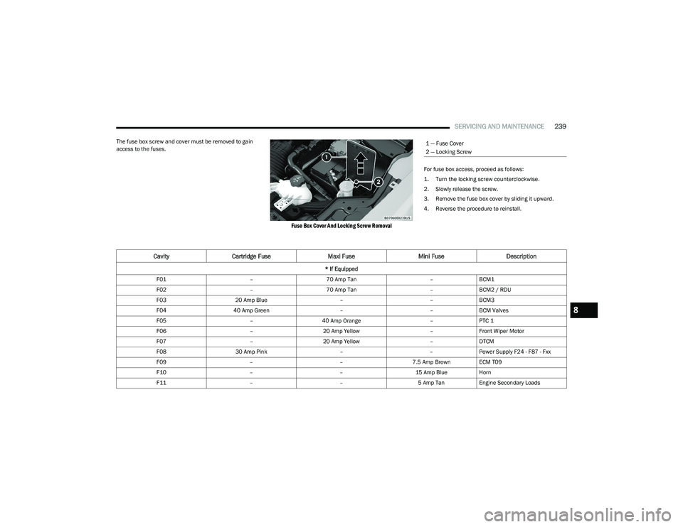
The fuse box screw and cover must be removed to gain
access to the fuses.
Fuse Box Cover And Locking Screw Removal
For fuse box access, proceed as follows:
1. Turn the locking screw counterclockwise.
2. Slowly release the screw.
3. Remove the fuse box cover by sliding it upward.
4. Reverse the procedure to reinstall.
1 — Fuse Cover
2 — Locking Screw
CavityCartridge Fuse Maxi FuseMini FuseDescription
* If Equipped
F01 –70 Amp Tan –BCM1
F02 –70 Amp Tan –BCM2 / RDU
F03 20 Amp Blue ––BCM3
F04 40 Amp Green ––BCM Valves
F05 –40 Amp Orange –PTC 1
F06 –20 Amp Yellow –Front Wiper Motor
F07 –20 Amp Yellow –DTCM
F08 30 Amp Pink ––Power Supply F24 - F87 - Fxx
F09 ––7.5 Amp Brown ECM T09
F10 ––15 Amp BlueHorn
F11 ––5 Amp TanEngine Secondary Loads
8
23_GG_OM_EN_USC_t.book Page 239
Page 242 of 288
240SERVICING AND MAINTENANCE
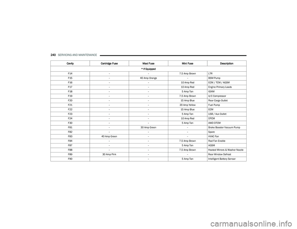
F14 ––7.5 Amp Brown LTR
F15 –40 Amp Orange –BSM Pump
F16 ––10 Amp RedECM / TCM / AGSM
F17 ––10 Amp RedEngine Primary Loads
F18 ––5 Amp TanIGNM
F19 ––7.5 Amp Brown A/C Compressor
F20 ––15 Amp BlueRear Cargo Outlet
F21 ––20 Amp Yellow Fuel Pump
F22 ––15 Amp BlueECM
F23 ––5 Amp TanUSB / Aux Outlet
F24 ––10 Amp RedDTCM
F30 ––5 Amp TanAWD DTCM
F81 –30 Amp Green –Brake Booster Vacuum Pump
F82 –––Spare
F83 40 Amp Green ––HVAC Fan
F84 ––7.5 Amp Brown Rad Fan Enable
F87 ––5 Amp TanAGSM
F88 ––7.5 Amp Brown Heated Mirrors & Washer Nozzle
F89 30 Amp Pink ––Rear Window Defrost
F90 ––5 Amp TanIntelligent Battery Sensor
Cavity Cartridge Fuse Maxi FuseMini FuseDescription
* If Equipped
23_GG_OM_EN_USC_t.book Page 240
Page 243 of 288
SERVICING AND MAINTENANCE241
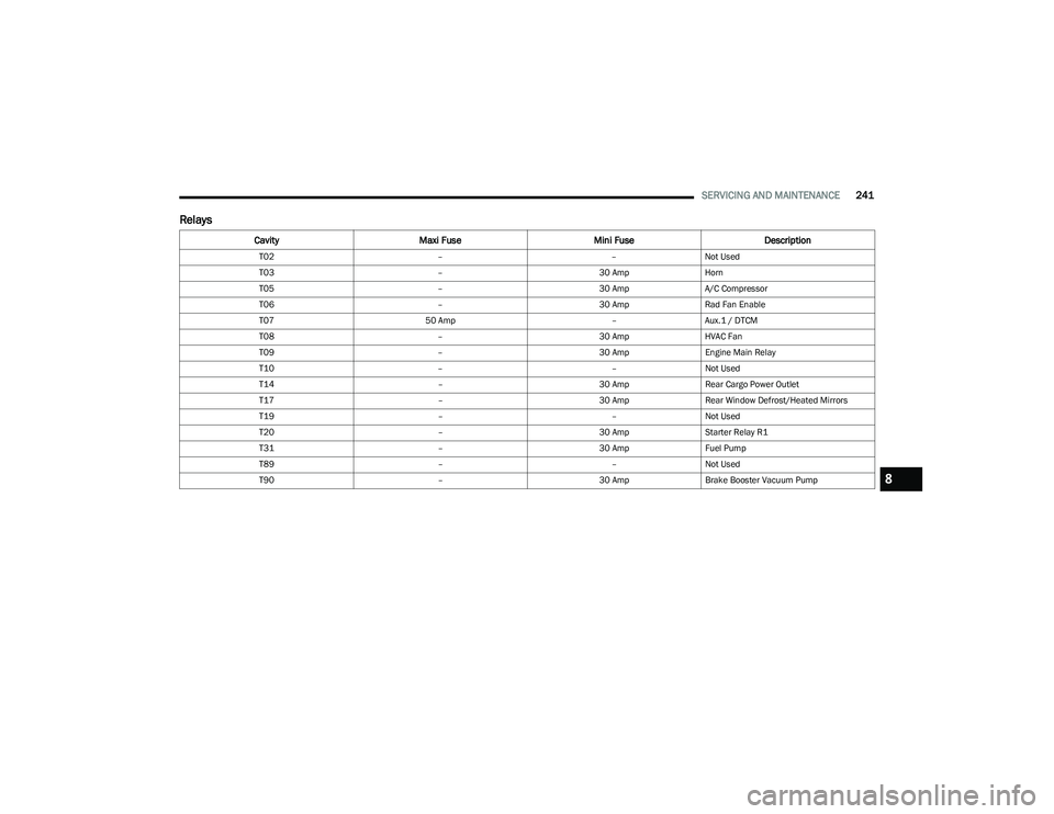
Relays
Cavity Maxi Fuse Mini FuseDescription
T02 ––Not Used
T03 –30 AmpHorn
T05 –30 AmpA/C Compressor
T06 –30 AmpRad Fan Enable
T07 50 Amp –Aux.1 / DTCM
T08 –30 AmpHVAC Fan
T09 –30 AmpEngine Main Relay
T10 ––Not Used
T14 –30 AmpRear Cargo Power Outlet
T17 –30 AmpRear Window Defrost/Heated Mirrors
T19 ––Not Used
T20 –30 AmpStarter Relay R1
T31 –30 AmpFuel Pump
T89 ––Not Used
T90 –30 AmpBrake Booster Vacuum Pump
8
23_GG_OM_EN_USC_t.book Page 241
Page 244 of 288
242SERVICING AND MAINTENANCE
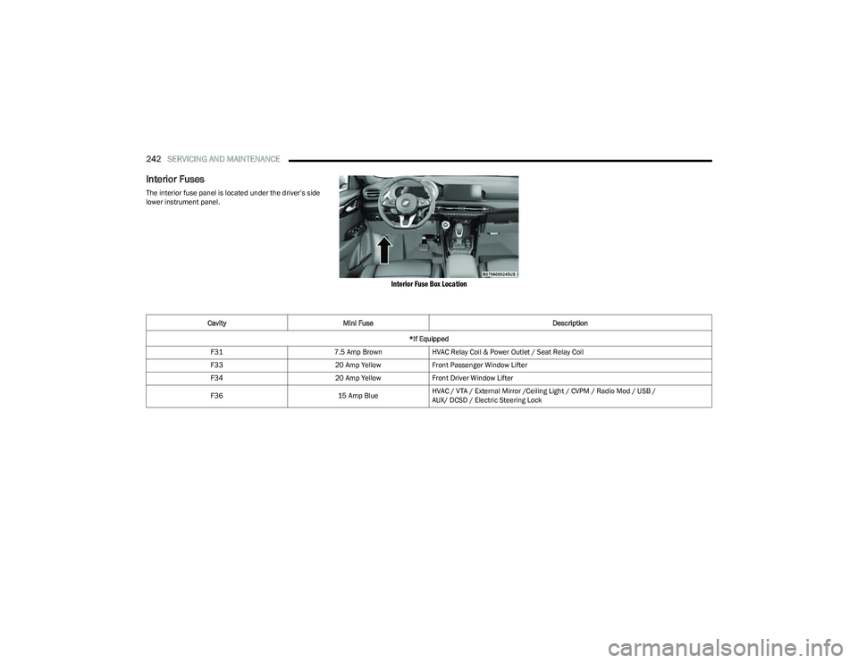
Interior Fuses
The interior fuse panel is located under the driver’s side
lower instrument panel.
Interior Fuse Box Location
Cavity Mini Fuse Description
*If Equipped
F31 7.5 Amp BrownHVAC Relay Coil & Power Outlet / Seat Relay Coil
F33 20 Amp YellowFront Passenger Window Lifter
F34 20 Amp YellowFront Driver Window Lifter
F36 15 Amp BlueHVAC / VTA / External Mirror /Ceiling Light / CVPM / Radio Mod / USB /
AUX/ DCSD / Electric Steering Lock
23_GG_OM_EN_USC_t.book Page 242
Page 245 of 288
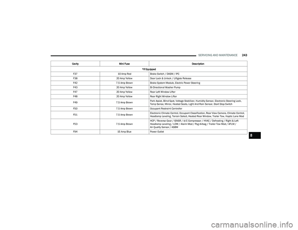
SERVICING AND MAINTENANCE243
F37 10 Amp RedBrake Switch / DASM / IPC
F38 20 Amp YellowDoor Lock & Unlock / Liftgate Release
F42 7.5 Amp BrownBrake System Module, Electric Power Steering
F43 20 Amp YellowBi-Directional Washer Pump
F47 20 Amp YellowRear Left Window Lifter
F48 20 Amp YellowRear Right Window Lifter
F49 7.5 Amp BrownPark Assist, Blind Spot, Voltage Stabilizer, Humidity Sensor, Electronic Steering Lock,
Temp Sense, Mirror, Heated Seats, Light And Rain Sensor, Start Stop Switch
F50 7.5 Amp BrownOccupant Restraint Controller
F51 7.5 Amp BrownElectronic Climate Control, Occupant Classification, Rear View Camera, Climate Control,
Headlamp Leveling, Terrain Select, Heated Rear Window, Trailer Tow, Haptic Lane Mod
F53 7.5 Amp BrownHCP / Reverse Gear / ISNSR / A/C Compressor / HVAC / Defrosting / Right & Left
Headlamp Leveling / LDW / Alarm Mod / Psg Airbag / Trailer Tow Mod / AFLM /
Air Quality Sensor / ASBM
F94 15 Amp BluePower Outlet
Cavity
Mini Fuse Description
*If Equipped
8
23_GG_OM_EN_USC_t.book Page 243