instrument panel DODGE HORNET 2023 Owners Manual
[x] Cancel search | Manufacturer: DODGE, Model Year: 2023, Model line: HORNET, Model: DODGE HORNET 2023Pages: 288, PDF Size: 14.2 MB
Page 3 of 288
TABLE OF CONTENTS
1
2
3
4
5
6
7
8
9
10
11
1 INTRODUCTION .............................................................................................................................. 7
2 GETTING TO KNOW YOUR VEHICLE ..................................................................................13
3 GETTING TO KNOW YOUR INSTRUMENT PANEL ....................................................... 65
4 STARTING AND OPERATING ................................................................................................ 80 5 MULTIMEDIA ............................................................................................................................... 129
6 SAFETY ......................................................................................................................................... 154 7 IN CASE OF EMERGENCY ....................................................................................................203
8 SERVICING AND MAINTENANCE ...................................................................................... 223
9 TECHNICAL SPECIFICATIONS ............................................................................................ 265
10 CUSTOMER ASSISTANCE ..................................................................................................... 270 11 INDEX ............................................................................................................................................. 277
23_GG_OM_EN_USC_t.book Page 1
Page 5 of 288
3
EXTERIOR LIGHTS ...............................................................40Multifunction Lever .................................................... 40
Headlight Switch ......................................................... 40
Daytime Running Lights (DRLs) —
If Equipped .................................................................. 40
High/Low Beam Switch ............................................. 40
Automatic High Beam Headlamp Control —
If Equipped ................................................................. 41
Flash-To-Pass .............................................................. 41
Automatic Headlights — If Equipped ......................... 41
Headlights On Automatically With Wipers —
If Equipped .................................................................. 41
Headlight Delay ........................................................... 41
Lights-On Reminder .................................................... 41
Cornering Lights — If Equipped .................................. 41
Turn Signals ................................................................ 42
Lane Change Assist ................................................... 42
Battery Saver Feature................................................. 42
INTERIOR LIGHTS................................................................42 Interior Courtesy Lights............................................... 42
WINDSHIELD WIPERS AND WASHERS ........................... 44 Windshield Wiper Operation....................................... 44
Rain Sensing Wipers — If Equipped .......................... 45
Rear Window Wiper/Washer ..................................... 46
CLIMATE CONTROLS ..........................................................46 Automatic Climate Control Descriptions And
Functions ..................................................................... 46
Automatic Temperature
Control (ATC) ............................................................... 49
Climate Voice Commands .......................................... 49
Operating Tips ............................................................ 49 INTERIOR STORAGE AND EQUIPMENT ............................ 50
Storage ......................................................................... 50
USB Control .................................................................. 51
Power Outlets — If Equipped ....................................... 52
Wireless Charging Pad —
If Equipped ................................................................... 53
WINDOWS .......................................................................... 55 Power Window Controls............................................... 55
Automatic Window Features ......................................55
Power Window System Initialization........................... 55
Window Lockout Switch ..............................................56
Wind Buffeting ............................................................ 56
POWER SUNROOF — IF EQUIPPED ................................. 56 Opening And Closing The Sunroof ..............................57
Opening And Closing The Power Sunshade ............... 57
Pinch Protect Feature.................................................. 57
Re-Initialization Procedure .......................................... 58
Sunroof Maintenance.................................................. 58
HOOD ................................................................................... 58 Opening The Hood .......................................................58
Closing The Hood ......................................................... 59
LIFTGATE .............................................................................. 59 Unlock/Open The Liftgate ........................................... 59
Lock/Close The Liftgate ..............................................60
Power Liftgate — If Equipped ......................................60
Adjustable Power Liftgate Height ............................... 61
Hands-Free Liftgate — If Equipped ............................ 62
Cargo Area Features.................................................... 63GETTING TO KNOW YOUR
INSTRUMENT PANEL
PREMIUM INSTRUMENT CLUSTER................................... 65 Instrument Cluster Descriptions
b
.......................... 66
INSTRUMENT CLUSTER DISPLAY ..................................... 66 Instrument Cluster Display Location And
Controls........................................................................ 66
Oil Change Reset
b
.................................................. 68
Oil Change Indicator System ...................................... 68
Gear Shift Indicator (GSI) —
If Equipped................................................................... 68
Instrument Cluster Display Menu Items ................... 68
Battery Saver On/Battery Saver Mode Message —
Electrical Load Reduction Actions — If Equipped ...... 70
WARNING LIGHTS AND MESSAGES ................................ 71 Red Warning Lights ..................................................... 71
Yellow Warning Lights ................................................. 73
Yellow Indicator Lights ................................................ 77
Green Indicator Lights................................................. 77
White Indicator Lights ................................................. 78
Blue Indicator Lights ................................................... 78
ONBOARD DIAGNOSTIC SYSTEM — OBD II .................... 78 Onboard Diagnostic System (OBD II)
Cybersecurity ............................................................... 79
EMISSIONS INSPECTION AND MAINTENANCE
PROGRAMS ......................................................................... 79
23_GG_OM_EN_USC_t.book Page 3
Page 42 of 288
40GETTING TO KNOW YOUR VEHICLE
EXTERIOR LIGHTS
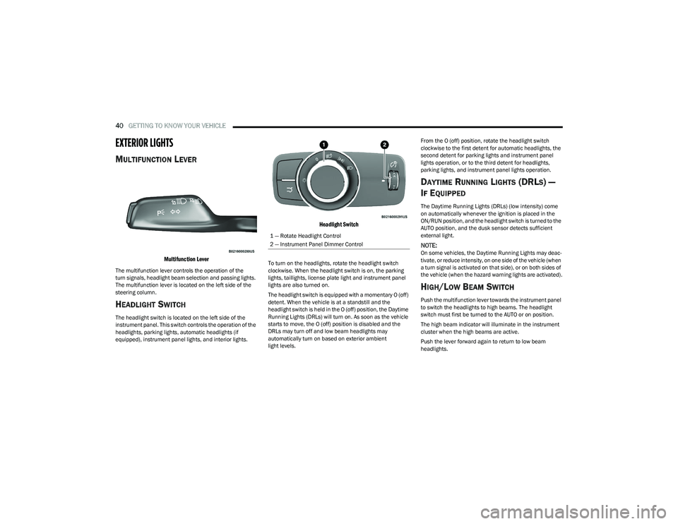
MULTIFUNCTION LEVER
Multifunction Lever
The multifunction lever controls the operation of the
turn signals, headlight beam selection and passing lights.
The multifunction lever is located on the left side of the
steering column.
HEADLIGHT SWITCH
The headlight switch is located on the left side of the
instrument panel. This switch controls the operation of the
headlights, parking lights, automatic headlights (if
equipped), instrument panel lights, and interior lights.
Headlight Switch
To turn on the headlights, rotate the headlight switch
clockwise. When the headlight switch is on, the parking
lights, taillights, license plate light and instrument panel
lights are also turned on.
The headlight switch is equipped with a momentary O (off)
detent. When the vehicle is at a standstill and the
headlight switch is held in the O (off) position, the Daytime
Running Lights (DRLs) will turn on. As soon as the vehicle
starts to move, the O (off) position is disabled and the
DRLs may turn off and low beam headlights may
automatically turn on based on exterior ambient
light levels. From the O (off) position, rotate the headlight switch
clockwise to the first detent for automatic headlights, the
second detent for parking lights and instrument panel
lights operation, or to the third detent for headlights,
parking lights, and instrument panel lights operation.
DAYTIME RUNNING LIGHTS (DRLS) —
I
F EQUIPPED
The Daytime Running Lights (DRLs) (low intensity) come
on automatically whenever the ignition is placed in the
ON/RUN position, and the headlight switch is turned to the
AUTO position, and the dusk sensor detects sufficient
external light.
NOTE:On some vehicles, the Daytime Running Lights may deac -
tivate, or reduce intensity, on one side of the vehicle (when
a turn signal is activated on that side), or on both sides of
the vehicle (when the hazard warning lights are activated).
HIGH/LOW BEAM SWITCH
Push the multifunction lever towards the instrument panel
to switch the headlights to high beams. The headlight
switch must first be turned to the AUTO or on position.
The high beam indicator will illuminate in the instrument
cluster when the high beams are active.
Push the lever forward again to return to low beam
headlights.
1 — Rotate Headlight Control
2 — Instrument Panel Dimmer Control
23_GG_OM_EN_USC_t.book Page 40
Page 43 of 288
GETTING TO KNOW YOUR VEHICLE41
AUTOMATIC HIGH BEAM HEADLAMP
C
ONTROL — IF EQUIPPED
The Automatic High Beam Headlamp Control system
provides increased forward lighting at night by automating
high beam control through the use of a digital camera
mounted on the windshield. This camera detects vehicle
specific light and automatically switches from high beams
to low beams until the approaching vehicle is out of view.
NOTE:
The Automatic High Beam Headlamp Control can be
turned on or off through Uconnect Settings.
This function can only be activated with the headlight
switch in the AUTO position.
Broken, muddy, or obstructed headlights and taillights
of vehicles in the field of view will cause headlights to
remain on longer (closer to the vehicle). Also, dirt, film,
and other obstructions on the windshield or camera
lens will cause the system to function improperly.
FLASH-TO-PASS
You can signal another vehicle with your headlights by
lightly pulling the multifunction lever toward you. This will
cause the high beam headlights to turn on, and remain on,
until the lever is released.
AUTOMATIC HEADLIGHTS — IF EQUIPPED
This system automatically turns the headlights
on or off according to ambient light levels. To
turn the system on, rotate the headlight switch
clockwise to the AUTO position.
When the system is on, the headlight time delay feature is
also on. This means the headlights will stay on for up to
90 seconds after you place the ignition into the OFF
position. To turn the automatic system off, move the
headlight switch out of the AUTO position.
NOTE:The engine must be running before the headlights will
come on in the automatic mode.
HEADLIGHTS ON AUTOMATICALLY WITH
W
IPERS — IF EQUIPPED
If your vehicle is equipped with Automatic Headlights, it
also has this customer-programmable feature. When your
headlights are in the automatic mode and the engine is
running, they will automatically turn on when the wiper
system is on. This feature is programmable through the
Uconnect system.
NOTE:When your headlights come on during the daytime, the
vehicle will monitor outside brightness and decide if the
instrument panel needs to be dimmed.
HEADLIGHT DELAY
To aid in your exit, your vehicle is equipped with a
headlight delay that will leave the headlights on for
approximately 90 seconds. This delay is initiated when the
ignition is placed in the OFF position while the headlight
switch is on, and then the headlight switch is cycled off.
Headlight delay can be canceled by either turning the
headlight switch on then off, or by placing the ignition in
the ON/RUN position.
NOTE:The headlight delay time is programmable through
Uconnect Settings Úpage 130.
LIGHTS-ON REMINDER
If the headlights or parking lights are on after the ignition
is in the OFF position, a chime will sound to alert the driver
when the driver's door is opened.
CORNERING LIGHTS — IF EQUIPPED
The cornering lights are a feature to improve visibility at
night while turning the vehicle. When activated, a light
incorporated in the headlight assembly will illuminate on
the side of the vehicle the steering wheel is rotated, or that
the turn signal indicator is on. It can be activated through
the Uconnect system
Úpage 130.
2
23_GG_OM_EN_USC_t.book Page 41
Page 45 of 288
GETTING TO KNOW YOUR VEHICLE43
Overhead Light Timing
On certain models, to assist getting in and out of the
vehicle at night or in poorly-lit areas, two timed modes
have been provided.
Timing While Getting Into The Vehicle
The overhead lights turn on according to the following
modes:
Will illuminate for approximately three minutes when
the doors are unlocked.
Will illuminate for approximately three minutes when
one of the doors is opened.
Will illuminate for approximately 27 seconds when
each individual door is closed and switch off simultane -
ously when the doors are locked.
Timing is interrupted when the ignition is placed in the
ON/RUN position.
Three Modes Are Available For Turning Off Overhead
Lighting:
When all doors are closed after entering the vehicle,
the three-minute timer will stop and a seconds timer
will start for the interior lights. This timing will stop
when the ignition is placed in the ON/RUN position.
When doors are locked (either with key fob or with the
emergency key inserted in driver side door), the over -
head light turns off.
The interior lights will turn off after 15 minutes to
preserve the battery. Timing While Getting Out Of The Vehicle
After placing the ignition in the OFF position, the overhead
lights will turn on as follows:
For a few seconds after the engine stops.
For approximately three minutes when one of the doors
is opened.
For several seconds when the last door is closed.
The timing stops automatically when the doors are locked.
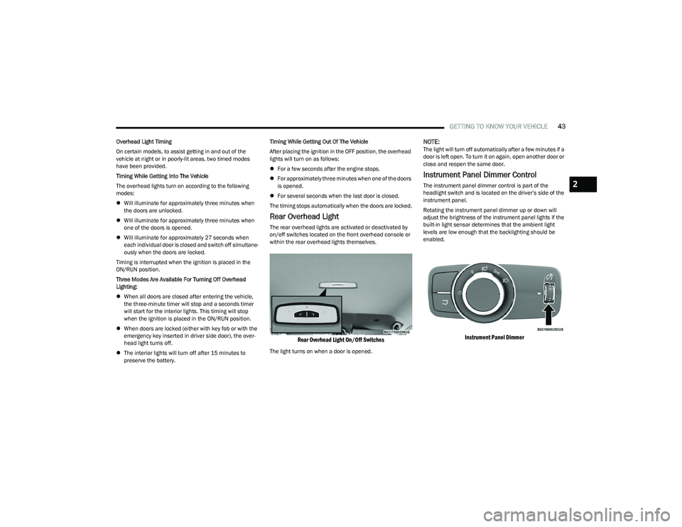
Rear Overhead Light
The rear overhead lights are activated or deactivated by
on/off switches located on the front overhead console or
within the rear overhead lights themselves.
Rear Overhead Light On/Off Switches
The light turns on when a door is opened.
NOTE:The light will turn off automatically after a few minutes if a
door is left open. To turn it on again, open another door or
close and reopen the same door.
Instrument Panel Dimmer Control
The instrument panel dimmer control is part of the
headlight switch and is located on the driver’s side of the
instrument panel.
Rotating the instrument panel dimmer up or down will
adjust the brightness of the instrument panel lights if the
built-in light sensor determines that the ambient light
levels are low enough that the backlighting should be
enabled.
Instrument Panel Dimmer
2
23_GG_OM_EN_USC_t.book Page 43
Page 48 of 288
46GETTING TO KNOW YOUR VEHICLE
The rain sensor is able to recognize and automatically
adjust itself when the following conditions occur:
Presence of dirt on the controlled surface
(e.g. salt, dirt, etc.).
Presence of streaks of water caused by the worn
window wiper blades.
Difference between day and night.
REAR WINDOW WIPER/WASHER
Shifting the vehicle into REVERSE with the windshield wiper
operating activates a single cycle of the rear window wiper.
Push the windshield wiper lever downward (with the
vehicle in REVERSE) to activate/deactivate continuous
rear wiper operation.
Push the windshield wiper lever downward (without the
vehicle in REVERSE) to activate/deactivate intermittent
rear wiper operation.
Push the windshield wiper lever towards the instrument
panel to activate the rear window washer (a brief push
activates one washing cycle, while keeping the stalk
pushed washes continuously until the stalk is released).
NOTE:Make sure the rear wiper is turned off when cleaning the
windshield glass.
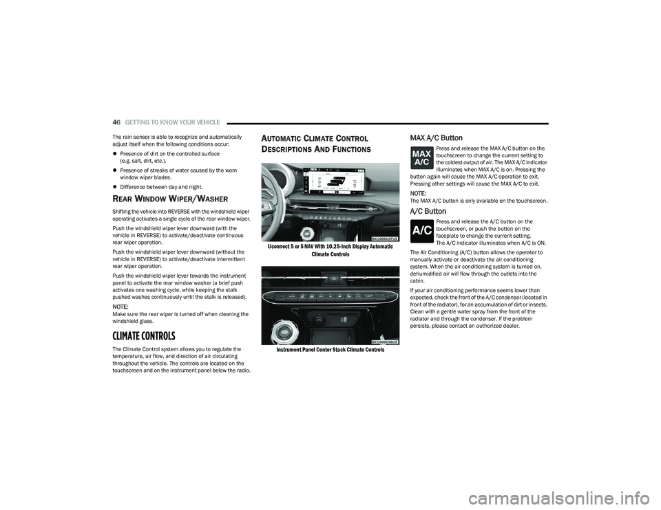
CLIMATE CONTROLS
The Climate Control system allows you to regulate the
temperature, air flow, and direction of air circulating
throughout the vehicle. The controls are located on the
touchscreen and on the instrument panel below the radio.
AUTOMATIC CLIMATE CONTROL
D
ESCRIPTIONS AND FUNCTIONS
Uconnect 5 or 5 NAV With 10.25-Inch Display Automatic
Climate Controls
Instrument Panel Center Stack Climate Controls
MAX A/C Button
Press and release the MAX A/C button on the
touchscreen to change the current setting to
the coldest output of air. The MAX A/C indicator
illuminates when MAX A/C is on. Pressing the
button again will cause the MAX A/C operation to exit.
Pressing other settings will cause the MAX A/C to exit.
NOTE:The MAX A/C button is only available on the touchscreen.
A/C Button
Press and release the A/C button on the
touchscreen, or push the button on the
faceplate to change the current setting.
The A/C indicator illuminates when A/C is ON.
The Air Conditioning (A/C) button allows the operator to
manually activate or deactivate the air conditioning
system. When the air conditioning system is turned on,
dehumidified air will flow through the outlets into the
cabin.
If your air conditioning performance seems lower than
expected, check the front of the A/C condenser (located in
front of the radiator), for an accumulation of dirt or insects.
Clean with a gentle water spray from the front of the
radiator and through the condenser. If the problem
persists, please contact an authorized dealer.
23_GG_OM_EN_USC_t.book Page 46
Page 50 of 288
48GETTING TO KNOW YOUR VEHICLE
Driver And Passenger Temperature
Control Buttons
These buttons provide the driver and passenger with
independent temperature control.
SYNC Button
Press the SYNC button on the touchscreen to
toggle the Sync feature on/off. The SYNC
indicator is illuminated when SYNC is on. SYNC
is used to synchronize the passenger
temperature setting with the driver temperature setting.
Changing the passenger temperature setting while in
SYNC will automatically exit this feature.
NOTE:The SYNC button is only available on the touchscreen.
Blower Control
Blower Control is used to regulate the amount of
air forced through the Climate Control system.
There are seven blower speeds available.
Adjusting the blower will cause automatic mode
to switch to manual operation. The speeds can be selected
using either the blower control buttons on the faceplate or
the buttons on the touchscreen.
Faceplate
Press the small blower icon button to decrease the blower
speed, or press the large blower icon button to increase
the blower speed.
Touchscreen
Blower speed can also be selected by pressing a number
on the blower bar area.
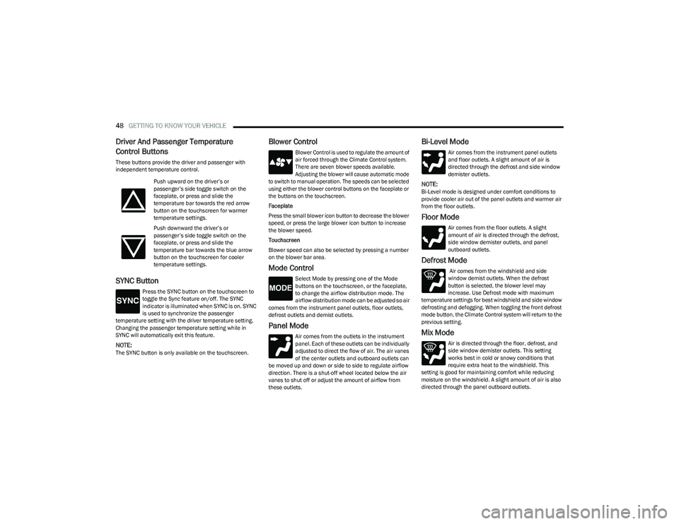
Mode Control
Select Mode by pressing one of the Mode
buttons on the touchscreen, or the faceplate,
to change the airflow distribution mode. The
airflow distribution mode can be adjusted so air
comes from the instrument panel outlets, floor outlets,
defrost outlets and demist outlets.
Panel Mode
Air comes from the outlets in the instrument
panel. Each of these outlets can be individually
adjusted to direct the flow of air. The air vanes
of the center outlets and outboard outlets can
be moved up and down or side to side to regulate airflow
direction. There is a shut-off wheel located below the air
vanes to shut off or adjust the amount of airflow from
these outlets.
Bi-Level Mode
Air comes from the instrument panel outlets
and floor outlets. A slight amount of air is
directed through the defrost and side window
demister outlets.
NOTE:Bi-Level mode is designed under comfort conditions to
provide cooler air out of the panel outlets and warmer air
from the floor outlets.
Floor Mode
Air comes from the floor outlets. A slight
amount of air is directed through the defrost,
side window demister outlets, and panel
outboard outlets.
Defrost Mode
Air comes from the windshield and side
window demist outlets. When the defrost
button is selected, the blower level may
increase. Use Defrost mode with maximum
temperature settings for best windshield and side window
defrosting and defogging. When toggling the front defrost
mode button, the Climate Control system will return to the
previous setting.
Mix Mode
Air is directed through the floor, defrost, and
side window demister outlets. This setting
works best in cold or snowy conditions that
require extra heat to the windshield. This
setting is good for maintaining comfort while reducing
moisture on the windshield. A slight amount of air is also
directed through the panel outboard outlets.
Push upward on the driver’s or
passenger’s side toggle switch on the
faceplate, or press and slide the
temperature bar towards the red arrow
button on the touchscreen for warmer
temperature settings.
Push downward the driver’s or
passenger’s side toggle switch on the
faceplate, or press and slide the
temperature bar towards the blue arrow
button on the touchscreen for cooler
temperature settings.
23_GG_OM_EN_USC_t.book Page 48
Page 52 of 288
50GETTING TO KNOW YOUR VEHICLE
Winter Operation
To ensure the best possible heater and defroster
performance, make sure the engine cooling system is
functioning properly and the proper amount, type, and
concentration of coolant is used. Use of the Air
Recirculation mode during Winter months is not
recommended, because it may cause window fogging.
Vacation/Storage
For information on maintaining the Climate Control system
when the vehicle is being stored for an extended period of
time, see
Úpage 261.
Window Fogging
Vehicle windows tend to fog on the inside in mild, rainy,
and/or humid weather. To clear the windows, select
Defrost or Mix mode and increase the front blower speed.
Do not use the Recirculation mode without A/C for long
periods, as fogging may occur.
Outside Air Intake
Make sure the air intake, located directly in front of the
windshield, is free of obstructions, such as leaves. Leaves
collected in the air intake may reduce airflow, and if they
enter the air distribution box, they could plug the water
drains. In Winter months, make sure the air intake is clear
of ice, slush, and snow.
Cabin Air Filter
The Climate Control system filters out dust and pollen
from the air. Contact an authorized dealer to service your
cabin air filter, and to have it replaced when needed.
Operating Tips ChartINTERIOR STORAGE AND EQUIPMENT
STORAGE
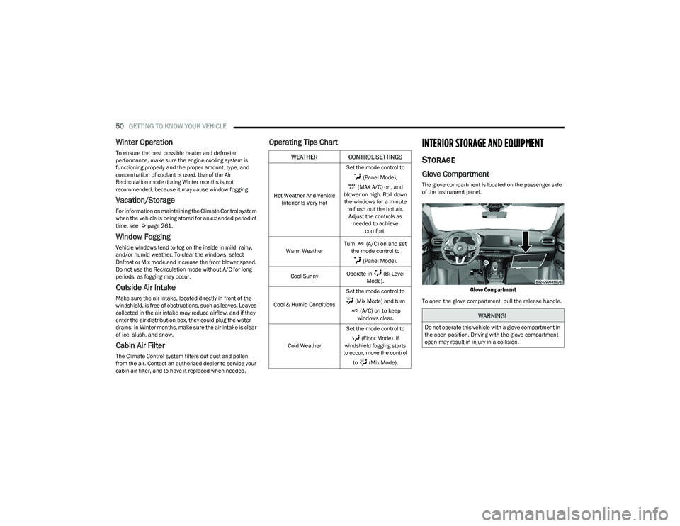
Glove Compartment
The glove compartment is located on the passenger side
of the instrument panel.
Glove Compartment
To open the glove compartment, pull the release handle.
WEATHER CONTROL SETTINGS
Hot Weather And Vehicle
Interior Is Very Hot Set the mode control to
(Panel Mode),
(MAX A/C) on, and
blower on high. Roll down the windows for a minute to flush out the hot air. Adjust the controls as needed to achieve comfort.
Warm Weather Turn (A/C) on and set
the mode control to
(Panel Mode).
Cool Sunny Operate in (Bi-Level
Mode).
Cool & Humid Conditions Set the mode control to
(Mix Mode) and turn (A/C) on to keep
windows clear.
Cold Weather Set the mode control to
(Floor Mode). If
windshield fogging starts
to occur, move the control
to (Mix Mode).
WARNING!
Do not operate this vehicle with a glove compartment in
the open position. Driving with the glove compartment
open may result in injury in a collision.
23_GG_OM_EN_USC_t.book Page 50
Page 54 of 288
52GETTING TO KNOW YOUR VEHICLE
By using a USB cable to connect an external device:
The device can be played on the vehicle’s sound
system, providing the artist, track title, and album infor -
mation on the radio display.
NOTE:Depending on track configuration, track information may
not be present on the radio display.
The device can be controlled using the radio buttons to
play, and browse the contents of the device.
The audio device battery charges when plugged into
the USB port.
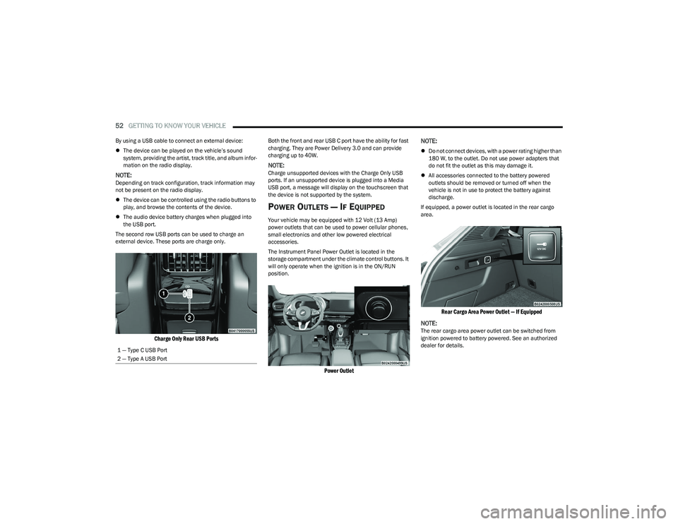
The second row USB ports can be used to charge an
external device. These ports are charge only.
Charge Only Rear USB Ports
Both the front and rear USB C port have the ability for fast
charging. They are Power Delivery 3.0 and can provide
charging up to 40W.
NOTE:Charge unsupported devices with the Charge Only USB
ports. If an unsupported device is plugged into a Media
USB port, a message will display on the touchscreen that
the device is not supported by the system.
POWER OUTLETS — IF EQUIPPED
Your vehicle may be equipped with 12 Volt (13 Amp)
power outlets that can be used to power cellular phones,
small electronics and other low powered electrical
accessories.
The Instrument Panel Power Outlet is located in the
storage compartment under the climate control buttons. It
will only operate when the ignition is in the ON/RUN
position.
Power Outlet
NOTE:
Do not connect devices, with a power rating higher than
180 W, to the outlet. Do not use power adapters that
do not fit the outlet as this may damage it.
All accessories connected to the battery powered
outlets should be removed or turned off when the
vehicle is not in use to protect the battery against
discharge.
If equipped, a power outlet is located in the rear cargo
area.
Rear Cargo Area Power Outlet — If Equipped
NOTE:
The rear cargo area power outlet can be switched from
ignition powered to battery powered. See an authorized
dealer for details.
1 — Type C USB Port
2 — Type A USB Port
23_GG_OM_EN_USC_t.book Page 52
Page 60 of 288
58GETTING TO KNOW YOUR VEHICLE
RE-INITIALIZATION PROCEDURE
Automatic operation of the sunroof must be re-initialized
in case of faulty sunroof operation. It may also be
necessary to re-initialize the sunroof after the vehicle’s
battery has been disconnected and then reconnected.
NOTE:The anti-pinch safety device is deactivated during the
re-initialization procedure.
Proceed as follows:
1. Place the ignition in the ON/RUN position.
2. Make sure the sunroof glass and the power sunshade
are fully closed. Release the sunroof close switch,
then push and hold it again within five seconds.
Continue to hold the switch while the sunshade fully
opens, the sunroof glass fully opens, followed by the
glass fully closing then the sunshade fully closing.
3. Release the switch once all of the operations stop. Re-initialization of the sunroof motor is now
complete.
NOTE:If the switch is released prior to full completion of the oper -
ations described, the entire re-initialization procedure
must be repeated from step 1.
4. Confirm express operations for the sunroof glass and sunshade are functional for opening and closing
operations.
SUNROOF MAINTENANCE
Use only a non-abrasive cleaner and a soft cloth to clean
the glass panel. Periodically check for and clear out any
debris that may have collected in the tracks.
HOOD
OPENING THE HOOD
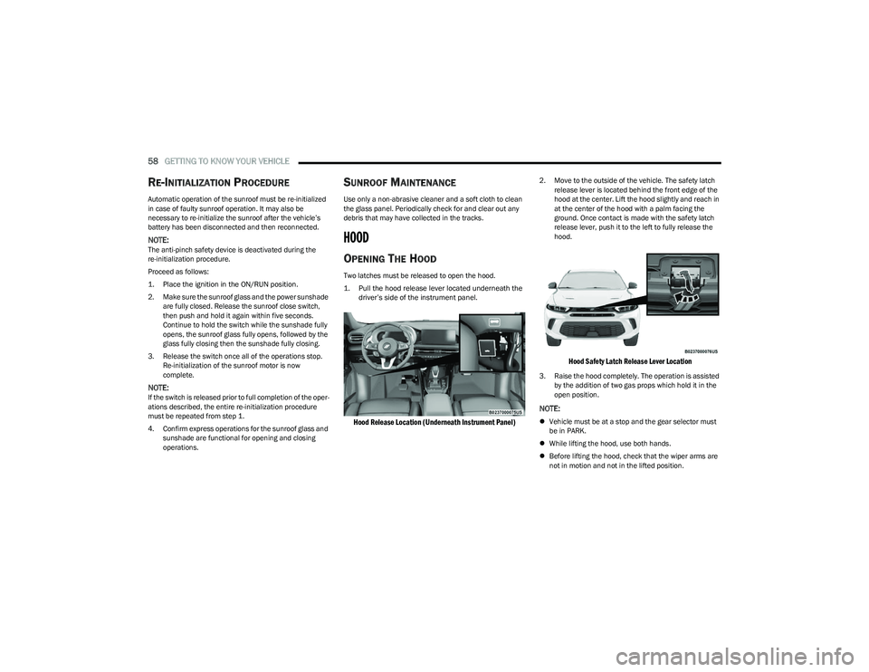
Two latches must be released to open the hood.
1. Pull the hood release lever located underneath the driver’s side of the instrument panel.
Hood Release Location (Underneath Instrument Panel)
2. Move to the outside of the vehicle. The safety latch release lever is located behind the front edge of the
hood at the center. Lift the hood slightly and reach in
at the center of the hood with a palm facing the
ground. Once contact is made with the safety latch
release lever, push it to the left to fully release the
hood.
Hood Safety Latch Release Lever Location
3. Raise the hood completely. The operation is assisted by the addition of two gas props which hold it in the
open position.
NOTE:
Vehicle must be at a stop and the gear selector must
be in PARK.
While lifting the hood, use both hands.
Before lifting the hood, check that the wiper arms are
not in motion and not in the lifted position.
23_GG_OM_EN_USC_t.book Page 58