lane assist DODGE HORNET 2023 Owners Manual
[x] Cancel search | Manufacturer: DODGE, Model Year: 2023, Model line: HORNET, Model: DODGE HORNET 2023Pages: 288, PDF Size: 14.2 MB
Page 5 of 288
3
EXTERIOR LIGHTS ...............................................................40Multifunction Lever .................................................... 40
Headlight Switch ......................................................... 40
Daytime Running Lights (DRLs) —
If Equipped .................................................................. 40
High/Low Beam Switch ............................................. 40
Automatic High Beam Headlamp Control —
If Equipped ................................................................. 41
Flash-To-Pass .............................................................. 41
Automatic Headlights — If Equipped ......................... 41
Headlights On Automatically With Wipers —
If Equipped .................................................................. 41
Headlight Delay ........................................................... 41
Lights-On Reminder .................................................... 41
Cornering Lights — If Equipped .................................. 41
Turn Signals ................................................................ 42
Lane Change Assist ................................................... 42
Battery Saver Feature................................................. 42
INTERIOR LIGHTS................................................................42 Interior Courtesy Lights............................................... 42
WINDSHIELD WIPERS AND WASHERS ........................... 44 Windshield Wiper Operation....................................... 44
Rain Sensing Wipers — If Equipped .......................... 45
Rear Window Wiper/Washer ..................................... 46
CLIMATE CONTROLS ..........................................................46 Automatic Climate Control Descriptions And
Functions ..................................................................... 46
Automatic Temperature
Control (ATC) ............................................................... 49
Climate Voice Commands .......................................... 49
Operating Tips ............................................................ 49 INTERIOR STORAGE AND EQUIPMENT ............................ 50
Storage ......................................................................... 50
USB Control .................................................................. 51
Power Outlets — If Equipped ....................................... 52
Wireless Charging Pad —
If Equipped ................................................................... 53
WINDOWS .......................................................................... 55 Power Window Controls............................................... 55
Automatic Window Features ......................................55
Power Window System Initialization........................... 55
Window Lockout Switch ..............................................56
Wind Buffeting ............................................................ 56
POWER SUNROOF — IF EQUIPPED ................................. 56 Opening And Closing The Sunroof ..............................57
Opening And Closing The Power Sunshade ............... 57
Pinch Protect Feature.................................................. 57
Re-Initialization Procedure .......................................... 58
Sunroof Maintenance.................................................. 58
HOOD ................................................................................... 58 Opening The Hood .......................................................58
Closing The Hood ......................................................... 59
LIFTGATE .............................................................................. 59 Unlock/Open The Liftgate ........................................... 59
Lock/Close The Liftgate ..............................................60
Power Liftgate — If Equipped ......................................60
Adjustable Power Liftgate Height ............................... 61
Hands-Free Liftgate — If Equipped ............................ 62
Cargo Area Features.................................................... 63GETTING TO KNOW YOUR
INSTRUMENT PANEL
PREMIUM INSTRUMENT CLUSTER................................... 65 Instrument Cluster Descriptions
b
.......................... 66
INSTRUMENT CLUSTER DISPLAY ..................................... 66 Instrument Cluster Display Location And
Controls........................................................................ 66
Oil Change Reset
b
.................................................. 68
Oil Change Indicator System ...................................... 68
Gear Shift Indicator (GSI) —
If Equipped................................................................... 68
Instrument Cluster Display Menu Items ................... 68
Battery Saver On/Battery Saver Mode Message —
Electrical Load Reduction Actions — If Equipped ...... 70
WARNING LIGHTS AND MESSAGES ................................ 71 Red Warning Lights ..................................................... 71
Yellow Warning Lights ................................................. 73
Yellow Indicator Lights ................................................ 77
Green Indicator Lights................................................. 77
White Indicator Lights ................................................. 78
Blue Indicator Lights ................................................... 78
ONBOARD DIAGNOSTIC SYSTEM — OBD II .................... 78 Onboard Diagnostic System (OBD II)
Cybersecurity ............................................................... 79
EMISSIONS INSPECTION AND MAINTENANCE
PROGRAMS ......................................................................... 79
23_GG_OM_EN_USC_t.book Page 3
Page 6 of 288
4
STARTING AND OPERATING
STARTING THE ENGINE ......................................................80
Normal Starting ........................................................... 80
Cold Weather Operation
(Below –22°F Or −30°C) .......................................... 81
Extended Park Starting............................................... 81
After Starting — Warming Up The Engine .................. 81
If Engine Fails To Start ............................................... 81
Stopping The Engine ................................................... 82
ENGINE BREAK-IN RECOMMENDATIONS .......................82
PARK BRAKE ....................................................................... 82 Electric Park Brake (EPB) .......................................... 82
AUTOMATIC TRANSMISSION .............................................85 Ignition Park Interlock................................................. 86
Brake/Transmission Shift Interlock (BTSI)
System ......................................................................... 86
9-Speed Automatic Transmission ............................. 86
ALL-WHEEL DRIVE (AWD) ..................................................88
SPORT MODE — IF EQUIPPED ...........................................88
POWER STEERING ..............................................................88
STOP/START SYSTEM — IF EQUIPPED.............................89 Autostop Mode ............................................................ 89
Possible Reasons The Engine Does Not Autostop.... 89
To Start The Engine While In Autostop Mode............ 90
To Manually Turn Off The Stop/Start System ........... 90
To Manually Turn On The Stop/Start System............ 90
System Malfunction .................................................... 90 ACTIVE SPEED LIMITER — IF EQUIPPED .......................... 90
Activation...................................................................... 91
Exceeding The Set Speed ........................................... 91
Deactivation ................................................................. 91
INTELLIGENT SPEED ASSIST (ISA) —
IF EQUIPPED ........................................................................ 91 Activation...................................................................... 92
Sign Capture Modes .................................................... 92
Exceeding The Set Speed ........................................... 92
Deactivation ................................................................. 92
CRUISE CONTROL SYSTEMS ............................................. 92 Adaptive Cruise Control (ACC)..................................... 92
TRAFFIC SIGN RECOGNITION —
IF EQUIPPED ........................................................................ 99 Activation/Deactivation ............................................... 99
Traffic Sign Recognition Modes .................................. 99
Indications On The Display....................................... 100
INTELLIGENT ADAPTIVE CRUISE CONTROL —
IF EQUIPPED ..................................................................... 100 Activation/Deactivation ............................................ 100
ACTIVE DRIVING ASSIST SYSTEM —
IF EQUIPPED ..................................................................... 101 Operation................................................................... 101
Turning Active Driving Assist On Or Off ................... 102
Indications On The Display....................................... 103
Minimum Risk Maneuver ......................................... 104
System Status ........................................................... 104
System Operation/Limitations................................. 104 PARKSENSE FRONT/REAR PARK ASSIST SYSTEM —
IF EQUIPPED ....................................................................105
ParkSense Sensors ................................................... 105
ParkSense Warning Display...................................... 105ParkSense Display .................................................... 105
Enabling And Disabling ParkSense .......................... 106
Service The ParkSense Park Assist System ............ 106
Cleaning The ParkSense System ............................. 106
ParkSense System Usage Precautions .................... 106
Side Distance Warning (SDW) System..................... 107
PARKSENSE ACTIVE PARK ASSIST SYSTEM —
IF EQUIPPED......................................................................108 Enabling And Disabling The ParkSense Active
Park Assist System .................................................... 109
Parallel/Perpendicular Parking Space Assistance
Operation ................................................................... 110Exiting The Parking Space ........................................ 112
LANESENSE — IF EQUIPPED .......................................... 113 LaneSense Operation ............................................... 113Turning LaneSense On Or Off ................................... 114
LaneSense Warning Message .................................. 114
Changing LaneSense Status .................................... 116
PARKVIEW REAR BACK UP CAMERA ............................ 116
SURROUND VIEW CAMERA SYSTEM —
IF EQUIPPED......................................................................117
REFUELING THE VEHICLE ................................................119
VEHICLE LOADING ...........................................................120 Certification Label ..................................................... 120
23_GG_OM_EN_USC_t.book Page 4
Page 12 of 288
10
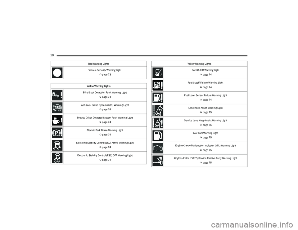
Vehicle Security Warning Light
Úpage 73
Yellow Warning Lights
Blind Spot Detection Fault Warning Light
Úpage 74
Anti-Lock Brake System (ABS) Warning Light
Úpage 74
Drowsy Driver Detected System Fault Warning Light
Úpage 74
Electric Park Brake Warning Light
Úpage 74
Electronic Stability Control (ESC) Active Warning Light
Úpage 74
Electronic Stability Control (ESC) OFF Warning Light
Úpage 74
Red Warning Lights
Fuel Cutoff Warning Light
Úpage 74
Fuel Cutoff Failure Warning Light
Úpage 74
Fuel Level Sensor Failure Warning Light
Úpage 74
Lane Keep Assist Warning Light
Úpage 75
Service Lane Keep Assist Warning Light
Úpage 75
Low Fuel Warning Light
Úpage 75
Engine Check/Malfunction Indicator (MIL) Warning Light
Úpage 75
Keyless Enter n’ Go™/Service Passive Entry Warning Light
Úpage 75
Yellow Warning Lights
23_GG_OM_EN_USC_t.book Page 10
Page 44 of 288
42GETTING TO KNOW YOUR VEHICLE
TURN SIGNALS
Move the multifunction lever up or down to activate the
turn signals. The arrows on each side of the instrument
cluster display flash to show proper operation.
Once the turn signal lever is activated, it will return to its
original position. To cancel the turn signal action, the lever
must be moved again or the turn in that direction must be
completed.
NOTE:If either light remains on and does not flash, or there is a
very fast flash rate, check for a defective outside light
bulb.
LANE CHANGE ASSIST
Lightly push the multifunction lever up or down, without
moving beyond the detent, and the turn signal will flash
three times then automatically turn off.
To turn off the flashing before the end of the cycle, move
the lever in the opposite direction until the first click
(about half way).
BATTERY SAVER FEATURE
To protect the battery, if the headlight switch is left in the
low beam or parking lights position when the ignition is
placed in the OFF position, the lights are deactivated after
eight minutes. The lights can also be turned off manually
by rotating the headlight switch to the O (off) position.
INTERIOR LIGHTS
INTERIOR COURTESY LIGHTS
Courtesy and dome lights are turned on when the front
doors are opened.
To protect the battery, the interior lights will turn off
automatically 15 minutes after the ignition is placed in the
OFF position, and no other activity in the vehicle has
occurred. This will occur if the interior lights were turned
on manually or are on because a door is open. This
includes the glove compartment light and the cargo area
light. To restore interior light operation, either place the
ignition in the ON/RUN position, or push the light switch on
and then back off.
Front Map Reading Lights
The front map/reading and overhead lights are mounted
in the overhead console. Each light can be turned on by
pushing the corresponding switch on the console. These
switches are backlit for nighttime visibility. To turn the
lights off, push the switch a second time.
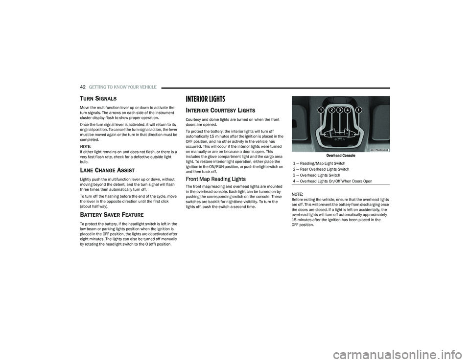
Overhead Console
NOTE:
Before exiting the vehicle, ensure that the overhead lights
are off. This will prevent the battery from discharging once
the doors are closed. If a light is left on accidentally, the
overhead lights will turn off automatically approximately
15 minutes after the ignition has been placed in the
OFF position. 1 — Reading/Map Light Switch
2 — Rear Overhead Lights Switch
3 — Overhead Lights Switch
4 — Overhead Lights On/Off When Doors Open
23_GG_OM_EN_USC_t.book Page 42
Page 72 of 288
70GETTING TO KNOW YOUR INSTRUMENT PANEL
DRIVER ASSIST
The instrument cluster display displays the current
Adaptive Cruise Control (ACC) and Lane Keep Assist (LKA)
system settings. The information displayed depends on
ACC system status.
The Instrument Cluster Display shows the status and
settings of the driving assistance Adaptive Cruise Control,
Lane Keep Assist and Active Driving Assist systems. Any
instant notifications are displayed via a pop-up screen.
The instrument cluster display displays the current LKA
system settings. The information displayed depends on
Lane Keep Assist system status and the conditions that
need to be met
Úpage 113.
STORED MESSAGES
Turn the Thumbwheel up and down until the Stored
Messages menu option is highlighted. Press the
Thumbwheel to enter and exit the Stored Messages.
Messages shown on the display via popup screens are
stored as long as they remain valid. You can view them
later in the central area of the “Messages” screen.
If multiple messages are present:
Press the Thumbwheel to access the message list.
Scroll through the messages by turning the Thumb -
wheel up or down. The presence or previous or next
message is indicated by gray dots.
BATTERY SAVER ON/BATTERY SAVER
M
ODE MESSAGE — ELECTRICAL LOAD
R
EDUCTION ACTIONS — IF EQUIPPED
This vehicle is equipped with an Intelligent Battery Sensor
(IBS) to perform additional monitoring of the electrical
system and status of the vehicle battery.
In cases when the IBS detects charging system failure, or
the vehicle battery conditions are deteriorating, electrical
load reduction actions will take place to extend the driving
time and distance of the vehicle. This is done by reducing
power to or turning off non-essential electrical loads.
Load reduction is only active when the engine is running.
It will display a message if there is a risk of battery
depletion to the point where the vehicle may stall due to
lack of electrical supply, or will not restart after the current
drive cycle.
These messages indicate the vehicle battery has a low
state of charge and continues to lose electrical charge at
a rate that the charging system cannot sustain.
NOTE:
The charging system is independent from load reduc -
tion. The charging system performs a diagnostic on the
charging system continuously.
If the Battery Charge Warning Light is on it may indicate
a problem with the charging system
Úpage 72. The electrical loads that may be switched off (if equipped),
and vehicle functions which can be effected by load
reduction:
Heated Seat/Vented Seats/Heated Wheel
Heated/Cooled Cup Holders — If Equipped
Rear Defroster And Heated Mirrors
HVAC System
150W Power Inverter System
Audio and Telematics System
Loss of the battery charge may indicate one or more of the
following conditions:
The charging system cannot deliver enough electrical
power to the vehicle system because the electrical
loads are larger than the capability of charging system.
The charging system is still functioning properly.
Turning on all possible vehicle electrical loads (e.g.
HVAC to max settings, exterior and interior lights, over -
loaded power outlets +12 Volts, 150W, USB ports)
during certain driving conditions (city driving, towing,
frequent stopping).
Installing options like additional lights, upfitter elec -
trical accessories, audio systems, alarms and similar
devices.
Unusual driving cycles (short trips separated by long
parking periods).
The vehicle was parked for an extended period of time
(weeks, months).
23_GG_OM_EN_USC_t.book Page 70
Page 77 of 288
GETTING TO KNOW YOUR INSTRUMENT PANEL75
Lane Keep Assist Warning Light —
If Equipped
The Lane Keep Assist Warning Light will be
solid yellow when the vehicle is approaching a
lane marker. The warning light will flash when
the vehicle is crossing the lane marker.
Service Lane Keep Assist Warning Light —
If Equipped
This warning light will illuminate when the Lane
Keep Assist system is not operating and
requires service. Please see an authorized
dealer.
Low Fuel Warning Light
The Low Fuel Warning Light will turn on when
low fuel is detected in the fuel tank.
Engine Check/Malfunction Indicator (MIL)
Warning Light
The MIL is a part of an Onboard Diagnostic
System called OBD II that monitors engine and
automatic transmission control systems. This
warning light will illuminate when the ignition is
in the ON/RUN position before engine start. If the bulb
does not come on when turning the ignition switch from
OFF to ON/RUN, have the condition checked promptly. Certain conditions, such as a loose or missing gas cap,
poor quality fuel, etc., may illuminate the light after engine
start. The vehicle should be serviced if the light stays on
through several typical driving styles. In most situations,
the vehicle will drive normally and will not require towing.
When the engine is running, the MIL may flash to alert
serious conditions that could lead to immediate loss of
power or severe catalytic converter damage. The vehicle
should be serviced by an authorized dealer as soon as
possible if this occurs.
Keyless Enter n’ Go™/Service Passive
Entry Warning Light
The telltale will illuminate in the event of
keyless system failure.
Contact an authorized dealer as soon as possible.
Service Forward Collision Warning (FCW)
Light — If Equipped
This warning light will illuminate to indicate a
fault in the Forward Collision Warning System.
Contact an authorized dealer for service
Úpage 162.
Service Stop/Start System Warning Light —
If Equipped
This warning light will illuminate when the
Stop/Start system is not functioning properly
and service is required. Contact an authorized
dealer for service.
Tire Pressure Monitoring System (TPMS)
Warning Light — If Equipped
The warning light switches on and a message is
displayed to indicate that the tire pressure is
lower than the recommended value and/or
that slow pressure loss is occurring. In these
cases, optimal tire duration and fuel consumption may not
be guaranteed.
Should one or more tires be in the condition mentioned
previously, the display will show the indications
corresponding to each tire.
WARNING!
A malfunctioning catalytic converter can reach higher
temperatures than in normal operating conditions.
This can cause a fire if you drive slowly or park over
flammable substances such as dry plants, wood,
cardboard, etc. This could result in death or serious
injury to the driver, occupants or others.
CAUTION!
Prolonged driving with the Malfunction Indicator Light
(MIL) on could cause damage to the vehicle control
system. It also could affect fuel economy and
driveability. If the MIL is flashing, severe catalytic
converter damage and power loss will soon occur.
Immediate service is required.
3
23_GG_OM_EN_USC_t.book Page 75
Page 98 of 288
96STARTING AND OPERATING
TO ACCELERATE FOR PASSING
While the Cruise Control is set, press the accelerator to
pass as you would normally. When the pedal is released,
the vehicle will return to the set speed.
Using Cruise Control On Hills
The transmission may downshift on hills to maintain the
vehicle set speed.
The Cruise Control system maintains speed up and down
hills. A slight speed change on moderate hills is normal.
On steep hills, a greater speed loss or gain may occur so it
may be preferable to drive without Cruise Control.
Setting The Following Distance In ACC
The specified following distance for ACC can be set by
varying the distance setting between four bars (longest),
three bars (long), two bars (medium) and one bar (short).
Using this distance setting and the vehicle speed, ACC
calculates and sets the distance to the vehicle ahead.
This distance setting will show in the instrument cluster
display.
Distance Settings
To decrease the distance setting, push the Distance
Setting Button and release. Each time the button is
pushed, the distance setting increases by one bar (longer).
Once the longest setting is reached, if the button is
pushed again it will be set to the shortest setting available.
If a slower moving vehicle is detected in the same lane,
the system will then adjust vehicle speed automatically to
maintain the distance setting, regardless of the set speed.
The vehicle will then maintain the set distance until:
The vehicle ahead accelerates to a speed above the
set speed.
The vehicle ahead moves out of your lane or view of the
sensor.
The distance setting is changed.
The system disengages
Úpage 94.
The maximum braking applied by ACC is limited; however,
the driver can always apply the brakes manually, if
necessary.
NOTE:The brake lights will illuminate whenever the ACC system
applies the brakes.
A Proximity Warning will alert the driver if ACC predicts that
its maximum braking level is not sufficient to maintain the
set distance. If this occurs, a visual alert “BRAKE!” (or
similar warning message) will flash in the instrument
cluster display and a chime will sound while ACC continues
to apply its maximum braking force.
NOTE:The “BRAKE!” screen in the instrument cluster display is a
warning for the driver to take action and does not neces -
sarily mean that the Forward Collision Warning system is
applying the brakes autonomously.
Overtake Aid
When driving with Adaptive Cruise Control (ACC) engaged
and following a vehicle, the system will provide an
additional acceleration up to the ACC set speed to assist
in passing the vehicle. This additional acceleration is
triggered when the driver utilizes the left turn signal and
will only be active when passing on the left hand side.
WARNING!
Cruise Control can be dangerous where the system
cannot maintain a constant speed. Your vehicle could
go too fast for the conditions, and you could lose control
and have an accident. Do not use Cruise Control in
heavy traffic or on roads that are winding, icy,
snow-covered or slippery.
1 — Longest Distance Setting (Four Bars)
2 — Medium Distance Setting (Two Bars)
3 — Long Distance Setting (Three Bars)
4 — Short Distance Setting (One Bar)
23_GG_OM_EN_USC_t.book Page 96
Page 103 of 288
STARTING AND OPERATING101
Setting The ACC Speed Using Confirmation Mode
When Confirmation Mode is selected, and the Traffic Sign
Recognition (TSR) system detects a new speed limit sign,
the driver will confirm this new speed by pushing
the SET switch upward briefly, then releasing. This
confirmation of the new speed must be done within
five seconds of a newly detected speed limit sign being
shown in the instrument cluster display.
Setting The ACC Speed Using Automatic Mode
When Automatic Mode is selected, the ACC system will
automatically adjust the speed setting when the TSR
system detects a new speed limit sign.
The driver can reject this new speed by pushing the SET
switch upward briefly, then releasing within five seconds
of the new speed limit sign being detected and the speed
being adjusted.
Set the desired following distance as you normally would
using the ACC system
Úpage 96.
ACTIVE DRIVING ASSIST SYSTEM —
IF EQUIPPED
OPERATION
The Active Driving Assist (ADA) system is combined with
the Adaptive Cruise Control (ACC) system, and centers the
vehicle in the driving lane while traveling at speeds up to
93 mph (150 km/h). For ACC system operating instructions and system
limitations, see
Úpage 92.
NOTE:
The driver should always obey traffic laws and speed
limits. Never drive above applicable speed limit restric -
tions.
The driver can override ADA at any time by braking,
accelerating, or steering the vehicle.
Just like ACC, ADA will maintain a set speed as long as the
set distance between your vehicle and the vehicle in front
is maintained. ADA will also keep your vehicle centered
between the lane lines, and monitor for other vehicles in
adjacent lanes by utilizing the Blind Spot Monitoring
sensors.
ADA uses sensors within the steering wheel to measure
driver attentiveness. ADA requires the driver’s hands on
the steering wheel at all times. The system will generally
aim to keep the vehicle centered in the lane, but when the
driver turns the steering wheel (e.g. to move farther away
from a large vehicle in an adjacent lane) the system will
reduce its control and enter "co-steering" mode. While in
co-steering mode, the system will provide reduced
assistance and allow the driver to control the path of the
vehicle. Once the driver stops providing input to the
steering wheel, the system will require a few seconds to
fully resume lane centering assistance, especially during
curves.
WARNING!
The Active Driving Assist (ADA) system is a convenience
system. It is not a substitute for active driver
involvement. It is always the driver’s responsibility to be
attentive of road traffic, weather conditions, vehicle
speed, distance to the vehicle ahead, position in the
lane compared to other vehicles, and brake operation
to ensure safe operation of the vehicle under all road
conditions. Your complete attention is always required
while driving to maintain safe control of your vehicle.
Failure to follow these warnings can result in a collision
and death or serious personal injury.
You should turn off the Active Driving Assist system:
When driving in complex driving situations
(e.g. urban environments, construction zones, etc.),
adverse weather or low visibility conditions (e.g. rain,
snow, fog, sleet, dust), or adverse road conditions
(e.g. heavy traffic, worn or missing lane markings,
etc.).
When entering a highway off-ramp, when driving on
roads that are icy, snow covered, or slippery.
When driving during difficult or uncertain conditions.
4
23_GG_OM_EN_USC_t.book Page 101
Page 104 of 288
102STARTING AND OPERATING
TURNING ACTIVE DRIVING ASSIST ON
O
R OFF
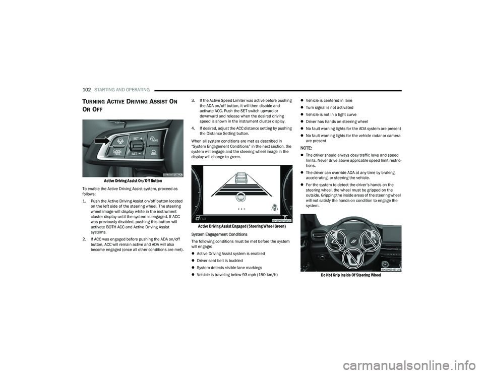
Active Driving Assist On/Off Button
To enable the Active Driving Assist system, proceed as
follows:
1. Push the Active Driving Assist on/off button located
on the left side of the steering wheel. The steering
wheel image will display white in the instrument
cluster display until the system is engaged. If ACC
was previously disabled, pushing this button will
activate BOTH ACC and Active Driving Assist
systems.
2. If ACC was engaged before pushing the ADA on/off button, ACC will remain active and ADA will also
become engaged (once all other conditions are met). 3. If the Active Speed Limiter was active before pushing
the ADA on/off button, it will then disable and
activate ACC. Push the SET switch upward or
downward and release when the desired driving
speed is shown in the instrument cluster display.
4. If desired, adjust the ACC distance setting by pushing the Distance Setting button.
When all system conditions are met as described in
“System Engagement Conditions” in the next section, the
system will engage and the steering wheel image in the
display will change to green.
Active Driving Assist Engaged (Steering Wheel Green)
System Engagement Conditions
The following conditions must be met before the system
will engage:
Active Driving Assist system is enabled
Driver seat belt is buckled
System detects visible lane markings
Vehicle is traveling below 93 mph (150 km/h)
Vehicle is centered in lane
Turn signal is not activated
Vehicle is not in a tight curve
Driver has hands on steering wheel
No fault warning lights for the ADA system are present
No fault warning lights for the vehicle radar or camera
are present
NOTE:
The driver should always obey traffic laws and speed
limits. Never drive above applicable speed limit restric -
tions.
The driver can override ADA at any time by braking,
accelerating, or steering the vehicle.
For the system to detect the driver’s hands on the
steering wheel, the wheel must be gripped on the
outside. Gripping the inside areas of the steering wheel
will not satisfy the hands-on condition to engage the
system.
Do Not Grip Inside Of Steering Wheel
23_GG_OM_EN_USC_t.book Page 102
Page 105 of 288
STARTING AND OPERATING103
System Deactivation
The system will be deactivated in any of the following
situations:
If the system has detected driver inattentiveness, and
has gone through all escalation warnings after hands
are no longer detected on the steering wheel
If the vehicle is driving in constant traffic
If lane markings are no longer detected
If the brake pedal is pressed or ACC system is deacti -
vated
If the Active Driving Assist on/off button is pushed
again (ADA will turn off)
If a turn signal is used (unless a target is in the blind
spot zone on the same side the turn signal is being
applied)
If the driver applies enough input to the steering wheel
If the driver’s seat belt is released
If the vehicle speed exceeds 93 mph (150 km/h)
If the Active Driving Assist on/off button is pushed
again (ADA will turn off)
If the Forward Collision Warning (FCW) system
becomes active and is providing warnings/braking
If there is glare from the sun on the vehicle’s camera
If the vehicle is driving on tight curves
If the camera has decreased visibility due to rain,
snow, etc.
If the driver quickly applies the accelerator pedal
NOTE:
Pushing the Active Driving Assist on/off button or deac -
tivating ACC will turn the system off. All other deactiva -
tion conditions will place the system back into the
“enabled” state with the steering wheel indicator
displayed in white until all engagement conditions are
met again.
When the system is deactivated, the system status
indicator lights will turn off, the LaneSense system will
return to its previous state, and ACC will disable.
INDICATIONS ON THE DISPLAY
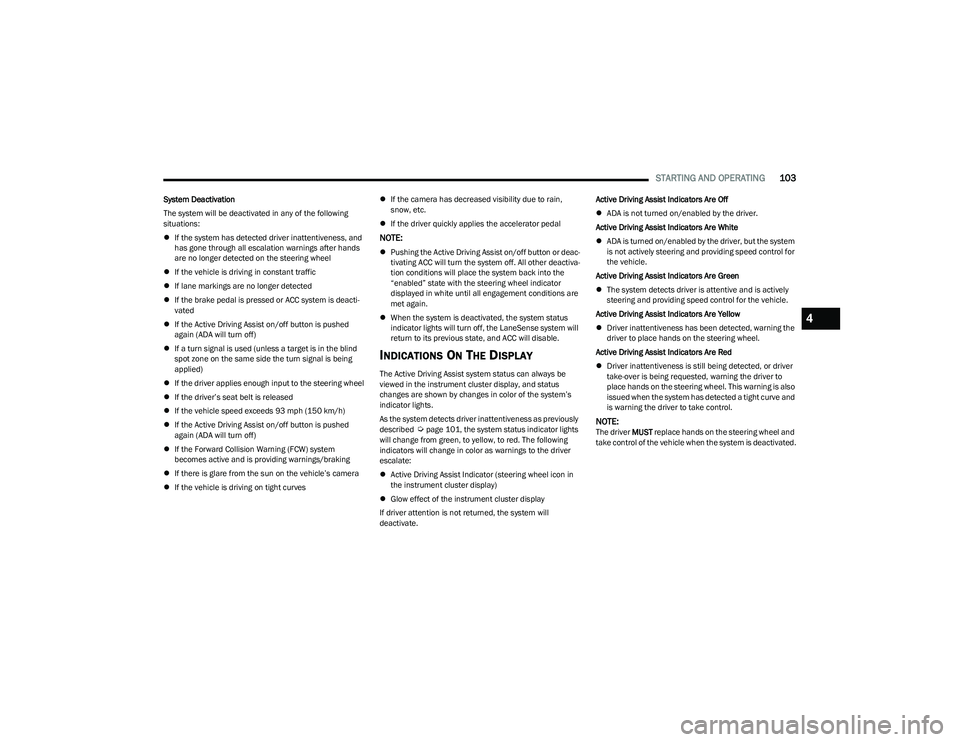
The Active Driving Assist system status can always be
viewed in the instrument cluster display, and status
changes are shown by changes in color of the system’s
indicator lights.
As the system detects driver inattentiveness as previously
described
Úpage 101, the system status indicator lights
will change from green, to yellow, to red. The following
indicators will change in color as warnings to the driver
escalate:
Active Driving Assist Indicator (steering wheel icon in
the instrument cluster display)
Glow effect of the instrument cluster display
If driver attention is not returned, the system will
deactivate. Active Driving Assist Indicators Are Off
ADA is not turned on/enabled by the driver.
Active Driving Assist Indicators Are White
ADA is turned on/enabled by the driver, but the system
is not actively steering and providing speed control for
the vehicle.
Active Driving Assist Indicators Are Green
The system detects driver is attentive and is actively
steering and providing speed control for the vehicle.
Active Driving Assist Indicators Are Yellow
Driver inattentiveness has been detected, warning the
driver to place hands on the steering wheel.
Active Driving Assist Indicators Are Red
Driver inattentiveness is still being detected, or driver
take-over is being requested, warning the driver to
place hands on the steering wheel. This warning is also
issued when the system has detected a tight curve and
is warning the driver to take control.NOTE:The driver MUST replace hands on the steering wheel and
take control of the vehicle when the system is deactivated.
4
23_GG_OM_EN_USC_t.book Page 103