park assist DODGE HORNET 2023 Owners Manual
[x] Cancel search | Manufacturer: DODGE, Model Year: 2023, Model line: HORNET, Model: DODGE HORNET 2023Pages: 288, PDF Size: 14.2 MB
Page 6 of 288
4
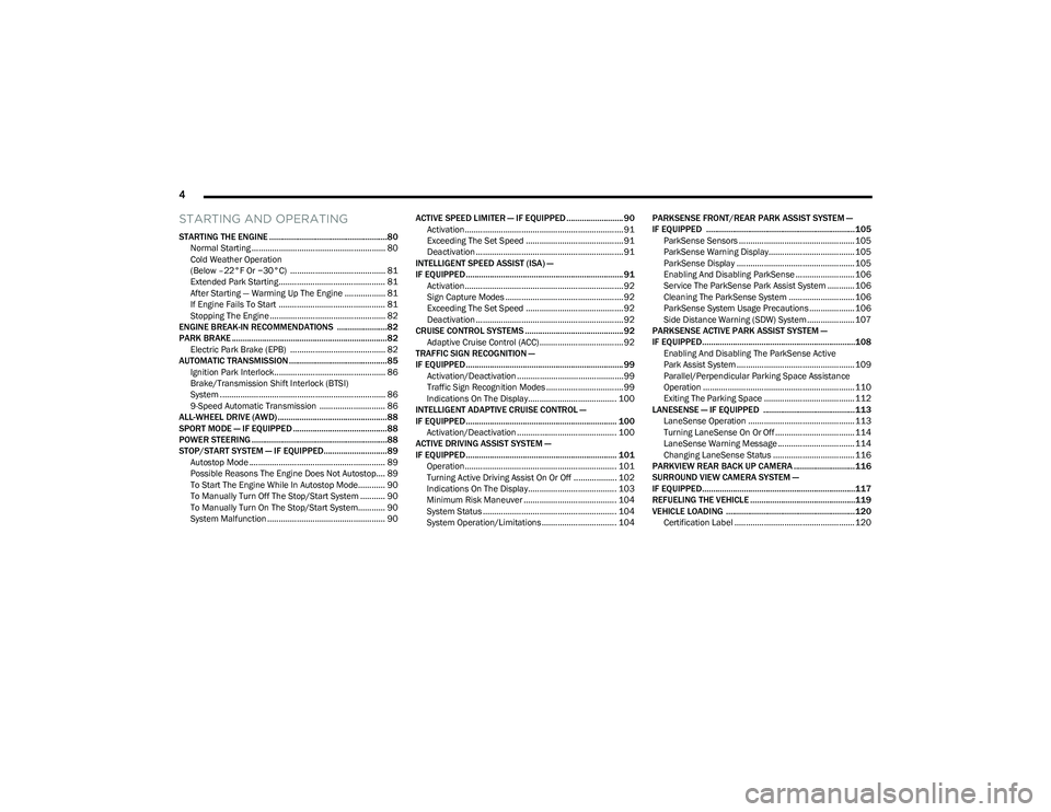
STARTING AND OPERATING
STARTING THE ENGINE ......................................................80
Normal Starting ........................................................... 80
Cold Weather Operation
(Below –22°F Or −30°C) .......................................... 81
Extended Park Starting............................................... 81
After Starting — Warming Up The Engine .................. 81
If Engine Fails To Start ............................................... 81
Stopping The Engine ................................................... 82
ENGINE BREAK-IN RECOMMENDATIONS .......................82
PARK BRAKE ....................................................................... 82 Electric Park Brake (EPB) .......................................... 82
AUTOMATIC TRANSMISSION .............................................85 Ignition Park Interlock................................................. 86
Brake/Transmission Shift Interlock (BTSI)
System ......................................................................... 86
9-Speed Automatic Transmission ............................. 86
ALL-WHEEL DRIVE (AWD) ..................................................88
SPORT MODE — IF EQUIPPED ...........................................88
POWER STEERING ..............................................................88
STOP/START SYSTEM — IF EQUIPPED.............................89 Autostop Mode ............................................................ 89
Possible Reasons The Engine Does Not Autostop.... 89
To Start The Engine While In Autostop Mode............ 90
To Manually Turn Off The Stop/Start System ........... 90
To Manually Turn On The Stop/Start System............ 90
System Malfunction .................................................... 90 ACTIVE SPEED LIMITER — IF EQUIPPED .......................... 90
Activation...................................................................... 91
Exceeding The Set Speed ........................................... 91
Deactivation ................................................................. 91
INTELLIGENT SPEED ASSIST (ISA) —
IF EQUIPPED ........................................................................ 91 Activation...................................................................... 92
Sign Capture Modes .................................................... 92
Exceeding The Set Speed ........................................... 92
Deactivation ................................................................. 92
CRUISE CONTROL SYSTEMS ............................................. 92 Adaptive Cruise Control (ACC)..................................... 92
TRAFFIC SIGN RECOGNITION —
IF EQUIPPED ........................................................................ 99 Activation/Deactivation ............................................... 99
Traffic Sign Recognition Modes .................................. 99
Indications On The Display....................................... 100
INTELLIGENT ADAPTIVE CRUISE CONTROL —
IF EQUIPPED ..................................................................... 100 Activation/Deactivation ............................................ 100
ACTIVE DRIVING ASSIST SYSTEM —
IF EQUIPPED ..................................................................... 101 Operation................................................................... 101
Turning Active Driving Assist On Or Off ................... 102
Indications On The Display....................................... 103
Minimum Risk Maneuver ......................................... 104
System Status ........................................................... 104
System Operation/Limitations................................. 104 PARKSENSE FRONT/REAR PARK ASSIST SYSTEM —
IF EQUIPPED ....................................................................105
ParkSense Sensors ................................................... 105
ParkSense Warning Display...................................... 105ParkSense Display .................................................... 105
Enabling And Disabling ParkSense .......................... 106
Service The ParkSense Park Assist System ............ 106
Cleaning The ParkSense System ............................. 106
ParkSense System Usage Precautions .................... 106
Side Distance Warning (SDW) System..................... 107
PARKSENSE ACTIVE PARK ASSIST SYSTEM —
IF EQUIPPED......................................................................108 Enabling And Disabling The ParkSense Active
Park Assist System .................................................... 109
Parallel/Perpendicular Parking Space Assistance
Operation ................................................................... 110Exiting The Parking Space ........................................ 112
LANESENSE — IF EQUIPPED .......................................... 113 LaneSense Operation ............................................... 113Turning LaneSense On Or Off ................................... 114
LaneSense Warning Message .................................. 114
Changing LaneSense Status .................................... 116
PARKVIEW REAR BACK UP CAMERA ............................ 116
SURROUND VIEW CAMERA SYSTEM —
IF EQUIPPED......................................................................117
REFUELING THE VEHICLE ................................................119
VEHICLE LOADING ...........................................................120 Certification Label ..................................................... 120
23_GG_OM_EN_USC_t.book Page 4
Page 12 of 288
10
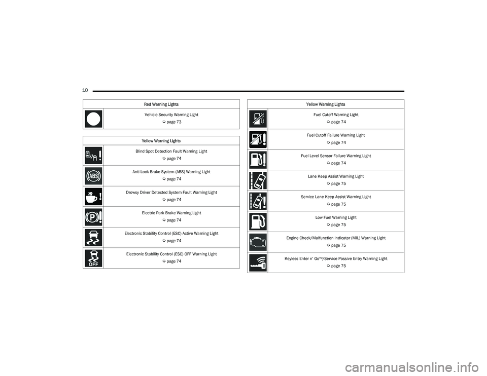
Vehicle Security Warning Light
Úpage 73
Yellow Warning Lights
Blind Spot Detection Fault Warning Light
Úpage 74
Anti-Lock Brake System (ABS) Warning Light
Úpage 74
Drowsy Driver Detected System Fault Warning Light
Úpage 74
Electric Park Brake Warning Light
Úpage 74
Electronic Stability Control (ESC) Active Warning Light
Úpage 74
Electronic Stability Control (ESC) OFF Warning Light
Úpage 74
Red Warning Lights
Fuel Cutoff Warning Light
Úpage 74
Fuel Cutoff Failure Warning Light
Úpage 74
Fuel Level Sensor Failure Warning Light
Úpage 74
Lane Keep Assist Warning Light
Úpage 75
Service Lane Keep Assist Warning Light
Úpage 75
Low Fuel Warning Light
Úpage 75
Engine Check/Malfunction Indicator (MIL) Warning Light
Úpage 75
Keyless Enter n’ Go™/Service Passive Entry Warning Light
Úpage 75
Yellow Warning Lights
23_GG_OM_EN_USC_t.book Page 10
Page 44 of 288
42GETTING TO KNOW YOUR VEHICLE
TURN SIGNALS
Move the multifunction lever up or down to activate the
turn signals. The arrows on each side of the instrument
cluster display flash to show proper operation.
Once the turn signal lever is activated, it will return to its
original position. To cancel the turn signal action, the lever
must be moved again or the turn in that direction must be
completed.
NOTE:If either light remains on and does not flash, or there is a
very fast flash rate, check for a defective outside light
bulb.
LANE CHANGE ASSIST
Lightly push the multifunction lever up or down, without
moving beyond the detent, and the turn signal will flash
three times then automatically turn off.
To turn off the flashing before the end of the cycle, move
the lever in the opposite direction until the first click
(about half way).
BATTERY SAVER FEATURE
To protect the battery, if the headlight switch is left in the
low beam or parking lights position when the ignition is
placed in the OFF position, the lights are deactivated after
eight minutes. The lights can also be turned off manually
by rotating the headlight switch to the O (off) position.
INTERIOR LIGHTS
INTERIOR COURTESY LIGHTS
Courtesy and dome lights are turned on when the front
doors are opened.
To protect the battery, the interior lights will turn off
automatically 15 minutes after the ignition is placed in the
OFF position, and no other activity in the vehicle has
occurred. This will occur if the interior lights were turned
on manually or are on because a door is open. This
includes the glove compartment light and the cargo area
light. To restore interior light operation, either place the
ignition in the ON/RUN position, or push the light switch on
and then back off.
Front Map Reading Lights
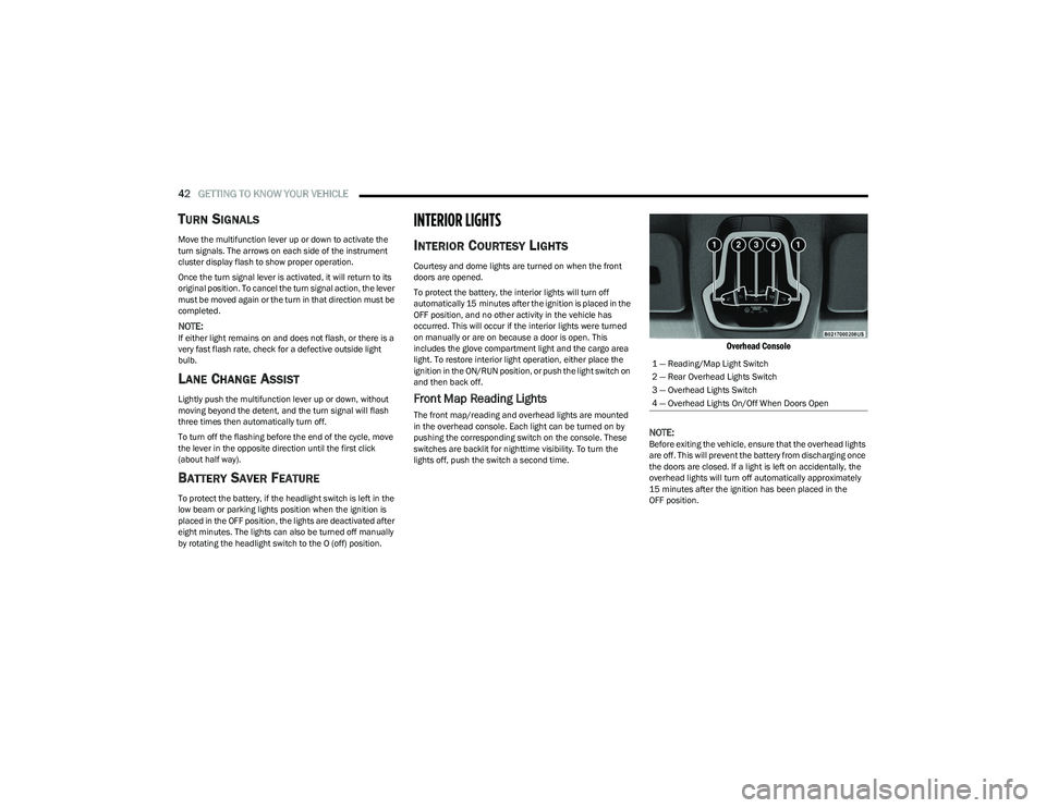
The front map/reading and overhead lights are mounted
in the overhead console. Each light can be turned on by
pushing the corresponding switch on the console. These
switches are backlit for nighttime visibility. To turn the
lights off, push the switch a second time.
Overhead Console
NOTE:
Before exiting the vehicle, ensure that the overhead lights
are off. This will prevent the battery from discharging once
the doors are closed. If a light is left on accidentally, the
overhead lights will turn off automatically approximately
15 minutes after the ignition has been placed in the
OFF position. 1 — Reading/Map Light Switch
2 — Rear Overhead Lights Switch
3 — Overhead Lights Switch
4 — Overhead Lights On/Off When Doors Open
23_GG_OM_EN_USC_t.book Page 42
Page 60 of 288
58GETTING TO KNOW YOUR VEHICLE
RE-INITIALIZATION PROCEDURE
Automatic operation of the sunroof must be re-initialized
in case of faulty sunroof operation. It may also be
necessary to re-initialize the sunroof after the vehicle’s
battery has been disconnected and then reconnected.
NOTE:The anti-pinch safety device is deactivated during the
re-initialization procedure.
Proceed as follows:
1. Place the ignition in the ON/RUN position.
2. Make sure the sunroof glass and the power sunshade
are fully closed. Release the sunroof close switch,
then push and hold it again within five seconds.
Continue to hold the switch while the sunshade fully
opens, the sunroof glass fully opens, followed by the
glass fully closing then the sunshade fully closing.
3. Release the switch once all of the operations stop. Re-initialization of the sunroof motor is now
complete.
NOTE:If the switch is released prior to full completion of the oper -
ations described, the entire re-initialization procedure
must be repeated from step 1.
4. Confirm express operations for the sunroof glass and sunshade are functional for opening and closing
operations.
SUNROOF MAINTENANCE
Use only a non-abrasive cleaner and a soft cloth to clean
the glass panel. Periodically check for and clear out any
debris that may have collected in the tracks.
HOOD
OPENING THE HOOD
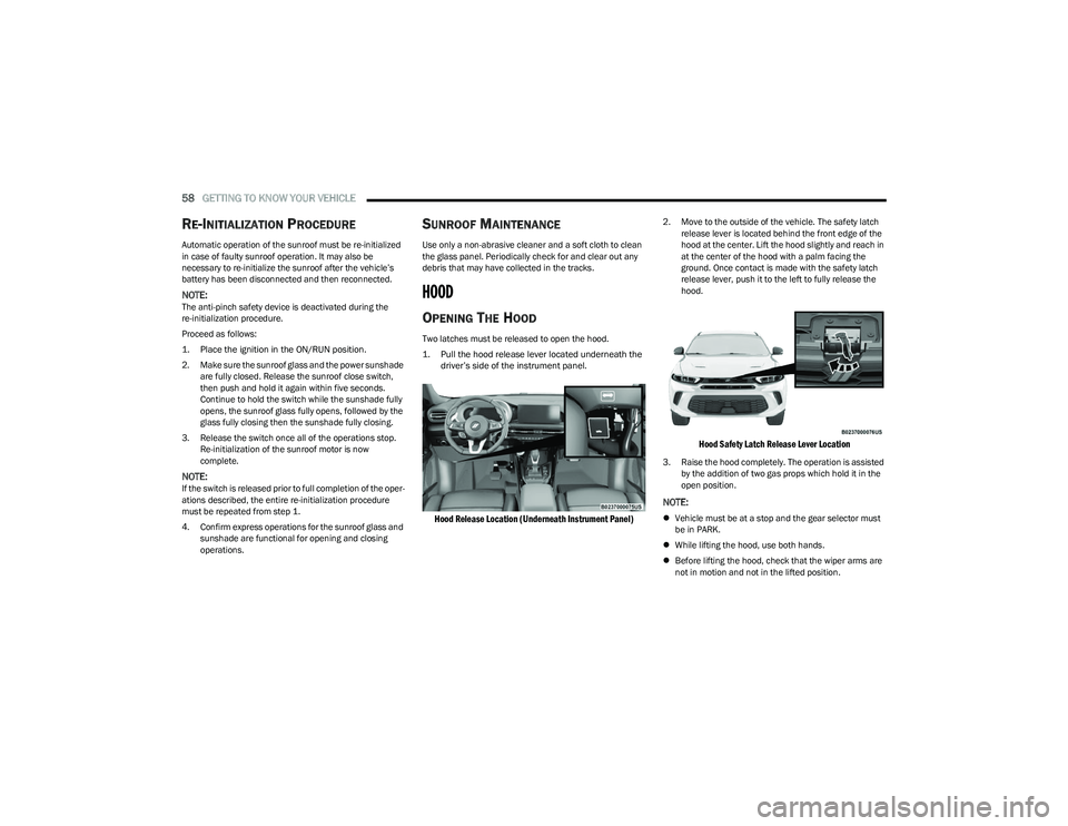
Two latches must be released to open the hood.
1. Pull the hood release lever located underneath the driver’s side of the instrument panel.
Hood Release Location (Underneath Instrument Panel)
2. Move to the outside of the vehicle. The safety latch release lever is located behind the front edge of the
hood at the center. Lift the hood slightly and reach in
at the center of the hood with a palm facing the
ground. Once contact is made with the safety latch
release lever, push it to the left to fully release the
hood.
Hood Safety Latch Release Lever Location
3. Raise the hood completely. The operation is assisted by the addition of two gas props which hold it in the
open position.
NOTE:
Vehicle must be at a stop and the gear selector must
be in PARK.
While lifting the hood, use both hands.
Before lifting the hood, check that the wiper arms are
not in motion and not in the lifted position.
23_GG_OM_EN_USC_t.book Page 58
Page 72 of 288
70GETTING TO KNOW YOUR INSTRUMENT PANEL
DRIVER ASSIST
The instrument cluster display displays the current
Adaptive Cruise Control (ACC) and Lane Keep Assist (LKA)
system settings. The information displayed depends on
ACC system status.
The Instrument Cluster Display shows the status and
settings of the driving assistance Adaptive Cruise Control,
Lane Keep Assist and Active Driving Assist systems. Any
instant notifications are displayed via a pop-up screen.
The instrument cluster display displays the current LKA
system settings. The information displayed depends on
Lane Keep Assist system status and the conditions that
need to be met
Úpage 113.
STORED MESSAGES
Turn the Thumbwheel up and down until the Stored
Messages menu option is highlighted. Press the
Thumbwheel to enter and exit the Stored Messages.
Messages shown on the display via popup screens are
stored as long as they remain valid. You can view them
later in the central area of the “Messages” screen.
If multiple messages are present:
Press the Thumbwheel to access the message list.
Scroll through the messages by turning the Thumb -
wheel up or down. The presence or previous or next
message is indicated by gray dots.
BATTERY SAVER ON/BATTERY SAVER
M
ODE MESSAGE — ELECTRICAL LOAD
R
EDUCTION ACTIONS — IF EQUIPPED
This vehicle is equipped with an Intelligent Battery Sensor
(IBS) to perform additional monitoring of the electrical
system and status of the vehicle battery.
In cases when the IBS detects charging system failure, or
the vehicle battery conditions are deteriorating, electrical
load reduction actions will take place to extend the driving
time and distance of the vehicle. This is done by reducing
power to or turning off non-essential electrical loads.
Load reduction is only active when the engine is running.
It will display a message if there is a risk of battery
depletion to the point where the vehicle may stall due to
lack of electrical supply, or will not restart after the current
drive cycle.
These messages indicate the vehicle battery has a low
state of charge and continues to lose electrical charge at
a rate that the charging system cannot sustain.
NOTE:
The charging system is independent from load reduc -
tion. The charging system performs a diagnostic on the
charging system continuously.
If the Battery Charge Warning Light is on it may indicate
a problem with the charging system
Úpage 72. The electrical loads that may be switched off (if equipped),
and vehicle functions which can be effected by load
reduction:
Heated Seat/Vented Seats/Heated Wheel
Heated/Cooled Cup Holders — If Equipped
Rear Defroster And Heated Mirrors
HVAC System
150W Power Inverter System
Audio and Telematics System
Loss of the battery charge may indicate one or more of the
following conditions:
The charging system cannot deliver enough electrical
power to the vehicle system because the electrical
loads are larger than the capability of charging system.
The charging system is still functioning properly.
Turning on all possible vehicle electrical loads (e.g.
HVAC to max settings, exterior and interior lights, over -
loaded power outlets +12 Volts, 150W, USB ports)
during certain driving conditions (city driving, towing,
frequent stopping).
Installing options like additional lights, upfitter elec -
trical accessories, audio systems, alarms and similar
devices.
Unusual driving cycles (short trips separated by long
parking periods).
The vehicle was parked for an extended period of time
(weeks, months).
23_GG_OM_EN_USC_t.book Page 70
Page 74 of 288
72GETTING TO KNOW YOUR INSTRUMENT PANEL
Vehicles equipped with the Anti-Lock Brake System (ABS)
are also equipped with Electronic Brake Force Distribution
(EBD). In the event of an EBD failure, the Brake Warning
Light will turn on along with the ABS Light. Immediate
repair to the ABS system is required.
Operation of the Brake Warning Light can be checked by
turning the ignition switch from the OFF position to the
ON/RUN position. The light should illuminate for
approximately two seconds. The light should then turn off
unless the parking brake is applied or a brake fault is
detected. If the light does not illuminate, have the light
inspected by an authorized dealer.
The light also will turn on when the parking brake is
applied with the ignition switch in the ON/RUN position.
NOTE:This light shows only that the parking brake is applied.
It does not show the degree of brake application.
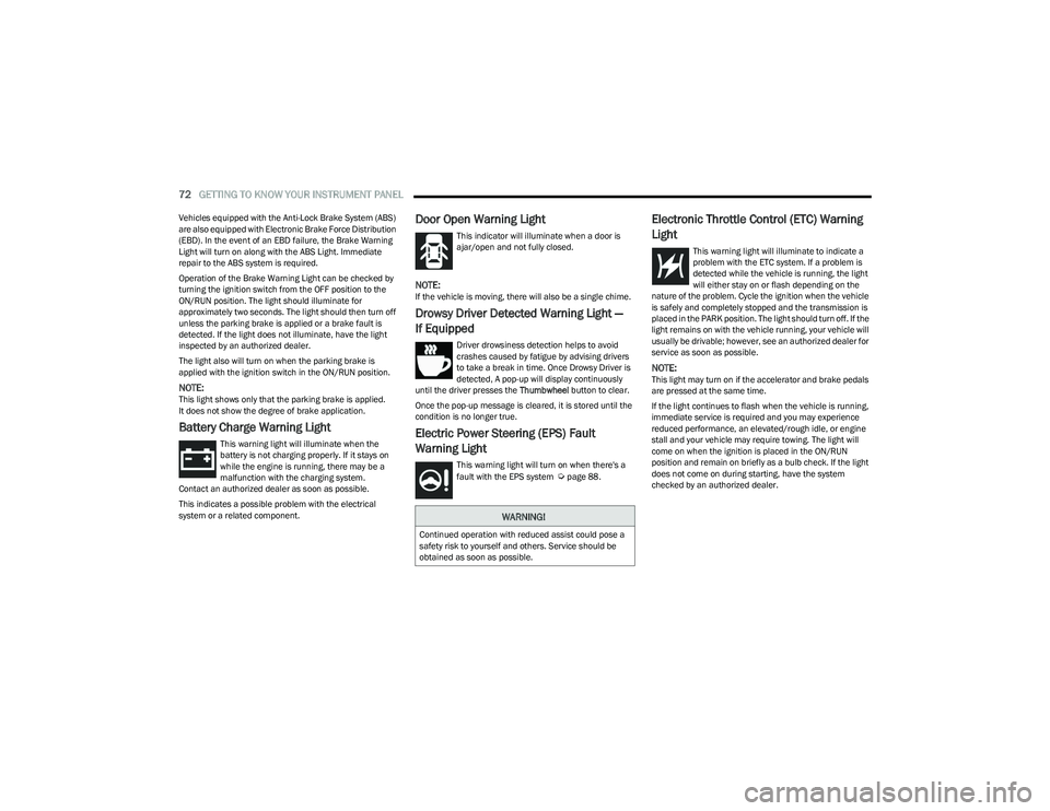
Battery Charge Warning Light
This warning light will illuminate when the
battery is not charging properly. If it stays on
while the engine is running, there may be a
malfunction with the charging system.
Contact an authorized dealer as soon as possible.
This indicates a possible problem with the electrical
system or a related component.
Door Open Warning Light
This indicator will illuminate when a door is
ajar/open and not fully closed.
NOTE:If the vehicle is moving, there will also be a single chime.
Drowsy Driver Detected Warning Light —
If Equipped
Driver drowsiness detection helps to avoid
crashes caused by fatigue by advising drivers
to take a break in time. Once Drowsy Driver is
detected, A pop-up will display continuously
until the driver presses the Thumbwheel button to clear.
Once the pop-up message is cleared, it is stored until the
condition is no longer true.
Electric Power Steering (EPS) Fault
Warning Light
This warning light will turn on when there's a
fault with the EPS system Úpage 88.
Electronic Throttle Control (ETC) Warning
Light
This warning light will illuminate to indicate a
problem with the ETC system. If a problem is
detected while the vehicle is running, the light
will either stay on or flash depending on the
nature of the problem. Cycle the ignition when the vehicle
is safely and completely stopped and the transmission is
placed in the PARK position. The light should turn off. If the
light remains on with the vehicle running, your vehicle will
usually be drivable; however, see an authorized dealer for
service as soon as possible.
NOTE:This light may turn on if the accelerator and brake pedals
are pressed at the same time.
If the light continues to flash when the vehicle is running,
immediate service is required and you may experience
reduced performance, an elevated/rough idle, or engine
stall and your vehicle may require towing. The light will
come on when the ignition is placed in the ON/RUN
position and remain on briefly as a bulb check. If the light
does not come on during starting, have the system
checked by an authorized dealer.
WARNING!
Continued operation with reduced assist could pose a
safety risk to yourself and others. Service should be
obtained as soon as possible.
23_GG_OM_EN_USC_t.book Page 72
Page 77 of 288
GETTING TO KNOW YOUR INSTRUMENT PANEL75
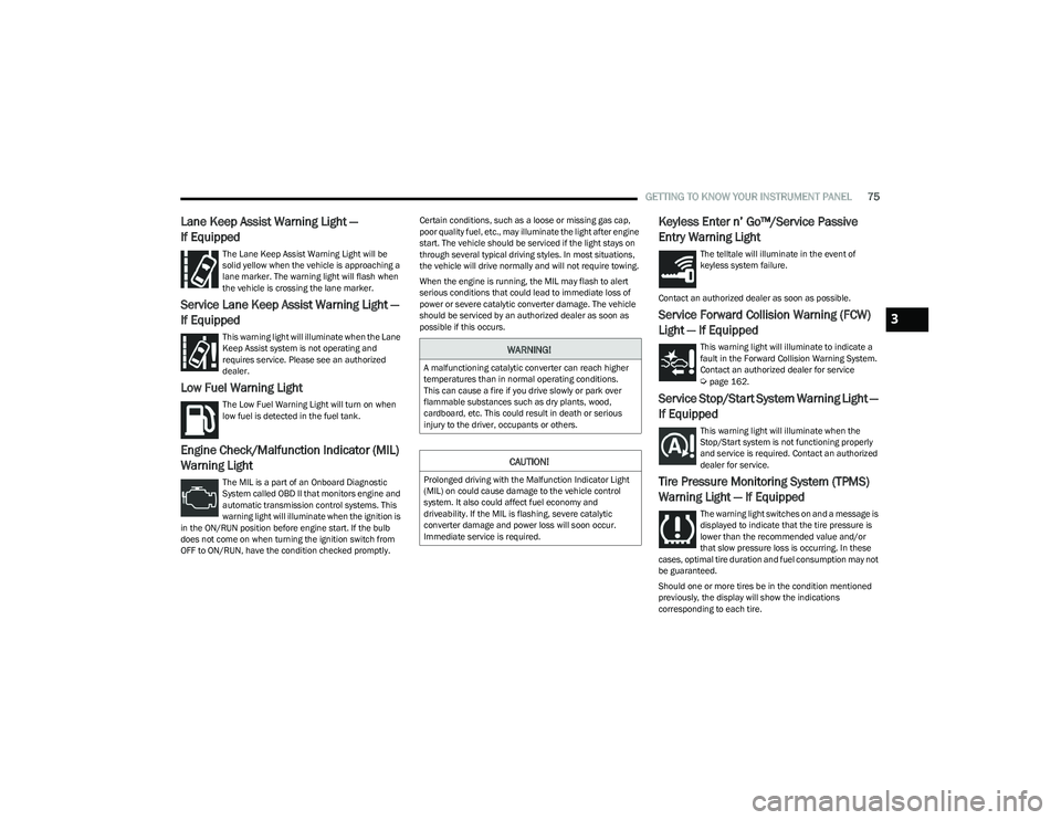
Lane Keep Assist Warning Light —
If Equipped
The Lane Keep Assist Warning Light will be
solid yellow when the vehicle is approaching a
lane marker. The warning light will flash when
the vehicle is crossing the lane marker.
Service Lane Keep Assist Warning Light —
If Equipped
This warning light will illuminate when the Lane
Keep Assist system is not operating and
requires service. Please see an authorized
dealer.
Low Fuel Warning Light
The Low Fuel Warning Light will turn on when
low fuel is detected in the fuel tank.
Engine Check/Malfunction Indicator (MIL)
Warning Light
The MIL is a part of an Onboard Diagnostic
System called OBD II that monitors engine and
automatic transmission control systems. This
warning light will illuminate when the ignition is
in the ON/RUN position before engine start. If the bulb
does not come on when turning the ignition switch from
OFF to ON/RUN, have the condition checked promptly. Certain conditions, such as a loose or missing gas cap,
poor quality fuel, etc., may illuminate the light after engine
start. The vehicle should be serviced if the light stays on
through several typical driving styles. In most situations,
the vehicle will drive normally and will not require towing.
When the engine is running, the MIL may flash to alert
serious conditions that could lead to immediate loss of
power or severe catalytic converter damage. The vehicle
should be serviced by an authorized dealer as soon as
possible if this occurs.
Keyless Enter n’ Go™/Service Passive
Entry Warning Light
The telltale will illuminate in the event of
keyless system failure.
Contact an authorized dealer as soon as possible.
Service Forward Collision Warning (FCW)
Light — If Equipped
This warning light will illuminate to indicate a
fault in the Forward Collision Warning System.
Contact an authorized dealer for service
Úpage 162.
Service Stop/Start System Warning Light —
If Equipped
This warning light will illuminate when the
Stop/Start system is not functioning properly
and service is required. Contact an authorized
dealer for service.
Tire Pressure Monitoring System (TPMS)
Warning Light — If Equipped
The warning light switches on and a message is
displayed to indicate that the tire pressure is
lower than the recommended value and/or
that slow pressure loss is occurring. In these
cases, optimal tire duration and fuel consumption may not
be guaranteed.
Should one or more tires be in the condition mentioned
previously, the display will show the indications
corresponding to each tire.
WARNING!
A malfunctioning catalytic converter can reach higher
temperatures than in normal operating conditions.
This can cause a fire if you drive slowly or park over
flammable substances such as dry plants, wood,
cardboard, etc. This could result in death or serious
injury to the driver, occupants or others.
CAUTION!
Prolonged driving with the Malfunction Indicator Light
(MIL) on could cause damage to the vehicle control
system. It also could affect fuel economy and
driveability. If the MIL is flashing, severe catalytic
converter damage and power loss will soon occur.
Immediate service is required.
3
23_GG_OM_EN_USC_t.book Page 75
Page 90 of 288
88STARTING AND OPERATING
In the event of a momentary problem, the transmission
can be reset to regain all forward gears by performing the
following steps:
1. Stop the vehicle.
2. Shift the transmission into PARK (P), if possible. If
not, shift the transmission to NEUTRAL.
3. Push and hold the ignition until the engine turns off.
4. Wait approximately 30 seconds.
5. Restart the engine.
6. Shift into the desired gear range. If the problem is no longer detected, the transmission will return to
normal operation.
NOTE:Even if the transmission can be reset, we recommend that
you visit an authorized dealer at your earliest possible
convenience. An authorized dealer has diagnostic
equipment to assess the condition of your transmission.
If the transmission cannot be reset, authorized dealer
service is required.
TORQUE CONVERTER CLUTCH
A feature designed to improve fuel economy has been
included in the automatic transmission on your vehicle.
A clutch within the torque converter engages
automatically at calibrated speeds. This may result in a
slightly different feeling or response during normal
operation in the upper gears. When the vehicle speed
drops or during some accelerations, the clutch
automatically disengages.
NOTE:The torque converter clutch will not engage until the
engine and/or transmission is warm (usually after 1 to
3 miles [2 to 5 km] of driving). Because the engine speed
is higher when the torque converter clutch is not engaged,
it may seem as if the transmission is not shifting properly
when the vehicle is cold. This is normal. The torque
converter clutch will function normally once the powertrain
is sufficiently warm.
ALL-WHEEL DRIVE (AWD)
This feature provides on-demand All-Wheel Drive (AWD).
The system is automatic with no driver inputs or additional
driving skills required. Under normal driving conditions,
the front wheels provide most of the traction. If the front
wheels begin to lose traction, power is shifted
automatically to the rear wheels. The greater the front
wheel traction loss, the greater the power transfer to the
rear wheels.
Additionally, on dry pavement under heavy throttle input
(where one may have no wheel spin), torque will be sent to
the rear in a preemptive effort to improve vehicle launch
and performance characteristics.
SPORT MODE — IF EQUIPPED
Your vehicle is equipped with a SPORT Mode feature. The
engine, transmission, and steering systems are all set to
their SPORT settings. SPORT Mode will provide improved
throttle response and modified transmission shift points
for an enhanced driving experience, as well as greater
amount of steering feel.
This mode may be activated and deactivated by pushing
the SPORT button on the steering wheel. For PHEV
versions the SPORT button is located below the STOP/
START button.
POWER STEERING
The electric power steering system will provide increased
vehicle response and ease of maneuverability. The electric
power steering system adapts to different driving conditions.
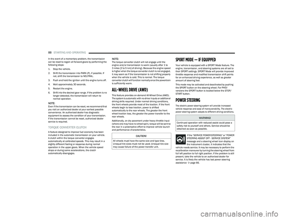
If the “SERVICE POWER STEERING” or “POWER
STEERING ASSIST OFF - SERVICE SYSTEM”
message and a steering wheel icon display on
the instrument cluster, it indicates that the
vehicle needs service. It may be necessary to perform the
recalibration maneuver by turning the steering wheel from
full left position to full right position. If the problem is still
present, take the vehicle to an authorized dealer for
service. It is likely the vehicle has lost power steering
assistance
Úpage 66.
CAUTION!
All wheels must have the same size and type tires.
Unequal tire sizes must not be used. Unequal tire size
may cause failure of the power transfer unit.
WARNING!
Continued operation with reduced assist could pose a
safety risk to yourself and others. Service should be
obtained as soon as possible.
23_GG_OM_EN_USC_t.book Page 88
Page 91 of 288
STARTING AND OPERATING89
If the “POWER STEERING SYSTEM HOT -
PERFORMANCE MAY BE LIMITED” message
and a steering wheel icon display on the
instrument cluster, it indicates that extreme
steering maneuvers may have occurred, which caused an
over temperature condition in the electric power steering
system. You will lose power steering assistance
momentarily until the over temperature condition no
longer exists. Once driving conditions are safe, pull over
and let the vehicle idle for a few moments until the light
turns off
Úpage 66.
NOTE:
Even if the power steering system is no longer opera -
tional, it is still possible to steer the vehicle. Under
these conditions there will be a substantial increase in
steering effort, especially at low speeds and during
parking maneuvers.
If the condition persists, see an authorized dealer for
service.
STOP/START SYSTEM — IF EQUIPPED
The Stop/Start function is designed to reduce fuel
consumption. The system will stop the engine
automatically during a vehicle stop if the required
conditions are met. Releasing the brake pedal or pressing
the accelerator pedal will automatically restart the engine.
This vehicle has been upgraded with a heavy-duty starter,
enhanced battery, and other upgraded engine parts, to
handle the additional engine starts.
AUTOSTOP MODE
The Stop/Start feature is enabled after every normal
customer engine start. At that time, the system will go into
STOP/START READY.
To Activate The Autostop Mode, The Following Must Occur:
The system must be in STOP/START READY state. A
“STOP/START READY” message will be displayed in the
instrument cluster display within the Stop/Start
section
Úpage 66.
The vehicle must be completely stopped.
The gear selector must be in a forward gear and the
brake pedal pressed.
The engine will shut down, the tachometer will move to the
zero position, and the Stop/Start telltale will illuminate
indicating you are in Autostop. Customer settings will be
maintained upon return to an engine-running condition.
POSSIBLE REASONS THE ENGINE DOES
N
OT AUTOSTOP
Prior to engine shut down, the system will check many
safety and comfort conditions to see if they are fulfilled.
Detailed information about the operation of the Stop/Start
system may be viewed in the instrument cluster display
Stop/Start Screen. In the following situations the engine
will not stop:
Driver’s seat belt is not buckled.
Driver’s door is not closed.
Battery temperature is too warm or cold.
Battery charge is low.
The vehicle is on a steep grade.
Cabin heating or cooling is in process and an accept -
able cabin temperature has not been achieved.
HVAC is set to full defrost mode at a high blower speed.
HVAC is set to MAX A/C.
Engine has not reached normal operating temperature.
The transmission is not in a forward gear.
Hood is open.
Brake pedal is not pressed with sufficient pressure.
Accelerator pedal input.
Engine temperature is too high.
5 mph (8 km/h) threshold has not been achieved from
previous Autostop.
Steering angle beyond threshold.
Adaptive Cruise Control is on and speed is set.
It may be possible for the vehicle to be driven several
times without the Stop/Start system going into a STOP/
START READY state under more extreme conditions of the
items listed previously.
4
23_GG_OM_EN_USC_t.book Page 89
Page 93 of 288
STARTING AND OPERATING91
NOTE:
The Mode button also activates the Adaptive Cruise
Control (ACC) system. Pushing the Mode button will
switch between activating the Active Speed Limiter or
the Adaptive Cruise Control systems. They cannot be
active at the same time.
The Active Speed Limiter can be set while the vehicle is
in motion, or with the gear selector in the PARK posi -
tion.
ACTIVATION
To activate the feature, push the Mode button located on
the left side of the steering wheel. A white indicator light in
the instrument cluster display to signal that Active Speed
Limiter has been enabled.
After the Active Speed Limiter system is enabled, activate
the system by setting the speed limit of the vehicle by
pushing the SET switch upward or downward.
Pushing the SET switch upward or downward to the first
detent, and releasing, will result in a 1 mph (1 km/h)
speed adjustment. Each subsequent movement of the
switch to the first detent will result in an adjustment of
1 mph (1 km/h).
If the switch is pushed upward or downward briefly to
the second detent, the set speed will adjust in 5 mph
(10 km/h) increments. The new set speed is reflected in
the instrument cluster display. If the switch is held upward or downward, the set speed
will continue to adjust until the switch is released.
NOTE:
Once the speed as been set, the indicator light in the
instrument cluster display will change to green.
If Adaptive Cruise Control (ACC) or the Active Speed
Limiter is active when the ignition is placed in the
OFF position, it will remain activated when the vehicle
is started again.
ACC will be unavailable while the Active Speed Limiter
is in use.
EXCEEDING THE SET SPEED
By fully pressing the accelerator pedal, the programmed
maximum speed can be exceeded while the device is
active.
In the event that the Active Speed Limiter set value is
exceeded manually with a driver acceleration, an audible
chime will sound. The indicator light will flash rapidly, and
a message will appear in the instrument cluster display.
The feature will remain disabled until the vehicle speed
drops below the set Active Speed Limiter value, where it
will reactivate automatically.
NOTE:While driving at a higher speed than previously set, the set
limit can be updated by pushing the SET switch upward or
downward to the new desired speed.
DEACTIVATION
To turn off Active Speed Limiter, push the Mode button
again. The indicator light in the instrument cluster display
will no longer be illuminated to confirm that the feature
has been turned off, and Adaptive Cruise Control will be
active.
The Active Speed Limiter can be deactivated by pressing
the CANC button. In this case, the system is not completely
turned off, and the driver can reactivate the Active Speed
Limiter by pressing the RES button to the previously set
speed.
INTELLIGENT SPEED ASSIST (ISA) —
IF EQUIPPED
The Intelligent Speed Assist (ISA) system
combines the Active Speed Limiter and
Traffic Sign Recognition (TSR) systems to
automatically adjust the maximum speed of
the vehicle based on detected speed limit signs.
When the ISA system is activated, the maximum speed of
the vehicle will be adjusted according to the detected
traffic signs depending on the Sign Capture Mode selected
within Uconnect Settings
Úpage 130.
4
23_GG_OM_EN_USC_t.book Page 91