tow DODGE JOURNEY 2010 1.G Owner's Manual
[x] Cancel search | Manufacturer: DODGE, Model Year: 2010, Model line: JOURNEY, Model: DODGE JOURNEY 2010 1.GPages: 88, PDF Size: 12.49 MB
Page 55 of 88
• We recommend you do not continue driving if the charging system light is on. Have thevehicle serviced immediately.
- Oil Pressure Warning Light
• This light indicates low engine oil pressure. If the light turns on while driving, stop thevehicle and shut off the engine as soon as possible. A chime will sound for four
minutes when this light turns on.
• We recommend you do not operate the vehicle or engine damage will occur. Have the vehicle serviced immediately.
- Anti-Lock Brake (ABS) Light
• This light monitors the Anti-Lock Brake System (ABS).
• If the light is not on during starting, stays on, or turns on while driving, we recommendyou do not operate the vehicle. Hav e the vehicle serviced immediately.
- Electronic Throttle Control (ETC) Light
• This light informs you of a problem with the Electronic Throttle Control (ETC) system.
• If a problem is detected, the light will come on while the engine is running. Cycle the
ignition when the vehicle has completely stopped and the shift lever is placed in the
PARK position; the light should turn off.
• If the light remains lit with the engine running, your vehicle will usually be drivable; however, see an authorized dealer for service as soon as possible. If the light is
flashing when the engine is running, immedi ate service is required and you may
experience reduced performance, an elevat ed/rough idle or engine stall and your
vehicle may require towing.
- Airbag Warning Light
• If the light is not on during starting, stays on, or turns on while driving, we recommend you do not operate the vehicle. Hav e the vehicle serviced immediately.
- All-Wheel Drive (AWD) Failure Indicator Light
• If the light stays on or comes on during driving, it means that the AWD system is not
functioning properly and that service is required. We recommend you drive to the
nearest service center as soon as possible.
Fuel Cap/Loose Gas Cap Message
• If a “gas cap” message (shown as gASCAP) appears, tighten the gas cap until a“clicking” sound is heard.
• Press the odometer reset button to turn the message off.
• If the message continues to appear for mor e than three days after tightening the gas
cap, see your authorized dealer.
53
WHAT TO DO IN EMERGENCIES
Page 58 of 88
Jack Location
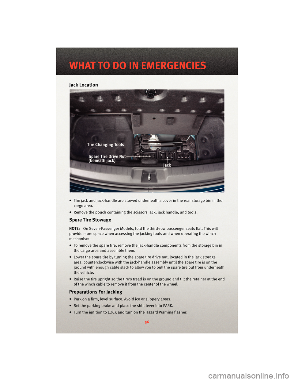
• The jack and jack-handle are stowed underneath a cover in the rear storage bin in thecargo area.
• Remove the pouch containing the scissors jack, jack handle, and tools.
Spare Tire Stowage
NOTE:On Seven-Passenger Models, fold the third-row passenger seats flat. This will
provide more space when accessing the jacking tools and when operating the winch
mechanism.
• To remove the spare tire, remove the jack-handle components from the storage bin in the cargo area and assemble them.
• Lower the spare tire by turning the spare tire drive nut, located in the jack storage area, counterclockwise with the jack-h andle assembly until the spare tire is on the
ground with enough cable slack to allow you to pull the spare tire out from underneath
the vehicle.
• Raise the tire upright so the tire’s tread is o n the ground and tilt the retainer at the end
of the winch cable to remove it from the center of the wheel.
Preparations For Jacking
• Park on a firm, level surface. Avoid ice or slippery areas.
• Set the parking brake and place the shift lever into PARK.
• Turn the ignition to LOCK and turn on the Hazard Warning flasher.
WHAT TO DO IN EMERGENCIES
56
Page 60 of 88
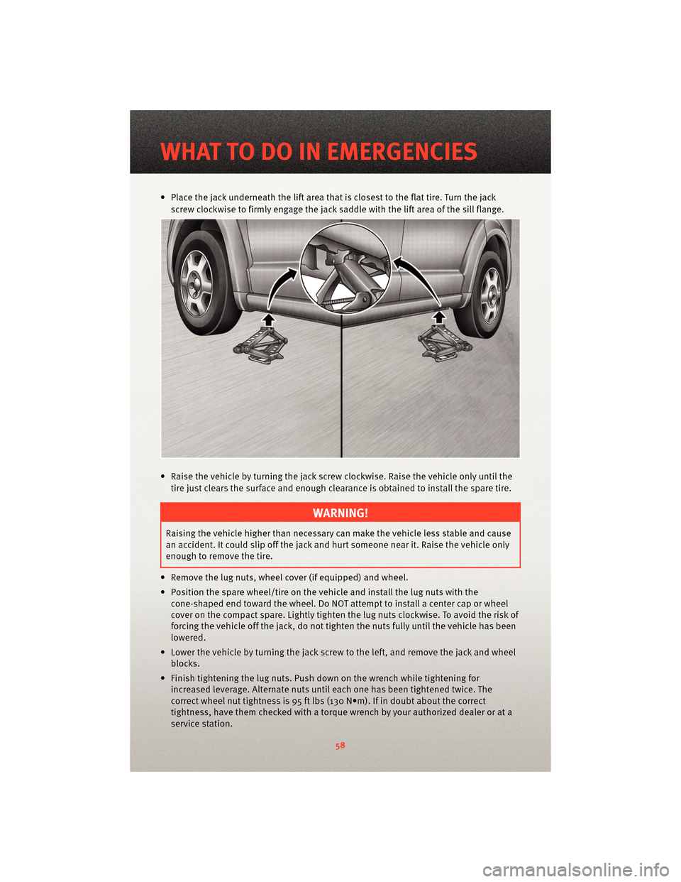
• Place the jack underneath the lift area that is closest to the flat tire. Turn the jackscrew clockwise to firmly engage the jack saddle with the lift area of the sill flange.
• Raise the vehicle by turning the jack screw clockwise. Raise the vehicle only until the tire just clears the surface and enough clearance is obtained to install the spare tire.
WARNING!
Raising the vehicle higher than necessary can make the vehicle less stable and cause
an accident. It could slip off the jack and hurt someone near it. Raise the vehicle only
enough to remove the tire.
• Remove the lug nuts, wheel cover (if equipped) and wheel.
• Position the spare wheel/tire on the vehicle and install the lug nuts with the cone-shaped end toward the wheel. Do NOT attempt to install a center cap or wheel
cover on the compact spare. Lightly tighten the lug nuts clockwise. To avoid the risk of
forcing the vehicle off the jack, do not tighten the nuts fully until the vehicle has been
lowered.
• Lower the vehicle by turning the jack screw to the left, and remove the jack and wheel blocks.
• Finish tightening the lug nuts. Push do wn on the wrench while tightening for
increased leverage. Alternate nuts until each one has been tightened twice. The
correct wheel nut tightness is 95 ft lbs (130 N•m). If in doubt about the correct
tightness, have them checked with a tor que wrench by your authorized dealer or at a
service station.
WHAT TO DO IN EMERGENCIES
58
Page 61 of 88
WARNING!
A loose tire or jack, thrown forward in a collision or hard stop, could endanger the
occupants of the vehicle. Always stow the jack parts and the spare tire in the places
provided.
• Place the deflated (flat) tire and compact spare tire cover assembly in the rear cargo area. Do not stow the deflated tire in the spare tire location. Have the full-sized tire
repaired or replaced as soon as possible.
• To stow the winch cable and retainer, fit the assembled jack-handle over the winch drive nut. Rotate the jack-handle assemb ly clockwise until you hear the winch
mechanism click three times.
• Secure the jack and tools in their proper locations.
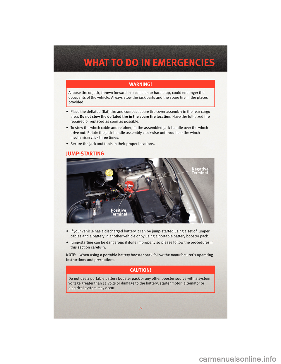
JUMP-STARTING
• If your vehicle has a discharged battery it can be jump-started using a set of jumper cables and a battery in another vehicle or by using a portable battery booster pack.
• Jump-starting can be dangerous if done improperly so please follow the procedures in this section carefully.
NOTE: When using a portable battery booster pack follow the manufacturer's operating
instructions and precautions.
CAUTION!
Do not use a portable battery booster pack or any other booster source with a system
voltage greater than 12 Volts or damage to the battery, starter motor, alternator or
electrical system may occur.
59
WHAT TO DO IN EMERGENCIES
Page 64 of 88
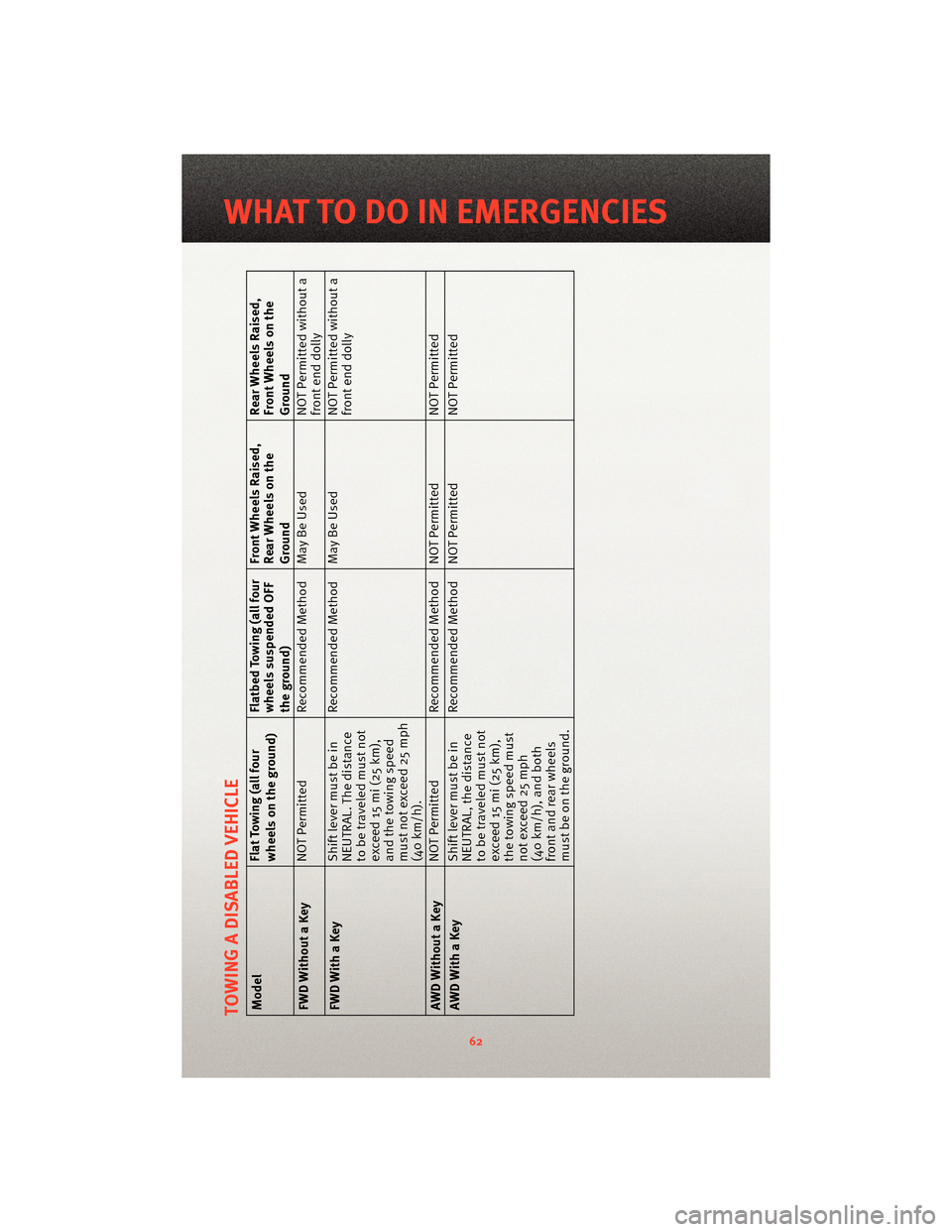
TOWING A DISABLED VEHICLEModelFlat Towing (all four
wheels on the ground)Flatbed Towing (all four
wheels suspended OFF
the ground)Front Wheels Raised,
Rear Wheels on the
GroundRear Wheels Raised,
Front Wheels on the
Ground
FWD Without a Key NOT Permitted
Recommended Method May Be Used NOT Permitted without a
front end dolly
FWD With a Key Shift lever must be in
NEUTRAL. The distance
to be traveled must not
exceed 15 mi (25 km),
and the towing speed
must not exceed 25 mph
(40 km/h).Recommended Method May Be Used
NOT Permitted without a
front end dolly
AWD Without a Key NOT Permitted
Recommended Method NOT Permitted NOT Permitted
AWD With a Key Shift lever must be in
NEUTRAL, the distance
to be traveled must not
exceed 15 mi (25 km),
the towing speed must
not exceed 25 mph
(40 km/h), and both
front and rear wheels
must be on the ground.Recommended Method NOT Permitted
NOT Permitted
62
WHAT TO DO IN EMERGENCIES
Page 72 of 88
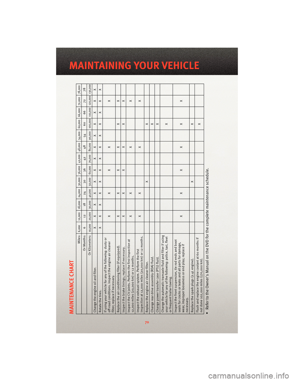
MAINTENANCE CHART
Miles:
6,000 12,000 18,000 24,000 30,000 36,000 42,000 48,000 54,000 60,000 66,000 72,000 78,000
Or Months: 6 12 18 24 30 36 42 48 54 60 66 72 78
Or Kilometers:
10,000 20,000 30,000 40,000 50,000 60,000 70,000 80,000 90,000 100,000 110,000 120,000 130,000
Change the engine oil and filter. XXXXXXXXXXXXX
Rotatethetires. XXXXXXXXXXXXX
If using your vehicle for any of the following: dusty or
off-road conditions. Inspect the engine air cleaner
filter; replace if necessary. XXXX
X
Replace the air conditioning filter (if equipped). XXXXXX
Inspect the brake linings; replace if necessary. XXXXXX
Inspect the CV joints. Perform the first inspection at
12,000 miles (20,000 km) or 12 months. X
XXX
Inspect the exhaust system. Perform the first
inspection at 12,000 miles (20,000 km) or 12 months. X
XXX
Replace the engine air cleaner filter. XX
Change rear drive assembly (RDA) fluid. X
Change power transfer case (PTU) fluid. X
Change the automatic transaxl e fluid and filter if using
your vehicle for any of the following: police, taxi, fleet
or frequent trailer towing. X
Inspect the front suspe nsion, tie rod ends and boot
seals for cracks or leaks and all parts for damage,
wear, improper looseness or end play; replace if
necessary. XXXXXX
Replace the spark plugs (2.4L engine). XX
Flush and replace the engine coolant at 60 months if
not done 102,000 miles (170,000 km). X• Refer to the Owner's Manual on the DVD for the complete maintenance schedule.
70
MAINTAINING YOUR VEHICLE
Page 75 of 88
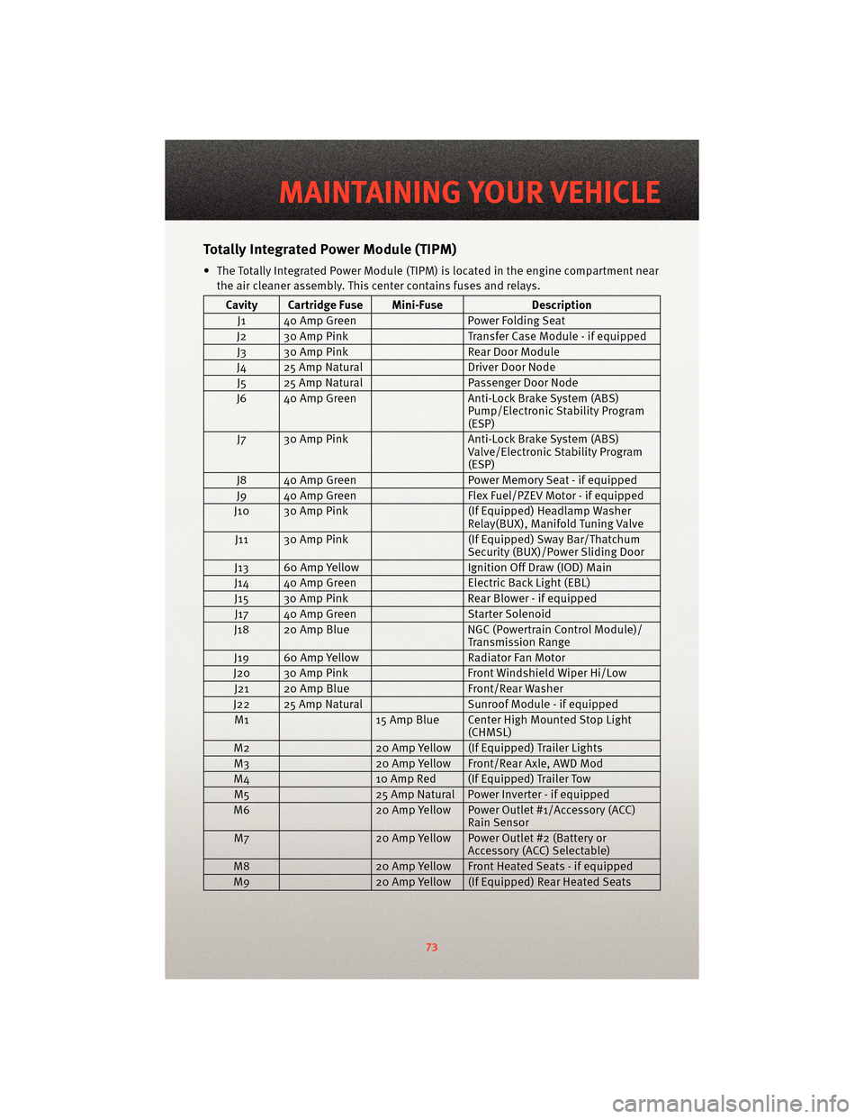
TotallyIntegrated Power Module (TIPM)
• The Totally Integrated Power Module (TIPM) is located in the engine compartment near
the air cleaner assembly. This center contains fuses and relays.
Cavity Cartridge Fuse Mini-Fuse Description
J1 40 Amp Green Power Folding Seat
J2 30 Amp Pink Transfer Case Module - if equipped
J3 30 Amp Pink Rear Door Module
J4 25 Amp Natural Driver Door Node
J5 25 Amp Natural Passenger Door Node
J6 40 Amp Green Anti-Lock Brake System (ABS)
Pump/Electronic Stability Program
(ESP)
J7 30 Amp Pink Anti-Lock Brake System (ABS)
Valve/Electronic Stability Program
(ESP)
J8 40 Amp Green Power Memory Seat - if equipped
J9 40 Amp Green Flex Fuel/PZEV Motor - if equipped
J10 30 Amp Pink (If Equipped) Headlamp Washer
Relay(BUX), Manifold Tuning Valve
J11 30 Amp Pink (If Equipped) Sway Bar/Thatchum
Security (BUX)/Power Sliding Door
J13 60 Amp Yellow Ignition Off Draw (IOD) Main
J14 40 Amp Green Electric Back Light (EBL)
J15 30 Amp Pink Rear Blower - if equipped
J17 40 Amp Green Starter Solenoid
J18 20 Amp Blue NGC (Powertrain Control Module)/
Transmission Range
J19 60 Amp Yellow Radiator Fan Motor
J20 30 Amp Pink Front Windshield Wiper Hi/Low
J21 20 Amp Blue Front/Rear Washer
J22 25 Amp Natural Sunroof Module - if equipped
M1 15 Amp Blue Center High Mounted Stop Light
(CHMSL)
M2 20 Amp Yellow (If Equipped) Trailer Lights
M3 20 Amp Yellow Front/Rear Axle, AWD Mod
M4 10 Amp Red (If Equipped) Trailer Tow
M5 25 Amp Natural Power Inverter - if equipped
M6 20 Amp Yellow Power Outlet #1/Accessory (ACC)
Rain Sensor
M7 20 Amp Yellow Power Outlet #2 (Battery or
Accessory (ACC) Selectable)
M8 20 Amp Yellow Front Heated Seats - if equipped
M9 20 Amp Yellow (If Equipped) Rear Heated Seats
73
MAINTAINING YOUR VEHICLE
Page 76 of 88
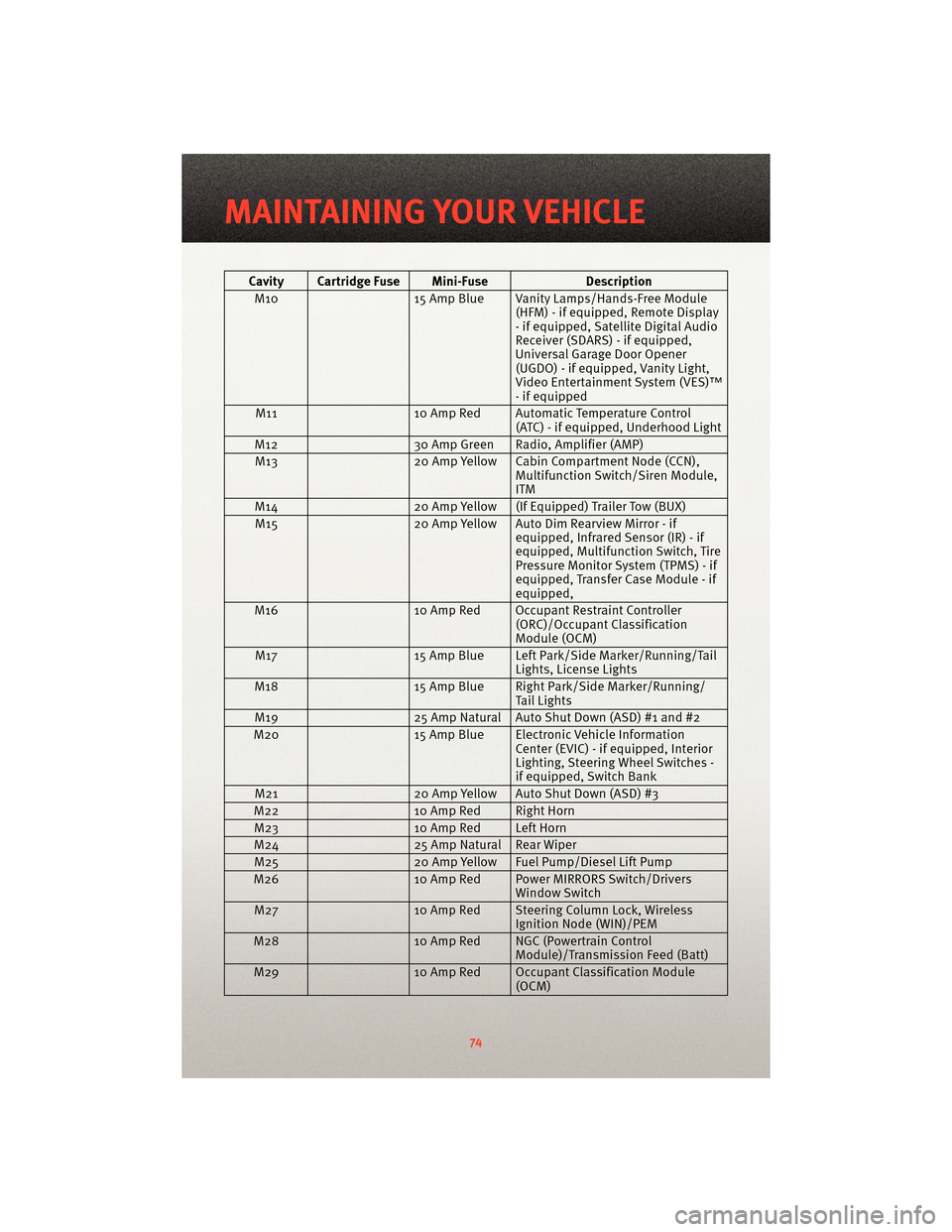
Cavity Cartridge Fuse Mini-FuseDescription
M10 15 Amp Blue Vanity Lamps/Hands-Free Module
(HFM) - if equipped, Remote Display
- if equipped, Satellite Digital Audio
Receiver (SDARS) - if equipped,
Universal Garage Door Opener
(UGDO) - if equipped, Vanity Light,
Video Entertainment System (VES)™
- if equipped
M11 10 Amp Red Automatic Temperature Control
(ATC) - if equipped, Underhood Light
M12 30 Amp Green Radio, Amplifier (AMP)
M13 20 Amp Yellow Cabin Compartment Node (CCN),
Multifunction Switch/Siren Module,
ITM
M14 20 Amp Yellow (If Equipped) Trailer Tow (BUX)
M15 20 Amp Yellow Auto Dim Rearview Mirror - if
equipped, Infrared Sensor (IR) - if
equipped, Multifunction Switch, Tire
Pressure Monitor System (TPMS) - if
equipped, Transfer Case Module - if
equipped,
M16 10 Amp Red Occupant Restraint Controller
(ORC)/OccupantClassification
Module (OCM)
M17 15 Amp Blue Left Park/Side Marker/Running/Tail
Lights, License Lights
M18 15 Amp Blue Right Park/Side Marker/Running/
Tail Lights
M19 25 Amp Natural Auto Shut Down (ASD) #1 and #2
M20 15 Amp Blue Electronic Vehicle Information
Center (EVIC) - if equipped, Interior
Lighting, Steering Wheel Switches -
if equipped, Switch Bank
M21 20 Amp Yellow Auto Shut Down (ASD) #3
M22 10 Amp Red Right Horn
M23 10 Amp Red Left Horn
M24 25 Amp Natural Rear Wiper
M25 20 Amp Yellow Fuel Pump/Diesel Lift Pump
M26 10 Amp Red Power MIRRORS Switch/Drivers
Window Switch
M27 10 Amp Red Steering Column Lock, Wireless
Ignition Node (WIN)/PEM
M28 10 Amp Red NGC (Powertrain Control
Module)/Transmission Feed (Batt)
M29 10 Amp Red Occupant Classification Module
(OCM)
MAINTAINING YOUR VEHICLE
74