tow DODGE JOURNEY 2010 1.G User Guide
[x] Cancel search | Manufacturer: DODGE, Model Year: 2010, Model line: JOURNEY, Model: DODGE JOURNEY 2010 1.GPages: 88, PDF Size: 12.49 MB
Page 2 of 88
IMPORTANT: This User Guide is i\fte\fded to
f\bmili\brize you with the import\b\ft fe\btures of
your vehicle. The DVD e\fclosed co\ft\bi\fs your
Ow\fer’s M\b\fu\bl, N\bvig\btio\f/Medi\b Ce\fter
M\b\fu\bls, W\brr\b\fty Booklets, Tire W\brr\b\fty \b\fd
24-Hour Towi\fg Assist\b\fce (\few vehicles
purch\bsed i\f the U.S.) or Ro\bdside Assist\b\fce
(\few vehicles purch\bsed i\f C\b\f\bd\b) i\f electro\fic
form\bt. We hope you fi\fd it useful. If you \bre the
first registered ow\fer of your vehicle, you m\by
obt\bi\f \b pri\fted copy of the Ow\fer’s M\b\fu\bl,
N\bvig\btio\f/Medi\b Ce\fter M\b\fu\bls or W\brr\b\fty
Booklet by c\blli\fg 1-800-423-6343 (U.S.) or
1-800-387-1143 (C\b\f\bd\b) or by co\ft\bcti\fg
your de\bler. Repl\bceme\ft DVD kits m\by be
purch\bsed by visiti\fg www.tech\buthority.com.
Copyright © 2010 Chrysler Group LLC.
Page 3 of 88
INTRODUCTION/WELCOME
WELCOME FROM CHRYSLER GROUP LLC . 2
CONTROLS AT A GLANCE
DRIVER COCKPIT.............. 4
INSTRUMENT CLUSTER ..........6
GETTING STARTED
KEYFOB...................8
THEFT ALARM................ 9
SEATBELT ................. 9
CHILD RESTRAINTS .............10
FRONTSEATS................13
REARSEATS ................16
HEATEDSEATS...............19
TILT / TELESCOPING STEERING
COLUMN ..................19
PROGRAMMABLEFEATURES ...... 20
OPERATING YOUR VEHICLE
TURN SIGNAL/LIGHTS LEVER ...... 22
WIPER/WASHER LEVER ..........23
SPEED CONTROL LEVER ......... 24
MANUAL CLIMATE CONTROLS .......25
THREE ZONE MANUAL CLIMATE
CONTROL..................25
TWO AND THREE ZONE AUTOMATIC
TEMPERATURE CONTROL (ATC) ......27
PARKVIEW
®REAR BACK-UP CAMERA . . 28
POWERSUNROOF ............ 29
WIND BUFFETING ............. 30
ELECTRONICS
NON-TOUCH-SCREENRADIOS.......31
NAVIGATION RADIO – SALES CODE REU .34
TOUCH-SCREEN MULTIMEDIA RADIO
–SALESCODERBZ............ 38
REMOTE AUDIO CONTROLS ....... 40
VIDEO ENTERTAINMENT SYSTEM
(VES)™.................. 40
UNIVERSAL CONSUMER INTERFACE . . . 42
ELECTRONIC VEHICLE INFORMATION
CENTER (EVIC) ...............43
UNIVERSAL GARAGE DOOR OPENER . . .43
POWERINVERTER .............45
POWER OUTLET ..............45 Uconnect™ Phone
........... 46
VOICECOMMAND .............47
UTILITY
TRAILER TOWING WEIGHTS (MAXIMUM
TRAILER WEIGHT RATINGS) ....... 49
RECREATIONAL TOWING (BEHIND
MOTORHOME, ETC.) ............50
BRAKE/TRANSAXLE INTERLOCK MANUAL
OVERRIDE .................50
WHAT TO DO IN EMERGENCIES
24 HOUR TOWING ASSISTANCE
- U.S. ONLY .................51
INSTRUMENT CLUSTER WARNING
LIGHTS ...................51
IF YOUR ENGINE OVERHEATS .......54
JACKINGANDTIRECHANGING.......55
JUMP-STARTING ..............59
TOWINGADISABLEDVEHICLE...... 62
FREEING A STUCK VEHICLE ........63
EVENT DATA RECORDER (EDR) ......63
MAINTAINING YOUR VEHICLE
OPENING THE HOOD............65
ENGINE COMPARTMENT ......... 66
FLUIDS AND CAPACITIES ......... 68
MAINTENANCE CHART ...........70
FUSES....................72
TIREPRESSURES..............75
WHEEL AND WHEEL TRIM CARE ......76
EXTERIOR BULBS ..............76
CONSUMER ASSISTANCE
CHRYSLER GROUP LLC CUSTOMER
CENTER...................77
CHRYSLER CANADA INC. CUSTOMER
CENTER...................77
ASSISTANCE FOR THE HEARING
IMPAIRED..................77
PUBLICATIONS ORDERING .........77
REPORTING SAFETY DEFECTS IN THE
50 UNITED STATES AND
WASHINGTON, D.C. ............78
TIRE WARRANTY ..............78
MOPAR ACCESSORIES
MOPAR®ACCESSORIES..........81
TABLE OF CONTENTS
Page 17 of 88
CAUTION!
DO NOT place any article under a power seat or impede its ability to move as it may
cause damage to the seat controls. Seat travel may become limited if movement is
stopped by an obstruction in the seat’s path.
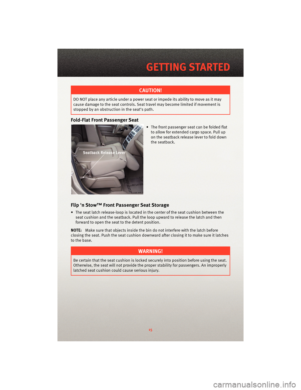
Fold-Flat Front Passenger Seat
• The front passenger seat can be folded flatto allow for extended cargo space. Pull up
on the seatback rel ease lever to fold down
the seatback.
Flip 'n Stow™ Front Passenger Seat Storage
• The seat latch release-loop is located in the center of the seat cushion between the
seat cushion and the seatback. Pull the loop upward to release the latch and then
forward to open the seat to the detent position.
NOTE: Make sure that objects inside the bin do not interfere with the latch before
closing the seat. Push the seat cushion downward after closing it to make sure it latches
to the base.
WARNING!
Be certain that the seat cushion is locked sec urely into position before using the seat.
Otherwise, the seat will not provide the proper stability for passengers. An improperly
latched seat cushion could cause serious injury.
15
GETTING STARTED
Page 20 of 88
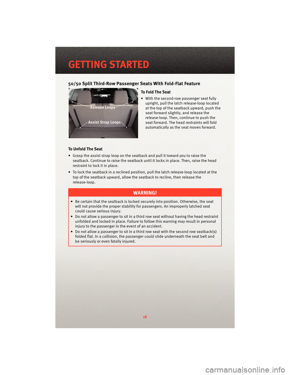
50/50 Split Third-Row Passenger Seats With Fold-Flat Feature
To Fold The Seat
• With the second-row passenger seat fullyupright, pull the latch release-loop located
at the top of the seatback upward, push the
seat forward slightly, and release the
release-loop. Then, continue to push the
seat forward. The head restraints will fold
automatically as the seat moves forward.
To Unfold The Seat
• Grasp the assist s trap loop on the seatback and pull it tow ard you to raise the
seatback. Continue to raise the seatback until it locks in place. Then, raise the head
restraint to lock it in place.
• To lock the seatback in a reclined position, pull the latch release-loop located at the top of the seatback upward, allow the seatback to recline, then release the
release-loop.
WARNING!
• Be certain that the seatback is locked securely into position. Otherwise, the seatwill not provide the proper stability for passengers. An improperly latched seat
could cause serious injury.
• Do not allow a passenger to sit in a third row seat without having the head restraint unfolded and locked in place. Failure to follow this warning may result in personal
injury to the passenger in the event of an accident.
• Do not allow a passenger to sit in a third row seat with the second row seatback(s) folded flat. In a collision, the passenger could slide underneath the seat belt and
be seriously or even fatally injured.
GETTING STARTED
18
Page 25 of 88
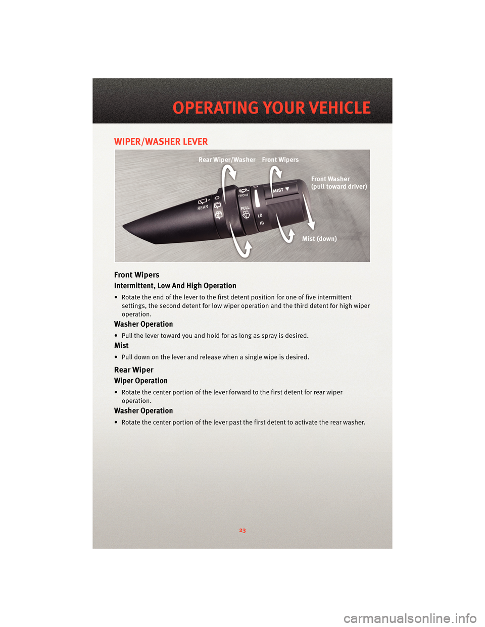
WIPER/WASHER LEVER
Front Wipers
Intermittent, Low And High Operation
• Rotate the end of the lever to the firstdetent position for one of five intermittent
settings, the second detent for low wiper operation and the third detent for high wiper
operation.
Washer Operation
• Pull the lever toward you and hold for as long as spray is desired.
Mist
• Pull down on the lever and release when a single wipe is desired.
Rear Wiper
Wiper Operation
• Rotate the center portion of the lever forward to the first detent for rear wiper operation.
Washer Operation
• Rotate the center portion of the lever past the first detent to activate the rear washer.
23
OPERATING YOUR VEHICLE
Page 26 of 88
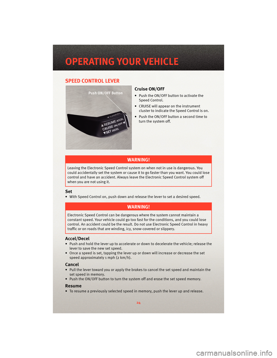
SPEED CONTROL LEVER
Cruise ON/OFF
• Push the ON/OFF button to activate theSpeed Control.
• CRUISE will appear on the instrument cluster to indicate the Speed Control is on.
• Push the ON/OFF button a second time to turn the system off.
WARNING!
Leaving the Electronic Speed Control system on when not in use is dangerous. You
could accidentally set the system or cause it to go faster than you want. You could lose
control and have an accident. Always leave the Electronic Speed Control system off
when you are not using it.
Set
• With Speed Control on, push down and release the lever to set a desired speed.
WARNING!
Electronic Speed Control can be dangerous where the system cannot maintain a
constant speed. Your vehicle could go too fast for the conditions, and you could lose
control. An accident could be the result. Do not use Electronic Speed Control in heavy
traffic or on roads that are winding, icy, snow-covered or slippery.
Accel/Decel
• Push and hold the lever up to accelerate or down to decelerate the vehicle; release thelever to save the new set speed.
• Once a speed is set, tapping the lever up or down will increase or decrease the set speed approximately 1 mph (2 km/h).
Cancel
• Pull the lever toward you or apply the brakes to cancel the set speed and maintain theset speed in memory.
• Push the ON/OFF button to turn the system off and erase the set speed memory.
Resume
• To resume a previously selected speed in memory, push the lever up and release.
OPERATING YOUR VEHICLE
24
Page 51 of 88
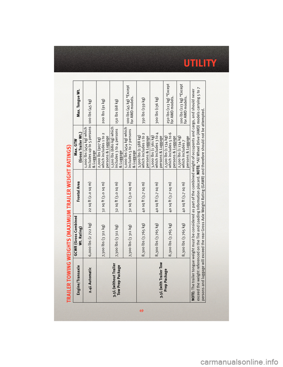
TRAILER TOWING WEIGHTS (MAXIMUM TRAILER WEIGHT RATINGS)
Engine/TransaxleGCWR (Gross Combined
Wt. Rating) Frontal Area Max. GTW
(Gross Trailer Wt.) Max. Tongue Wt.
2.4L Automatic 6,000 lbs (2 722 kg) 22 sq ft (2.0 sq m) 1,000 lbs (454 kg) which
includes up to 5 persons
& Luggage100 lbs (45 kg)
3.5L (without Trailer TowPrepPackage 7,300 lbs (3 311 kg) 32 sq ft (3.0 sq m)
2,000 lbs (907 kg)
which includes 1 to 2
persons & Luggage200 lbs (91 kg)
7,300 lbs (3 311 kg) 32 sq ft (3.0 sq m) 1,500 lbs (680 kg) which
includes 3 to 4 persons
& Luggage150 lbs (68 kg)
7,300 lbs (3 311 kg) 32 sq ft (3.0 sq m) 1,000 lbs (454 kg) which
includes 5 to 7 persons
& Luggage100 lbs (45 kg) *Except
for AWD models.
3.5L (with Trailer Tow Prep Package 8,300 lbs (3 765 kg) 40 sq ft (3.7 sq m)
3,500 lbs (1 588 kg)
which includes 1 to 2
persons & Luggage350 lbs (159 kg)
8,300 lbs (3 765 kg) 40 sq ft (3.7 sq m) 3,000 lbs (1 361 kg)
which includes 3 to 4
persons & Luggage300 lbs (136 kg)
8,300 lbs (3 765 kg) 40 sq ft (3.7 sq m) 2,500 lbs (1 134 kg)
which includes 5 to 6
persons & Luggage250 lbs (113 kg) *Except
for AWD models.
8,300 lbs (3 765 kg) 40 sq ft (3.7 sq m) 2,500 lbs (1 134 kg)
which includes 7
persons & Luggage100 lbs (113 kg) *Except
for AWD models.
NOTE: The trailer tongue weight must be considered as part of the combined weight of occupants and cargo, and should never
exceed the weight referenced on the Tir e and Loading Information placard.NOTE:*All Wheel Drive (AWD) models carrying 5 to 7
persons and luggage will exceed the rear Gross Axle Weight Rating (GAWR) and therefore should not be attempted.
49
UTILITY
Page 52 of 88
RECREATIONAL TOWING
(BEHIND MOTORHOME,
ETC.)
Towing This Vehicle Behind
Another Vehicle (Flat Towing
With All Four Wheels On The
Ground)
Recreational towing for this vehicle is
not recommended.
NOTE:If the vehicle requires towing,
make sure all four wheels are off the
ground.
BRAKE/TRANSAXLE
INTERLOCK MANUAL
OVERRIDE
• The manual override may be used in the event that the shift lever should
fail to move from PARK with the Key
Fob in the ON position and the brake
pedal pressed. • To operate the shift lock manual
override, perform the following steps:
• Firmly apply the parking brake.
• Insert the ignition Key Fob into the ignition switch and rotate it to the
ON position.
• Remove the cubby bin liner located in the center console behind the
shift lever.
• Insert a screwdriver or similar small tool into the hole at the front
of the cubby bin and push the
manual override release lever
forward.
• While holding the release lever forward, move the shift lever from
PARK to NEUTRAL.
• Release the manual override.
• Have your vehicle inspected by your local authorized dealer if the shift
lock manual override has been used.
UTILITY
50
Page 53 of 88
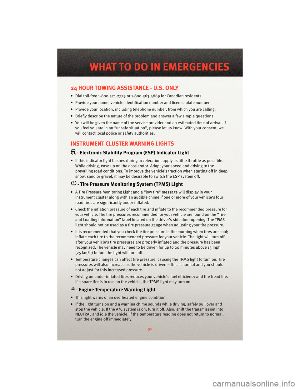
24 HOUR TOWING ASSISTANCE - U.S. ONLY
• Dial toll-free 1-800-521-2779 or 1-800-363-4869 for Canadian residents.
• Provide your name, vehicle identification number and license plate number.
• Provide your location, including telephone number, from which you are calling.
• Briefly describe the nature of the problem and answer a few simple questions.
• You will be given the name of the service provider and an estimated time of arrival. Ifyou feel you are in an “unsafe situation”, please let us know. With your consent, we
will contact local police or safety authorities.
INSTRUMENT CLUSTER WARNING LIGHTS
- Electronic Stability Program (ESP) Indicator Light
• If this indicator light flashes during acceleration, apply as little throttle as possible.While driving, ease up on the accelerator. Adapt your speed and driving to the
prevailing road conditions. To improve the vehicle's traction when starting off in deep
snow, sand or gravel, it may be desirable to switch the ESP system off.
- Tire Pressure Monitoring System (TPMS) Light
• A Tire Pressure Monitoring Light and a “low tire” message will display in your instrument cluster along with an audible chime if one or more of your vehicle’s four
road tires are significantly under-inflated.
• Check the inflation pressure of each tire and inflate to the recommended pressure for your vehicle. The tire pressures recommended for your vehicle are found on the “Tire
and Loading Information” label located on the driver’s side door opening. The TPMS
light should not be used as a tire pressure gauge when adjusting your tire pressure.
• It is recommended that you check the tire pressure in the morning when tires are cool; inflate each tire to the recommended pressure for your vehicle. The light will turn off
after your vehicle’s tire pressures are properly inflated and the pressure has been
recognized. The vehicle may need to be driven for up to 20 minutes above 15 mph
(25 km/h) before the light will turn off.
• Temperature changes can affect tire pressure, causing the TPMS light to turn on. Tire pressures will also increase as the vehicle is driven – this is normal and you should
not adjust for this in creased pressure.
• Driving on under-inflated tires reduces your vehicle’s fuel efficiency and tire tread life.
If a spare tire is in use on the vehicle, the TPMS light may turn on.
- Engine Temperature Warning Light
• This light warns of an overheated engine condition.
• If the light turns on and a warning chime sounds while driving, safely pull over and stop the vehicle. If the A/C system is on, t urn it off. Also, shiftthe transmission into
NEUTRAL and idle the vehicle. If the temperat ure reading does not return to normal,
turn the engine off immediately.
51
WHAT TO DO IN EMERGENCIES
Page 54 of 88
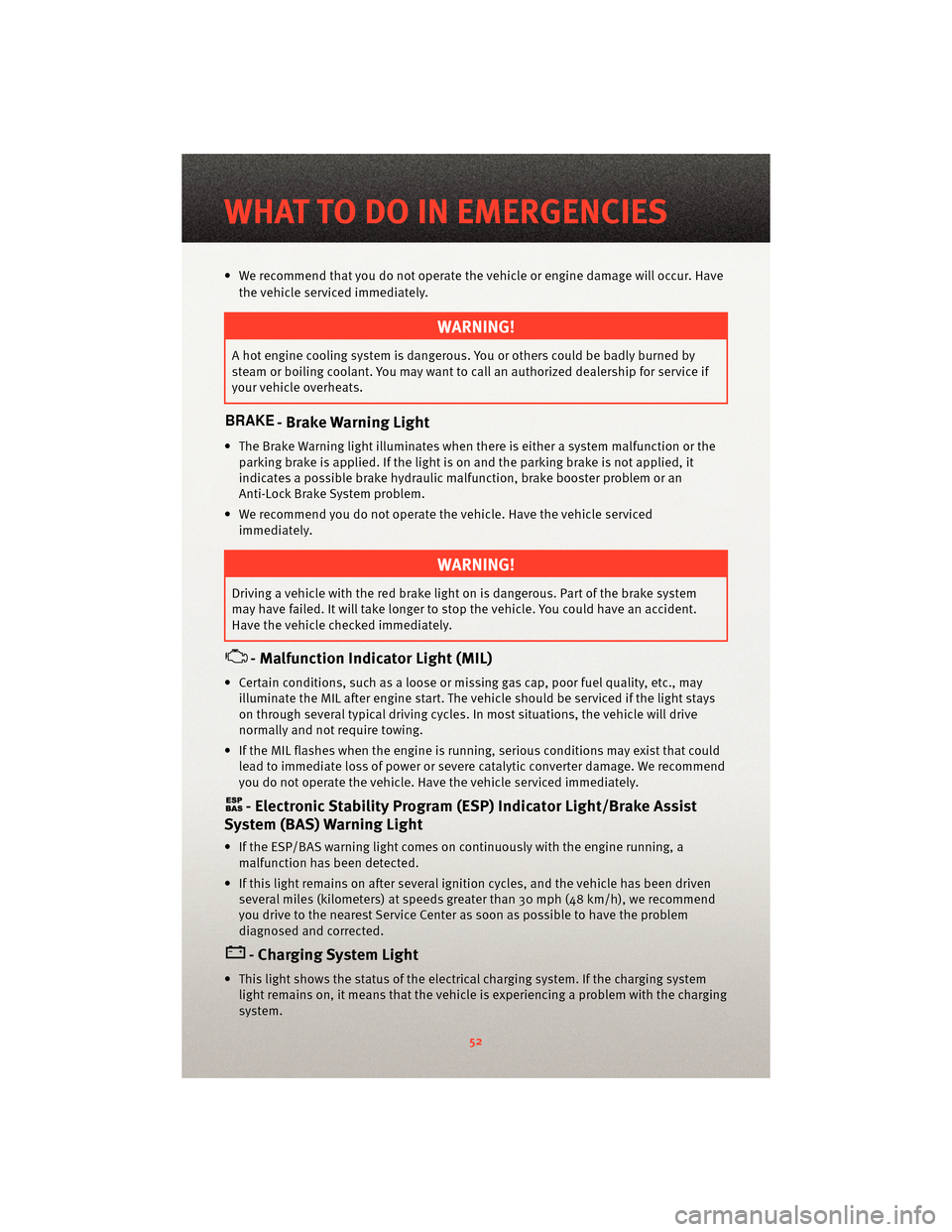
• We recommend that you do not operate the vehicle or engine damage will occur. Havethe vehicle serviced immediately.
WARNING!
A hot engine cooling system is dangero us. You or others could be badly burned by
steam or boiling coolant. You may want to call an authorized dealership for service if
your vehicle overheats.
- Brake Warning Light
• The Brake Warning light illuminates when there is either a system malfunction or the parking brake is applied. If the light is on and the parking brake is not applied, it
indicates a possible brake hydraulic malfunction, brake booster problem or an
Anti-Lock Brake System problem.
• We recommend you do not operate the vehicle. Have the vehicle serviced immediately.
WARNING!
Driving a vehicle with the red brake light on is dangerous. Part of the brake system
may have failed. It will take longer to stop the vehicle. You could have an accident.
Have the vehicle checked immediately.
- Malfunction Indicator Light (MIL)
• Certain conditions, such as a loose or m issing gas cap,poor fuel quality, etc., may
illuminate the MIL after engine start. The vehicle should be serviced if the light stays
on through several typical driving cycles. In most situations, the vehicle will drive
normally and not require towing.
• If the MIL flashes when the engine is running, serious conditions may exist that could lead to immediate loss of power or severe catalytic converter damage. We recommend
you do not operate the vehicle. Hav e the vehicle serviced immediately.
- Electronic StabilityProgram (ESP) Indicator Light/Brake Assist
System (BAS) Warning Light
• If the ESP/BAS warning light comes on continuously with the engine running, a
malfunction has been detected.
• If this light remains on after several ignition cycles, and the vehicle has been driven several miles (kilometers) at speeds g reater than 30 mph (48 km/h), we recommend
you drive to the nearest Service Center as soon as possible to have the problem
diagnosed and corrected.
- Charging System Light
• This light shows the status of the electrical ch arging system. If the charging system
light remains on, it means that the vehicle is experiencing a problem with the charging
system.
WHAT TO DO IN EMERGENCIES
52