ECU DODGE JOURNEY 2011 1.G User Guide
[x] Cancel search | Manufacturer: DODGE, Model Year: 2011, Model line: JOURNEY, Model: DODGE JOURNEY 2011 1.GPages: 108, PDF Size: 4.41 MB
Page 9 of 108
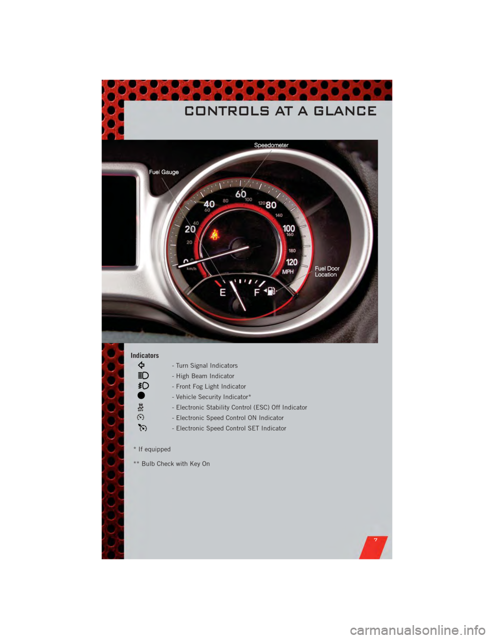
Indicators
- Turn Signal Indicators
- High Beam Indicator
- Front Fog Light Indicator
- Vehicle Security Indicator*
- Electronic Stability Control (ESC) Off Indicator
- Electronic Speed Control ON Indicator
- Electronic Speed Control SET Indicator
* If equipped
** Bulb Check with Key On
CONTROLS AT A GLANCE
7
Page 11 of 108
• The vehicle must be cycled to the ON/RUN position after two consecutivetimeouts.
WARNING!
• Do not start or run an engine in a closed garage or confined area. Exhaust gascontains Carbon Monoxide (CO) which is odorless and colorless. Carbon
Monoxide is poisonous and can cause you or others to be severely injured or
killed when inhaled.
• Keep Key Fob transmitters away from children. Operation of the Remote Start System, windows, door locks or other controls could cause you and others to
be severely injured or killed.
KEYLESS ENTER-N-GO
• The Keyless Enter-N-Go system is an enhancement to the vehicle's Key Fob. This
feature allows you to lock and unlock the vehicle's door(s) and liftgate without
having to press the Key Fob lock or unlock buttons, as well as starting and
stopping the vehicle with the press of a button.
To Unlock From The Driver or Passenger Side:
• With a valid Keyless Enter-N-Go Key Fob located outside the vehicle and within5 ft (1.5m) of the driver or passenger side door handle, grab either front door
handle to unlock the door automatically.
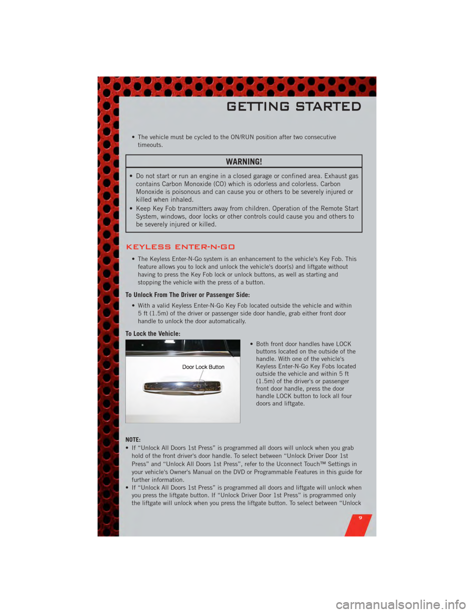
To Lock the Vehicle:
• Both front door handles have LOCKbuttons located on the outside of the
handle. With one of the vehicle's
Keyless Enter-N-Go Key Fobs located
outside the vehicle and within 5 ft
(1.5m) of the driver's or passenger
front door handle, press the door
handle LOCK button to lock all four
doors and liftgate.
NOTE:
• If “Unlock All Doors 1st Press” is programmed all doors will unlock when you grab hold of the front driver's door handle. To select between “Unlock Driver Door 1st
Press” and “Unlock All Doors 1st Press”, refer to the Uconnect Touch™ Settings in
your vehicle's Owner's Manual on the DVD or Programmable Features in this guide for
further information.
• If “Unlock All Doors 1st Press” is programmed all doors and liftgate will unlock when you press the liftgate button. If “Unlock Driver Door 1st Press” is programmed only
the liftgate will unlock when you press the liftgate button. To select between “Unlock
GETTING STARTED
9
Page 16 of 108
CHILD RESTRAINTS
• Children 12 years and under should ride properly buckled up in a rear seat, ifavailable. According to crash statistics, children are safer when properly restrained
in the rear seats rather than in the front.
• Every state in the United States and all Canadian provinces require that small children ride in proper restraint systems. This is the law, and you can be
prosecuted for ignoring it.
Integrated Child Booster Seat
• The Integrated Child Booster Seat is located in each outboard second-rowpassenger seat, is designed for children weighing between 48 and 85 lbs (22 and
39 kg) and between 47 in (119 cm) and 57 in (145 cm) tall.
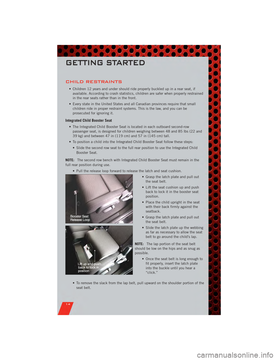
• To position a child into the Integrated Child Booster Seat follow these steps: • Slide the second row seat to the full rear position to use the Integrated ChildBooster Seat.
NOTE: The second row bench with Integrated Child Booster Seat must remain in the
full rear position during use.
• Pull the release loop forward to release the latch and seat cushion. • Grasp the latch plate and pull outthe seat belt.
• Lift the seat cushion up and push back to lock it in the booster seat
position.
• Place the child upright in the seat with their back firmly against the
seatback.
• Grasp the latch plate and pull out the seat belt.
• Slide the latch plate up the webbing as far as necessary to allow the seat
belt to go around the child’s lap.
NOTE: The lap portion of the seat belt
should be low on the hips and as snug as
possible.
• Once the seat belt is long enough tofit properly, insert the latch plate
into the buckle until you hear a
“click.”
• To remove the slack from the lap belt, pull upward on the shoulder portion of the seat belt.
GETTING STARTED
14
Page 18 of 108
Installing The Child Restraint Using The Vehicle Seat Belts
• To install a child restraint, first, pull enough of the seat belt webbing from theretractor to route it through the belt path of the child restraint and slide the latch
plate into the buckle.
• Next, extract all the seat belt webbing out of the retractor and then allow the belt to retract into the retractor. Finally, pull on any excess webbing to tighten the lap
portion around the child restraint. Any seat belt system will loosen with time, so
check the belt occasionally, and pull it tight if necessary.
• Route the tether strap to provide the most direct path for the strap between the anchor and the child seat, preferably between the head restraint posts underneath
the head restraint.
• Attach the tether strap hook of the child restraint to the tether anchor and remove slack in the tether strap according to the child restraint manufacturer's
instructions.
NOTE: Ensure that the tether strap does not slip into the opening between the
seatbacks as you remove slack in the strap.
WARNING!
• In a collision, an unrestrained child, even a tiny baby, can become a projectile inside the vehicle. The force required to hold even an infant on
your lap could become so great that you could not hold the child, no matter
how strong you are. The child and others could be severely injured or killed.
Any child riding in your vehicle should be in a proper restraint for the child's
size.
• Rearward-facing child seats must never be used in the front seat of a vehicle with a front passenger air bag. An air bag deployment could cause severe
injury or death to infants in this position.
• Improper installation of a child restraint to the LATCH anchorages can lead to failure of an infant or child restraint. The child could be severely injured or
killed. Follow the manufacturer’s directions exactly when installing an infant
or child restraint.
• An incorrectly anchored tether strap could lead to increased head motion and possible injury to the child. Use only the anchor positions directly behind the
child seat to secure a child restraint top tether strap.
GETTING STARTED
16
Page 21 of 108
WARNING!(Continued)
• Be certain that the seat cushion is locked securely into position before usingthe seat. Otherwise, the seat will not provide the proper stability for
passengers. An improperly latched seat cushion could cause serious injury.
REAR SEATS
60/40 Split Second-Row Passenger Seats
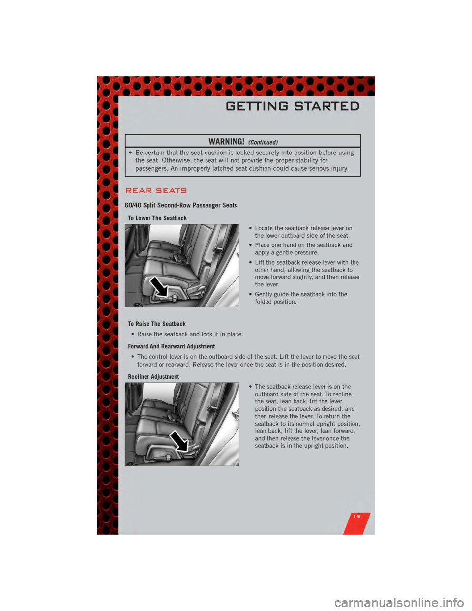
To Lower The Seatback
• Locate the seatback release lever onthe lower outboard side of the seat.
• Place one hand on the seatback and apply a gentle pressure.
• Lift the seatback release lever with the other hand, allowing the seatback to
move forward slightly, and then release
the lever.
• Gently guide the seatback into the folded position.
To Raise The Seatback • Raise the seatback and lock it in place.
Forward And Rearward Adjustment • The control lever is on the outboard side of the seat. Lift the lever to move the seat forward or rearward. Release the lever once the seat is in the position desired.
Recliner Adjustment • The seatback release lever is on theoutboard side of the seat. To recline
the seat, lean back, lift the lever,
position the seatback as desired, and
then release the lever. To return the
seatback to its normal upright position,
lean back, lift the lever, lean forward,
and then release the lever once the
seatback is in the upright position.
GETTING STARTED
19
Page 23 of 108
WARNING!
• Be certain that the seatback is locked securely into position. Otherwise, theseat will not provide the proper stability for child seats and/or passengers. An
improperly latched seat could cause you and others to be severely injured or
killed.
• Do not allow a passenger to sit in a third row seat without having the head restraint unfolded and locked in place or seatback(s) folded flat. Failure to
follow this warning may result in the passengers being severely injured or
killed in the event of a collision.
• Do not drive the vehicle with the seat in the Tip 'n Slide™ position, as it is only intended for entering and exiting the third row seats. Failure to follow
this warning may result in you and others being severely injured or killed.
• Be certain that the seatback and seat are locked securely into position. Otherwise, the seat will not provide the proper stability for child seats and/or
passengers. An improperly latched seat could cause you or others to be
severely injured or killed.
HEATED SEATS
Front Heated Seats
• The heated seats are operated using the Uconnect Touch™ System.
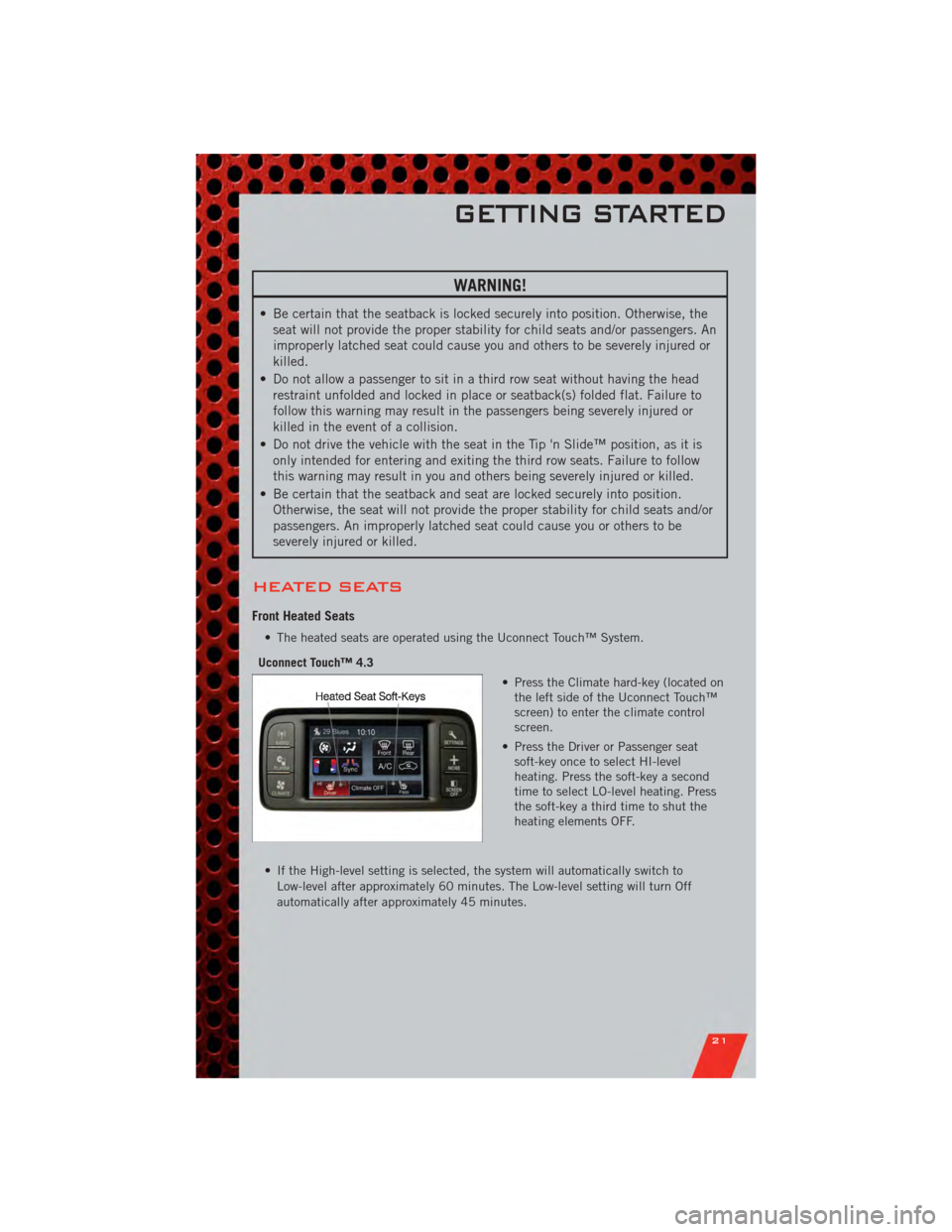
Uconnect Touch™ 4.3 • Press the Climate hard-key (located onthe left side of the Uconnect Touch™
screen) to enter the climate control
screen.
• Press the Driver or Passenger seat soft-key once to select HI-level
heating. Press the soft-key a second
time to select LO-level heating. Press
the soft-key a third time to shut the
heating elements OFF.
• If the High-level setting is selected, the system will automatically switch to Low-level after approximately 60 minutes. The Low-level setting will turn Off
automatically after approximately 45 minutes.
GETTING STARTED
21
Page 33 of 108
WARNING!
• Never leave children in a vehicle with the key in the ignition switch.Occupants, particularly unattended children, can become entrapped by the
power sunroof while operating the power sunroof switch. Such entrapment
may result in serious injury or death.
• In a collision, there is a greater risk of being thrown from a vehicle with an open sunroof. You could also be severely injured or killed. Always fasten your
seat belt properly and make sure all passengers are properly secured.
• Do not allow small children to operate the sunroof. Never allow your fingers, other body parts, or any object to project through the sunroof opening. Injury
may result.
WIND BUFFETING
• Wind buffeting can be described as a helicopter-type percussion sound. Ifbuffeting occurs with the rear windows open, adjust the front and rear windows
together.
• If buffeting occurs with the sunroof open, adjust the sunroof opening, or adjust any window. This will minimize buffeting.
OPERATING YOUR VEHICLE
31
Page 74 of 108
Jacking And Tire Changing Instructions
• Remove the spare tire, jack and tools from the stored location.
• Loosen (but do not remove) the wheel lug nuts by turning them counterclockwiseone turn while the wheel is still on the ground.
• Assemble the jack and jacking tools. Connect the jack handle driver to the extension, then to the lug wrench.
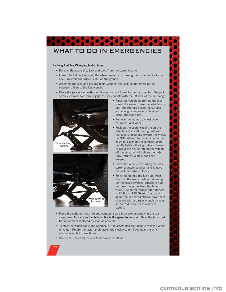
• Place the jack underneath the lift area that is closest to the flat tire. Turn the jack screw clockwise to firmly engage the jack saddle with the lift area of the sill flange.
• Raise the vehicle by turning the jackscrew clockwise. Raise the vehicle only
until the tire just clears the surface
and enough clearance is obtained to
install the spare tire.
• Remove the lug nuts, wheel cover (if equipped) and wheel.
• Position the spare wheel/tire on the vehicle and install the lug nuts with
the cone-shaped end toward the wheel.
Do NOT attempt to install a center cap
or wheel cover on the compact spare.
Lightly tighten the lug nuts clockwise.
To avoid the risk of forcing the vehicle
off the jack, do not tighten the nuts
fully until the vehicle has been
lowered.
• Lower the vehicle by turning the jack screw counterclockwise, and remove
the jack and wheel blocks.
• Finish tightening the lug nuts. Push down on the wrench while tightening
for increased leverage. Alternate nuts
until each one has been tightened
twice. The correct wheel nut tightness
is 95 ft lbs (130 N•m). If in doubt
about the correct tightness, have them
checked with a torque wrench by your
authorized dealer or at a service
station.
• Place the deflated (flat) tire and compact spare tire cover assembly in the rear cargo area. Do not stow the deflated tire in the spare tire location. Have the full-sized
tire repaired or replaced as soon as possible.
• To stow the winch cable and retainer, fit the assembled jack-handle over the winch drive nut. Rotate the jack-handle assembly clockwise until you hear the winch
mechanism click three times.
• Secure the jack and tools in their proper locations.
WHAT TO DO IN EMERGENCIES
72
Page 90 of 108
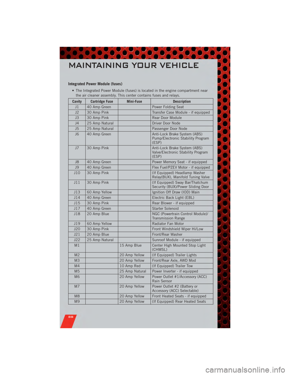
Integrated Power Module (fuses)
• The Integrated Power Module (fuses) is located in the engine compartment nearthe air cleaner assembly. This center contains fuses and relays.
Cavity Cartridge Fuse Mini-Fuse Description
J1 40 Amp Green Power Folding Seat
J2 30 Amp Pink Transfer Case Module - if equipped
J3 30 Amp Pink Rear Door Module
J4 25 Amp Natural Driver Door Node
J5 25 Amp Natural Passenger Door Node
J6 40 Amp Green Anti-Lock Brake System (ABS)
Pump/Electronic Stability Program
(ESP)
J7 30 Amp Pink Anti-Lock Brake System (ABS)
Valve/Electronic Stability Program
(ESP)
J8 40 Amp Green Power Memory Seat - if equipped
J9 40 Amp Green Flex Fuel/PZEV Motor - if equipped
J10 30 Amp Pink (If Equipped) Headlamp Washer
Relay(BUX), Manifold Tuning Valve
J11 30 Amp Pink (If Equipped) Sway Bar/Thatchum
Security (BUX)/Power Sliding Door
J13 60 Amp Yellow Ignition Off Draw (IOD) Main
J14 40 Amp Green Electric Back Light (EBL)
J15 30 Amp Pink Rear Blower - if equipped
J17 40 Amp Green Starter Solenoid
J18 20 Amp Blue NGC (Powertrain Control Module)/
Transmission Range
J19 60 Amp Yellow Radiator Fan Motor
J20 30 Amp Pink Front Windshield Wiper Hi/Low
J21 20 Amp Blue Front/Rear Washer
J22 25 Amp Natural Sunroof Module - if equipped
M1 15 Amp Blue Center High Mounted Stop Light
(CHMSL)
M2 20 Amp Yellow (If Equipped) Trailer Lights
M3 20 Amp Yellow Front/Rear Axle, AWD Mod
M4 10 Amp Red (If Equipped) Trailer Tow
M5 25 Amp Natural Power Inverter - if equipped
M6 20 Amp Yellow Power Outlet #1/Accessory (ACC)
Rain Sensor
M7 20 Amp Yellow Power Outlet #2 (Battery or
Accessory (ACC) Selectable)
M8 20 Amp Yellow Front Heated Seats - if equipped
M9 20 Amp Yellow (If Equipped) Rear Heated Seats
MAINTAINING YOUR VEHICLE
88
Page 95 of 108
REPORTING SAFETY
DEFECTS IN THE 50
UNITED STATES AND
WASHINGTON, D.C.
• If you believe that your vehicle has adefect that could cause a collision or
cause injury or death, you should
immediately inform the National
Highway Traffic Safety
Administration (NHTSA) in addition
to notifying the manufacturer.
• If NHTSA receives similar complaints, it may open an
investigation, and if it finds that a
safety defect exists in a group of
vehicles, it may order a recall and
remedy campaign. However, NHTSA
cannot become involved in individual
problems between you, your
authorized dealer, and the
manufacturer.
• To contact NHTSA, you may either call the Auto Safety Hotline toll free
at 1–888–327–4236 (TTY:
1–800–424– 9153), or go to
http://www.safercar.gov; or write to:
Administrator, NHTSA, 1200 New
Jersey Avenue, SE., West Building,
Washington, D.C. 20590. You can
also obtain other information about
motor vehicle safety from
http://www.safercar.gov.
In Canada
• If you believe that your vehicle has a
safety defect, you should contact the
Customer Service Department
immediately. Canadian customers
who wish to report a safety defect to
the Canadian government should
contact Transport Canada, Motor
Vehicle Defect Investigations and
Recalls at 1-800-333-0510 or go to
http://www.tc.gc.ca/roadsafety/
• French Canadian customers who wish to report a safety defect to the
Canadian government should contact
Transport Canada, Motor Vehicle
Defect Investigations and Recalls at
1-800-333-0510 or go to
http://www.tc.gc.ca/securiteroutiere/
CONSUMER ASSISTANCE
93