seats DODGE JOURNEY 2011 1.G User Guide
[x] Cancel search | Manufacturer: DODGE, Model Year: 2011, Model line: JOURNEY, Model: DODGE JOURNEY 2011 1.GPages: 108, PDF Size: 4.41 MB
Page 3 of 108
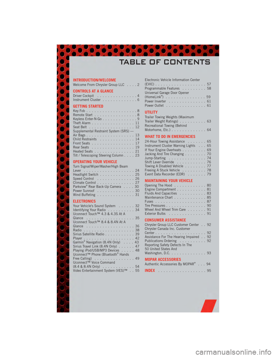
INTRODUCTION/WELCOMEWelcome From Chrysler Group LLC....2
CONTROLS AT A GLANCEDriver Cockpit...............4
Instrument Cluster .............6
GETTING STARTEDKeyFob...................8
Remote Start................8
Keyless Enter-N-Go .............9
Theft Alarm ................11
Seat Belt .................12
Supplemental Restraint System (SRS) —
Air Bags ..................13
Child Restraints .............14
Front Seats ................17
Rear Seats ................19
Heated Seats ...............21
Tilt / Telescoping Steering Column ....23
OPERATING YOUR VEHICLETurn Signal/Wiper/Washer/High Beam
Lever...................24
Headlight Switch .............25
Speed Control ..............26
Climate Control ..............27
Parkview
®Rear Back-Up Camera ....30
Power Sunroof ..............30
Wind Buffeting ..............31
ELECTRONICSYour Vehicle's Sound System ......32
Identifying Your Radio ..........34
Uconnect Touch™ 4.3 & 4.3S At A
Glance ..................35
Uconnect Touch™ 8.4 & 8.4N At A
Glance ..................36
Radio ...................38
Sirius Satellite Radio ...........39
Player ...................42
Garmin
®Navigation (8.4N Only) ....43
Sirius Travel Link (8.4N Only) ......47
Playing iPod/USB/MP3 Devices .....48
Uconnect™ Phone (Bluetooth
®Hands
Free Calling) ...............49
Uconnect™ Voice Command
(8.4 & 8.4N Only) ............54
Video Entertainment System (VES)™ . . 55 Electronic Vehicle Information Center
(EVIC)
...................57
Programmable Features .........58
Universal Garage Door Opener
(HomeLink
®) ...............59
Power Inverter ..............61
Power Outlet ...............61
UTILITY
Trailer Towing Weights (Maximum
Trailer Weight Ratings) ..........63
Recreational Towing (Behind
Motorhome, Etc.) .............64
WHAT TO DO IN EMERGENCIES
24-Hour Towing Assistance .......65
Instrument Cluster Warning Lights . . . 65
If Your Engine Overheats .........69
Jacking And Tire Changing ........70
Jump-Starting ..............74
Shift Lever Override ...........76
Towing A Disabled Vehicle ........77
Freeing A Stuck Vehicle .........78
Event Data Recorder (EDR) .......79
MAINTAINING YOUR VEHICLEOpening The Hood............80
Engine Compartment ...........81
Fluids And Capacities ..........83
Maintenance Chart ............85
Fuses ...................87
Tire Pressures ...............90
Wheel And Wheel Trim Care .......91
Exterior Bulbs ..............91
CONSUMER ASSISTANCEChrysler Group LLC Customer Center . . 92
Chrysler Canada Inc. Customer
Center...................92
Assistance For The Hearing Impaired . . 92
Publications Ordering ..........92
Reporting Safety Defects In The
50 United States And
Washington, D.C. .............93
MOPAR ACCESSORIESAuthentic Accessories By MOPAR®...94
INDEX..................95
TABLE OF CONTENTS
Page 16 of 108
CHILD RESTRAINTS
• Children 12 years and under should ride properly buckled up in a rear seat, ifavailable. According to crash statistics, children are safer when properly restrained
in the rear seats rather than in the front.
• Every state in the United States and all Canadian provinces require that small children ride in proper restraint systems. This is the law, and you can be
prosecuted for ignoring it.
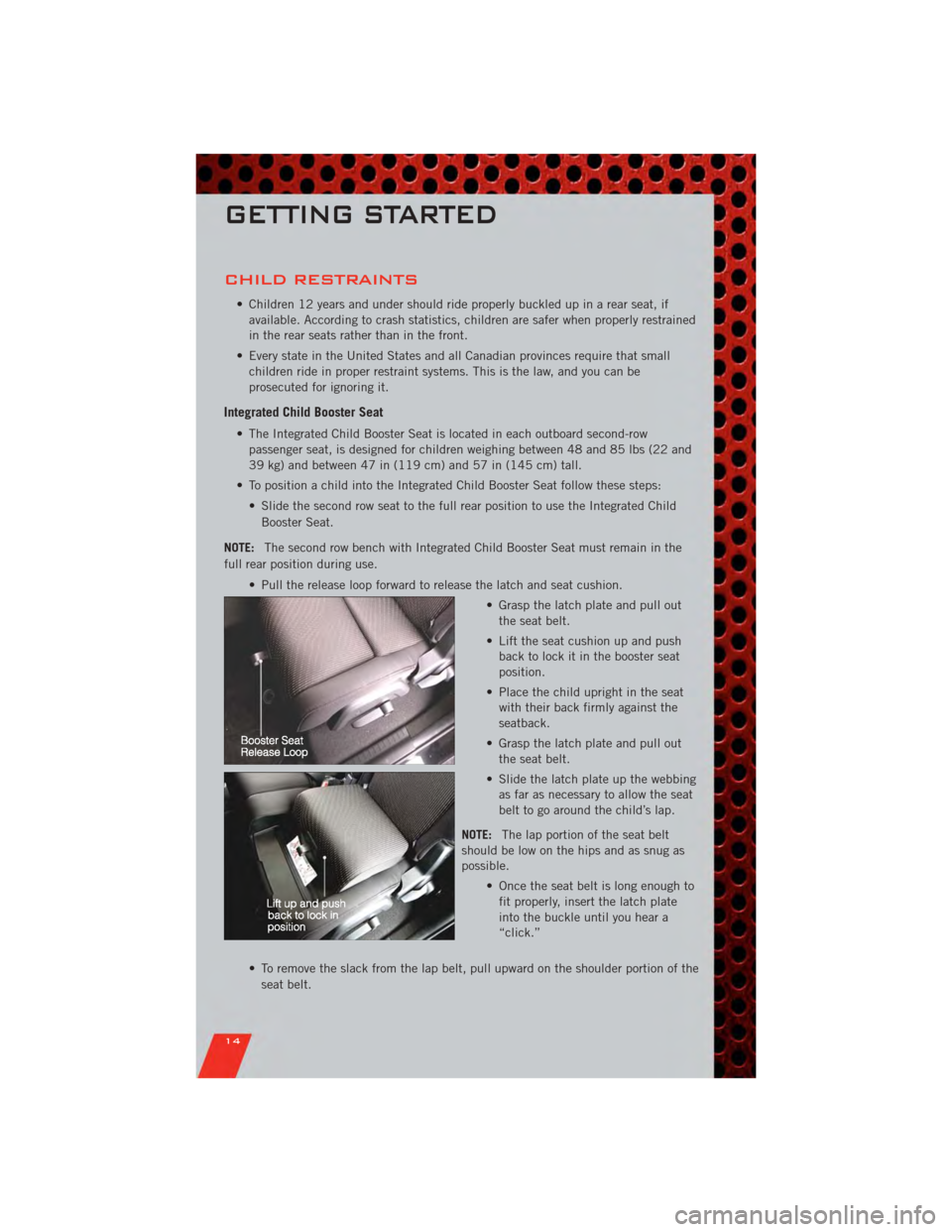
Integrated Child Booster Seat
• The Integrated Child Booster Seat is located in each outboard second-rowpassenger seat, is designed for children weighing between 48 and 85 lbs (22 and
39 kg) and between 47 in (119 cm) and 57 in (145 cm) tall.
• To position a child into the Integrated Child Booster Seat follow these steps: • Slide the second row seat to the full rear position to use the Integrated ChildBooster Seat.
NOTE: The second row bench with Integrated Child Booster Seat must remain in the
full rear position during use.
• Pull the release loop forward to release the latch and seat cushion. • Grasp the latch plate and pull outthe seat belt.
• Lift the seat cushion up and push back to lock it in the booster seat
position.
• Place the child upright in the seat with their back firmly against the
seatback.
• Grasp the latch plate and pull out the seat belt.
• Slide the latch plate up the webbing as far as necessary to allow the seat
belt to go around the child’s lap.
NOTE: The lap portion of the seat belt
should be low on the hips and as snug as
possible.
• Once the seat belt is long enough tofit properly, insert the latch plate
into the buckle until you hear a
“click.”
• To remove the slack from the lap belt, pull upward on the shoulder portion of the seat belt.
GETTING STARTED
14
Page 17 of 108
Installing The LATCH - Compatible Child Restraint System
• Your vehicle’s second row passenger seats are equipped with the child restraintanchorage system called LATCH, which stands for Lower Anchors and Tether for
CHildren.
• All three second-row passenger seating positions have lower anchors that are capable of accommodating LATCH-compatible child seats.
• Rigid fixed lower attachments can only be used in the outboard seating positions. Flexible lower attachments can be used in all seating positions.
• When installing a child seat in the center seating position use one lower anchorage from the outboard seating position and the center seat dedicated lower anchorage.
If two child seats are installed in adjacent seating positions you must use the
vehicle seat belt in the center seating position.
• You should NEVERinstall LATCH-compatible child seats so that two seats share a
common lower anchorage.
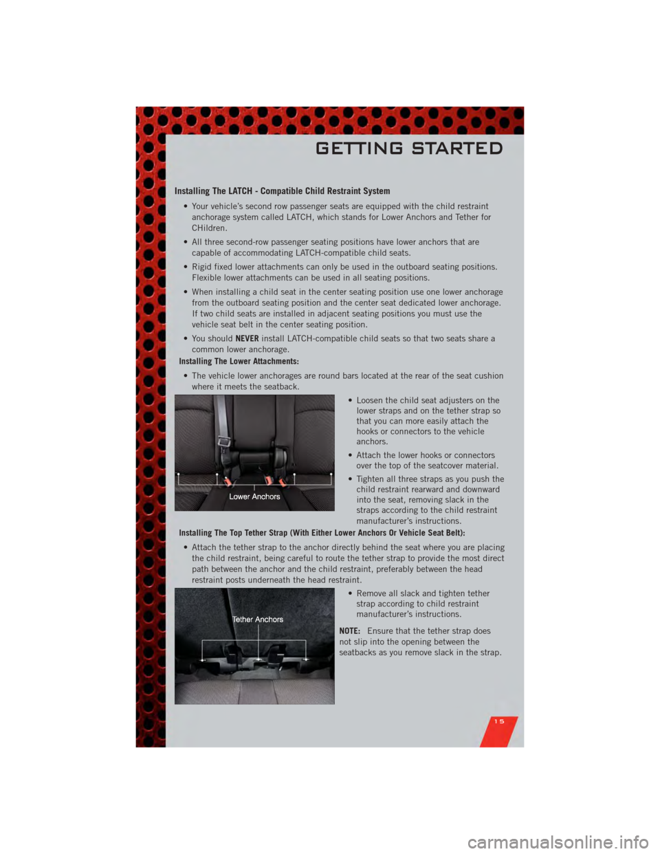
Installing The Lower Attachments:
• The vehicle lower anchorages are round bars located at the rear of the seat cushion where it meets the seatback.
• Loosen the child seat adjusters on thelower straps and on the tether strap so
that you can more easily attach the
hooks or connectors to the vehicle
anchors.
• Attach the lower hooks or connectors over the top of the seatcover material.
• Tighten all three straps as you push the child restraint rearward and downward
into the seat, removing slack in the
straps according to the child restraint
manufacturer’s instructions.
Installing The Top Tether Strap (With Either Lower Anchors Or Vehicle Seat Belt):
• Attach the tether strap to the anchor directly behind the seat where you are placing the child restraint, being careful to route the tether strap to provide the most direct
path between the anchor and the child restraint, preferably between the head
restraint posts underneath the head restraint.
• Remove all slack and tighten tetherstrap according to child restraint
manufacturer’s instructions.
NOTE: Ensure that the tether strap does
not slip into the opening between the
seatbacks as you remove slack in the strap.
GETTING STARTED
15
Page 18 of 108
Installing The Child Restraint Using The Vehicle Seat Belts
• To install a child restraint, first, pull enough of the seat belt webbing from theretractor to route it through the belt path of the child restraint and slide the latch
plate into the buckle.
• Next, extract all the seat belt webbing out of the retractor and then allow the belt to retract into the retractor. Finally, pull on any excess webbing to tighten the lap
portion around the child restraint. Any seat belt system will loosen with time, so
check the belt occasionally, and pull it tight if necessary.
• Route the tether strap to provide the most direct path for the strap between the anchor and the child seat, preferably between the head restraint posts underneath
the head restraint.
• Attach the tether strap hook of the child restraint to the tether anchor and remove slack in the tether strap according to the child restraint manufacturer's
instructions.
NOTE: Ensure that the tether strap does not slip into the opening between the
seatbacks as you remove slack in the strap.
WARNING!
• In a collision, an unrestrained child, even a tiny baby, can become a projectile inside the vehicle. The force required to hold even an infant on
your lap could become so great that you could not hold the child, no matter
how strong you are. The child and others could be severely injured or killed.
Any child riding in your vehicle should be in a proper restraint for the child's
size.
• Rearward-facing child seats must never be used in the front seat of a vehicle with a front passenger air bag. An air bag deployment could cause severe
injury or death to infants in this position.
• Improper installation of a child restraint to the LATCH anchorages can lead to failure of an infant or child restraint. The child could be severely injured or
killed. Follow the manufacturer’s directions exactly when installing an infant
or child restraint.
• An incorrectly anchored tether strap could lead to increased head motion and possible injury to the child. Use only the anchor positions directly behind the
child seat to secure a child restraint top tether strap.
GETTING STARTED
16
Page 19 of 108
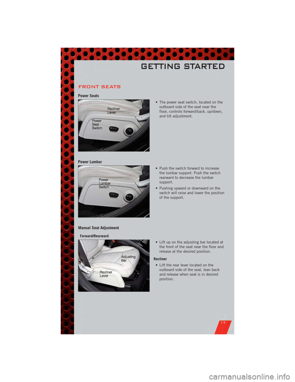
FRONT SEATS
Power Seats
• The power seat switch, located on theoutboard side of the seat near the
floor, controls forward/back, up/down,
and tilt adjustment.
Power Lumbar
• Push the switch forward to increasethe lumbar support. Push the switch
rearward to decrease the lumbar
support.
• Pushing upward or downward on the switch will raise and lower the position
of the support.
Manual Seat Adjustment
Forward/Rearward
• Lift up on the adjusting bar located atthe front of the seat near the floor and
release at the desired position.
Recliner • Lift the rear lever located on the outboard side of the seat, lean back
and release when seat is in desired
position.
GETTING STARTED
17
Page 21 of 108
WARNING!(Continued)
• Be certain that the seat cushion is locked securely into position before usingthe seat. Otherwise, the seat will not provide the proper stability for
passengers. An improperly latched seat cushion could cause serious injury.
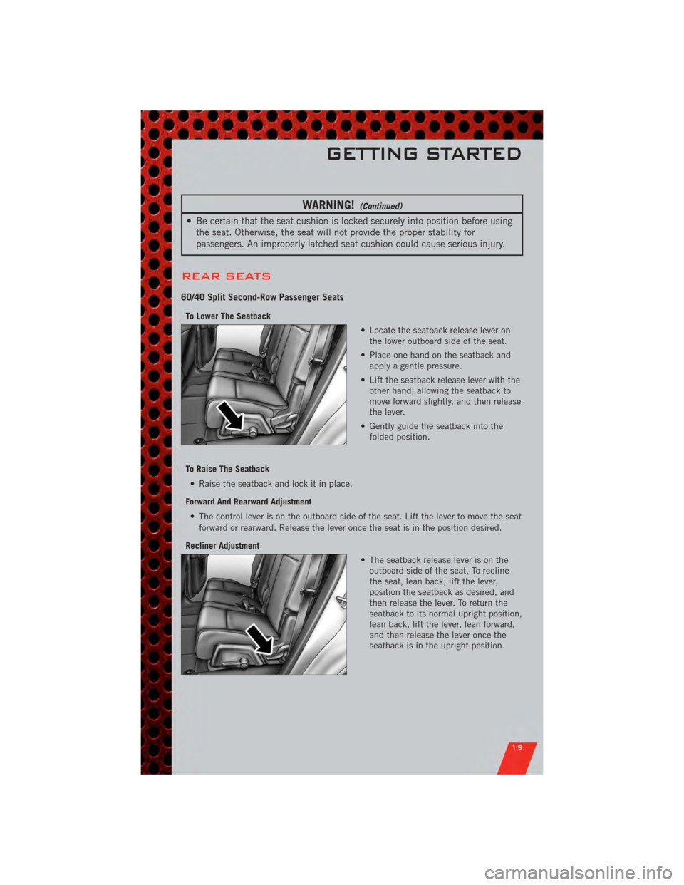
REAR SEATS
60/40 Split Second-Row Passenger Seats
To Lower The Seatback
• Locate the seatback release lever onthe lower outboard side of the seat.
• Place one hand on the seatback and apply a gentle pressure.
• Lift the seatback release lever with the other hand, allowing the seatback to
move forward slightly, and then release
the lever.
• Gently guide the seatback into the folded position.
To Raise The Seatback • Raise the seatback and lock it in place.
Forward And Rearward Adjustment • The control lever is on the outboard side of the seat. Lift the lever to move the seat forward or rearward. Release the lever once the seat is in the position desired.
Recliner Adjustment • The seatback release lever is on theoutboard side of the seat. To recline
the seat, lean back, lift the lever,
position the seatback as desired, and
then release the lever. To return the
seatback to its normal upright position,
lean back, lift the lever, lean forward,
and then release the lever once the
seatback is in the upright position.
GETTING STARTED
19
Page 22 of 108
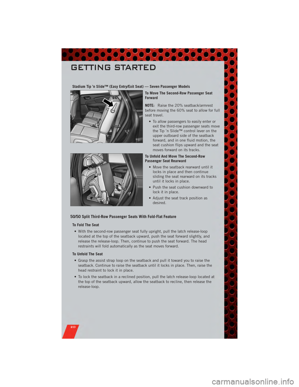
Stadium Tip ’n Slide™ (Easy Entry/Exit Seat) — Seven Passenger ModelsTo Move The Second-Row Passenger Seat
Forward
NOTE:Raise the 20% seatback/armrest
before moving the 60% seat to allow for full
seat travel.
• To allow passengers to easily enter orexit the third-row passenger seats move
the Tip ’n Slide™ control lever on the
upper outboard side of the seatback
forward, and in one fluid motion, the
seat cushion flips upward and the seat
moves forward on its tracks.
To Unfold And Move The Second-Row
Passenger Seat Rearward • Move the seatback rearward until itlocks in place and then continue
sliding the seat rearward on its tracks
until it locks in place.
• Push the seat cushion downward to lock it in place.
• Adjust the seat track position as desired.
50/50 Split Third-Row Passenger Seats With Fold-Flat Feature
To Fold The Seat
• With the second-row passenger seat fully upright, pull the latch release-loop located at the top of the seatback upward, push the seat forward slightly, and
release the release-loop. Then, continue to push the seat forward. The head
restraints will fold automatically as the seat moves forward.
To Unfold The Seat • Grasp the assist strap loop on the seatback and pull it toward you to raise the seatback. Continue to raise the seatback until it locks in place. Then, raise the
head restraint to lock it in place.
• To lock the seatback in a reclined position, pull the latch release-loop located at the top of the seatback upward, allow the seatback to recline, then release the
release-loop.
GETTING STARTED
20
Page 23 of 108
WARNING!
• Be certain that the seatback is locked securely into position. Otherwise, theseat will not provide the proper stability for child seats and/or passengers. An
improperly latched seat could cause you and others to be severely injured or
killed.
• Do not allow a passenger to sit in a third row seat without having the head restraint unfolded and locked in place or seatback(s) folded flat. Failure to
follow this warning may result in the passengers being severely injured or
killed in the event of a collision.
• Do not drive the vehicle with the seat in the Tip 'n Slide™ position, as it is only intended for entering and exiting the third row seats. Failure to follow
this warning may result in you and others being severely injured or killed.
• Be certain that the seatback and seat are locked securely into position. Otherwise, the seat will not provide the proper stability for child seats and/or
passengers. An improperly latched seat could cause you or others to be
severely injured or killed.
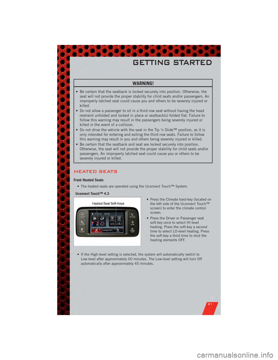
HEATED SEATS
Front Heated Seats
• The heated seats are operated using the Uconnect Touch™ System.
Uconnect Touch™ 4.3 • Press the Climate hard-key (located onthe left side of the Uconnect Touch™
screen) to enter the climate control
screen.
• Press the Driver or Passenger seat soft-key once to select HI-level
heating. Press the soft-key a second
time to select LO-level heating. Press
the soft-key a third time to shut the
heating elements OFF.
• If the High-level setting is selected, the system will automatically switch to Low-level after approximately 60 minutes. The Low-level setting will turn Off
automatically after approximately 45 minutes.
GETTING STARTED
21
Page 60 of 108
PROGRAMMABLE FEATURES
Electronic Vehicle Information Center (EVIC) – If Equipped
• The EVIC can be used to view or change the following settings. Press the UP
or DOWNbutton until System Setup displays, then press the SELECT
button. Scroll through the settings using the UP or DOWN buttons. Press the
SELECTbutton to change the setting. Press the BACK button to scroll back to
a previous menu or sub menu.
• Fuel Economy: • Average Fuel Economy/Fuel Saver Mode
• Distance To Empty (DTE)
• Miles Per Gallon (MPG) • Trip Info
• Trip A
• Trip B
• Elapsed Time
• Vehicle Speed • Units
• To Reset The Display • Vehicle Info (Customer Information Features)
Uconnect Touch™ 4.3 Customer Programmable Features
• The Uconnect Touch™ 4.3 system allows you to access Customer Programmable
feature settings such as Display, Clock, Safety/Assistance, Lights, Doors & Locks,
Heated Seats, Engine Off Operation, Compass Settings, Audio, Phone/ Bluetooth
and SIRIUS Setup through hard-keys and soft-keys.
• Press the Settings hard-key to on the right side of the unit to access the Settings screen, use the Page Up/Down soft-keys to scroll through the following settings.
The following feature settings are available:
• Display • Engine Off Options
• Clock • Compass Settings
• Safety / Assistance • Audio
• Lights • Phone / Bluetooth
• Doors & Locks • SIRIUS Setup
• Heated Seats
ELECTRONICS
58
Page 61 of 108
Uconnect Touch™ 8.4 Customer Programmable Features
• The Uconnect Touch™ 8.4 system allows you to access Customer Programmablefeature settings such as Display, Clock, Safety/Assistance, Lights, Doors & Locks,
Heated Seats, Engine Off Operation, Compass Settings, Audio, Phone/ Bluetooth
and SIRIUS Setup through soft-keys.
• Touch the More soft-key to on the bottom of the screen, then touch the Settings soft-key to access the Settings screen. When making a selection, scroll up or down
until the preferred setting is highlighted, then press and release the preferred
setting until a check-mark appears next to the setting, showing that setting has
been selected. The following feature settings are available:
• Display • Engine Off Options
• Clock • Compass Settings
• Safety / Assistance • Audio
• Lights • Phone / Bluetooth
• Doors & Locks • SIRIUS Setup
• Heated Seats
UNIVERSAL GARAGE DOOR OPENER
(HomeLink®)
Programming HomeLink®
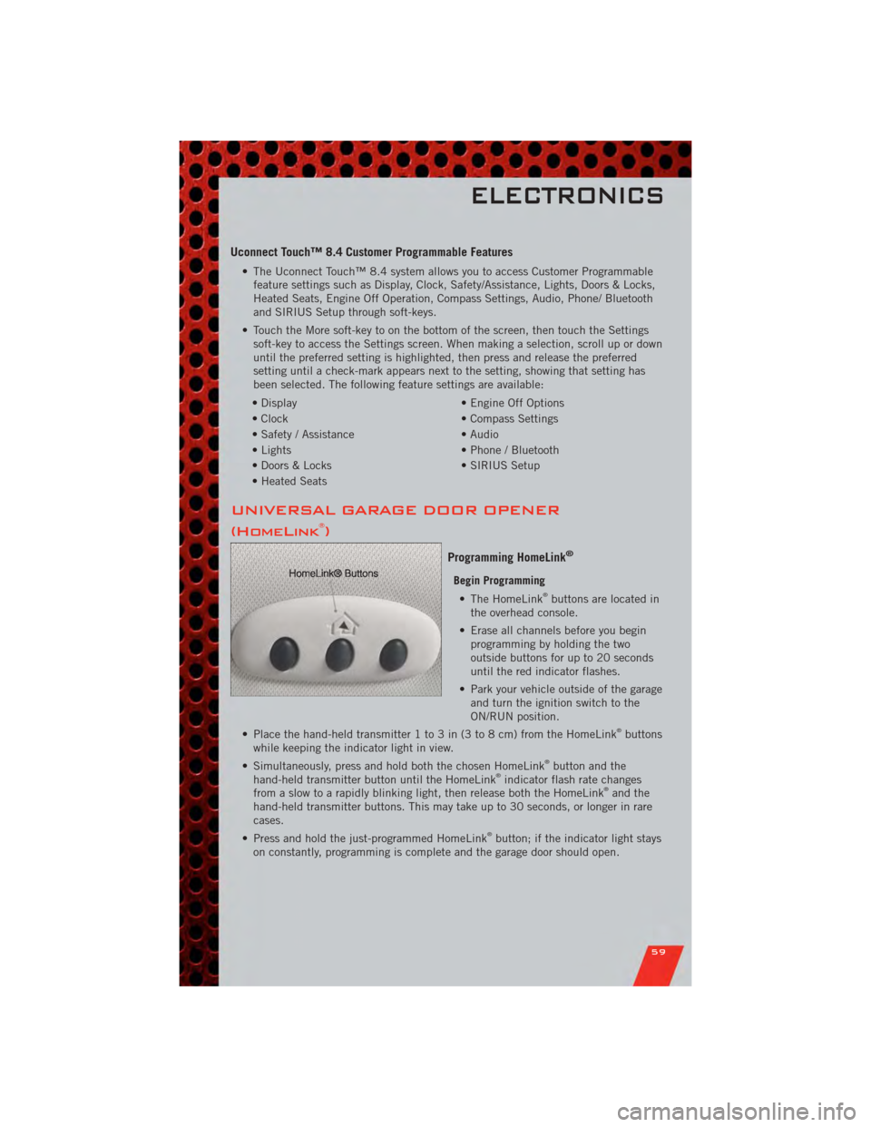
Begin Programming • The HomeLink®buttons are located in
the overhead console.
• Erase all channels before you begin programming by holding the two
outside buttons for up to 20 seconds
until the red indicator flashes.
• Park your vehicle outside of the garage and turn the ignition switch to the
ON/RUN position.
• Place the hand-held transmitter 1 to 3 in (3 to 8 cm) from the HomeLink
®buttons
while keeping the indicator light in view.
• Simultaneously, press and hold both the chosen HomeLink
®button and the
hand-held transmitter button until the HomeLink®indicator flash rate changes
from a slow to a rapidly blinking light, then release both the HomeLink®and the
hand-held transmitter buttons. This may take up to 30 seconds, or longer in rare
cases.
• Press and hold the just-programmed HomeLink
®button; if the indicator light stays
on constantly, programming is complete and the garage door should open.
ELECTRONICS
59