ignition DODGE JOURNEY 2014 1.G Owner's Manual
[x] Cancel search | Manufacturer: DODGE, Model Year: 2014, Model line: JOURNEY, Model: DODGE JOURNEY 2014 1.GPages: 124, PDF Size: 3.37 MB
Page 75 of 124
ROADSIDE ASSISTANCE
Dial toll-free 1-800-521-2779 for U.S. Residents or 1-800-363-4869 for Canadian Residents.
• Provide your name, vehicle identification number, license plate number, and your loca-tion, including the telephone number from which you are calling.
• Briefly describe the nature of the problem and answer a few simple questions.
• You will be given the name of the service provider and an estimated time of arrival. If you feel you are in an “unsafe situation”, please let us know. With your consent, we will
contact local police or safety authorities.
INSTRUMENT CLUSTER WARNING LIGHTS
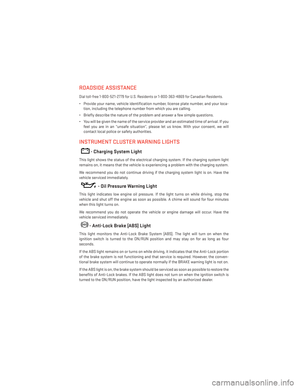
- Charging System Light
This light shows the status of the electrical charging system. If the charging system light
remains on, it means that the vehicle is experiencing a problem with the charging system.
We recommend you do not continue driving if the charging system light is on. Have the
vehicle serviced immediately.
- Oil Pressure Warning Light
This light indicates low engine oil pressure. If the light turns on while driving, stop the
vehicle and shut off the engine as soon as possible. A chime will sound for four minutes
when this light turns on.
We recommend you do not operate the vehicle or engine damage will occur. Have the
vehicle serviced immediately.
- Anti-Lock Brake (ABS) Light
This light monitors the Anti-Lock Brake System (ABS). The light will turn on when the
ignition switch is turned to the ON/RUN position and may stay on for as long as four
seconds.
If the ABS light remains on or turns on while driving, it indicates that the Anti-Lock portion
of the brake system is not functioning and that service is required. However, the conven-
tional brake system will continue to operate normally if the BRAKE warning light is not on.
If the ABS light is on, the brake system should be serviced as soon as possible to restore the
benefits of Anti-Lock brakes. If the ABS light does not turn on when the ignition switch is
turned to the ON/RUN position, have the light inspected by an authorized dealer.
WHAT TO DO IN EMERGENCIES
73
Page 76 of 124
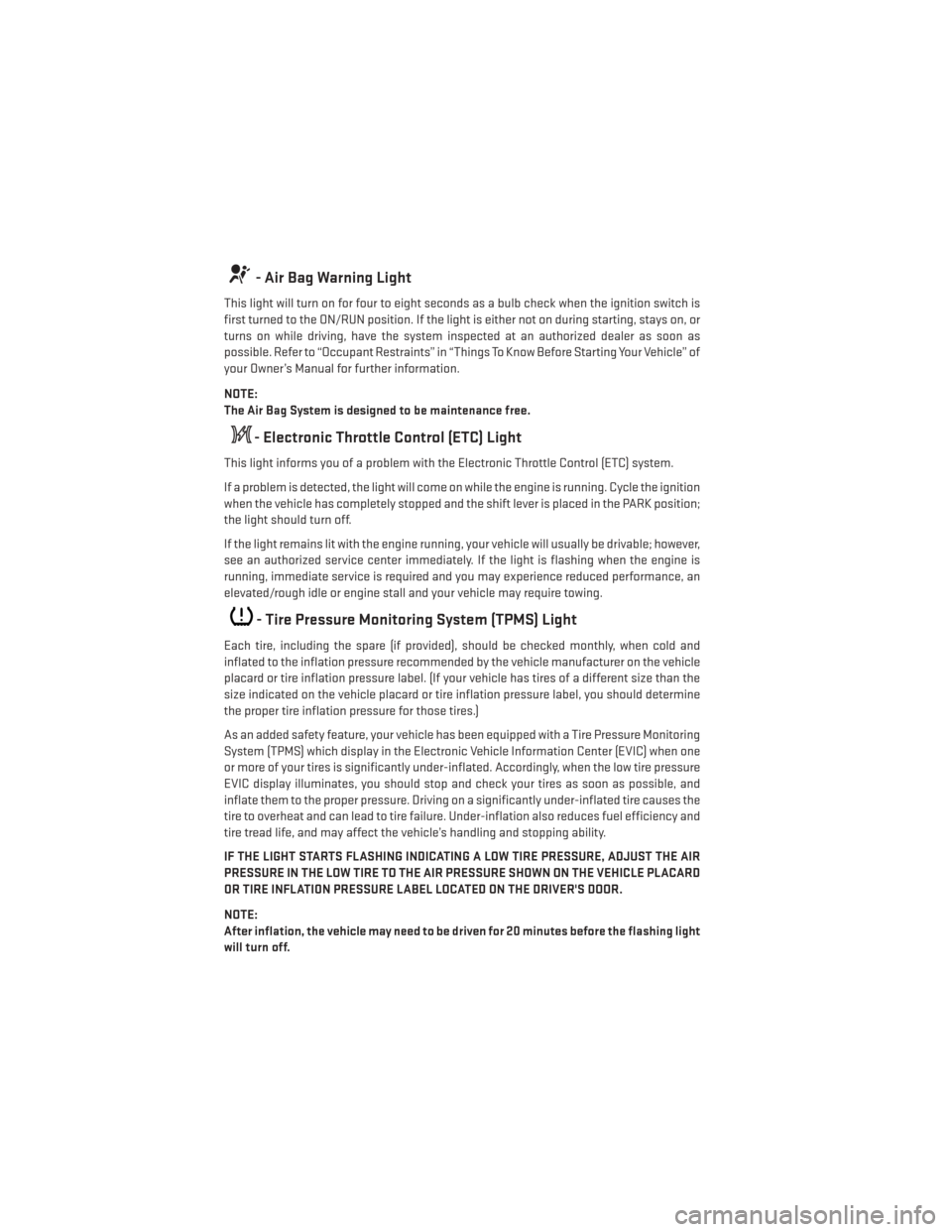
- Air Bag Warning Light
This light will turn on for four to eight seconds as a bulb check when the ignition switch is
first turned to the ON/RUN position. If the light is either not on during starting, stays on, or
turns on while driving, have the system inspected at an authorized dealer as soon as
possible. Refer to “Occupant Restraints” in “Things To Know Before Starting Your Vehicle” of
your Owner’s Manual for further information.
NOTE:
The Air Bag System is designed to be maintenance free.
- Electronic Throttle Control (ETC) Light
This light informs you of a problem with the Electronic Throttle Control (ETC) system.
If a problem is detected, the light will come on while the engine is running. Cycle the ignition
when the vehicle has completely stopped and the shift lever is placed in the PARK position;
the light should turn off.
If the light remains lit with the engine running, your vehicle will usually be drivable; however,
see an authorized service center immediately. If the light is flashing when the engine is
running, immediate service is required and you may experience reduced performance, an
elevated/rough idle or engine stall and your vehicle may require towing.
- Tire Pressure Monitoring System (TPMS) Light
Each tire, including the spare (if provided), should be checked monthly, when cold and
inflated to the inflation pressure recommended by the vehicle manufacturer on the vehicle
placard or tire inflation pressure label. (If your vehicle has tires of a different size than the
size indicated on the vehicle placard or tire inflation pressure label, you should determine
the proper tire inflation pressure for those tires.)
As an added safety feature, your vehicle has been equipped with a Tire Pressure Monitoring
System (TPMS) which display in the Electronic Vehicle Information Center (EVIC) when one
or more of your tires is significantly under-inflated. Accordingly, when the low tire pressure
EVIC display illuminates, you should stop and check your tires as soon as possible, and
inflate them to the proper pressure. Driving on a significantly under-inflated tire causes the
tire to overheat and can lead to tire failure. Under-inflation also reduces fuel efficiency and
tire tread life, and may affect the vehicle’s handling and stopping ability.
IF THE LIGHT STARTS FLASHING INDICATING A LOW TIRE PRESSURE, ADJUST THE AIR
PRESSURE IN THE LOW TIRE TO THE AIR PRESSURE SHOWN ON THE VEHICLE PLACARD
OR TIRE INFLATION PRESSURE LABEL LOCATED ON THE DRIVER'S DOOR.
NOTE:
After inflation, the vehicle may need to be driven for 20 minutes before the flashing light
will turn off.
WHAT TO DO IN EMERGENCIES
74
Page 78 of 124
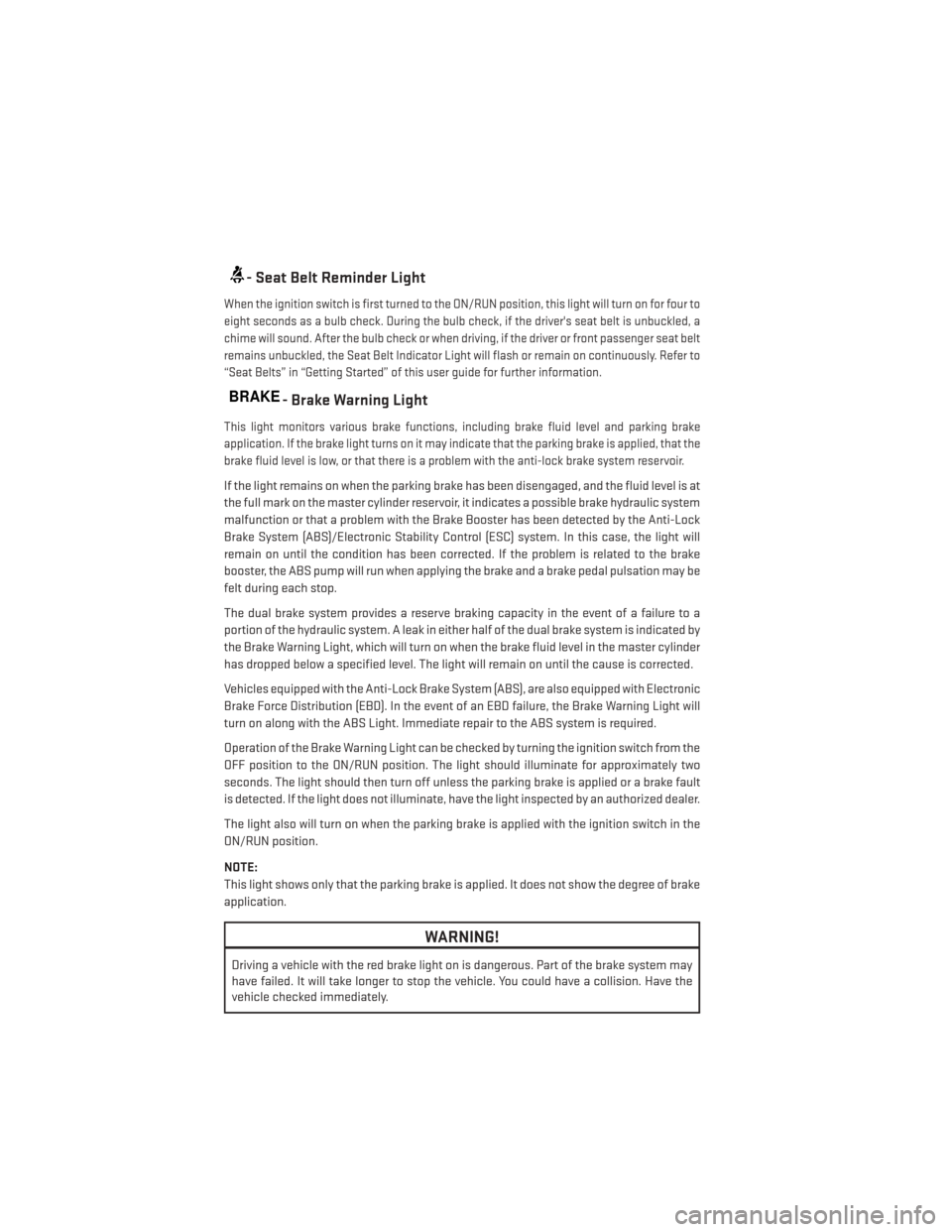
- Seat Belt Reminder Light
When the ignition switch is first turned to the ON/RUN position, this light will turn on for four to
eight seconds as a bulb check. During the bulb check, if the driver's seat belt is unbuckled, a
chime will sound. After the bulb check or when driving, if the driver or front passenger seat belt
remains unbuckled, the Seat Belt Indicator Light will flash or remain on continuously. Refer to
“Seat Belts” in “Getting Started” of this user guide for further information.
BRAKE- Brake Warning Light
This light monitors various brake functions, including brake fluid level and parking brake
application. If the brake light turns on it may indicate that the parking brake is applied, that the
brake fluid level is low, or that there is a problem with the anti-lock brake system reservoir.
If the light remains on when the parking brake has been disengaged, and the fluid level is at
the full mark on the master cylinder reservoir, it indicates a possible brake hydraulic system
malfunction or that a problem with the Brake Booster has been detected by the Anti-Lock
Brake System (ABS)/Electronic Stability Control (ESC) system. In this case, the light will
remain on until the condition has been corrected. If the problem is related to the brake
booster, the ABS pump will run when applying the brake and a brake pedal pulsation may be
felt during each stop.
The dual brake system provides a reserve braking capacity in the event of a failure to a
portion of the hydraulic system. A leak in either half of the dual brake system is indicated by
the Brake Warning Light, which will turn on when the brake fluid level in the master cylinder
has dropped below a specified level. The light will remain on until the cause is corrected.
Vehicles equipped with the Anti-Lock Brake System (ABS), are also equipped with Electronic
Brake Force Distribution (EBD). In the event of an EBD failure, the Brake Warning Light will
turn on along with the ABS Light. Immediate repair to the ABS system is required.
Operation of the Brake Warning Light can be checked by turning the ignition switch from the
OFF position to the ON/RUN position. The light should illuminate for approximately two
seconds. The light should then turn off unless the parking brake is applied or a brake fault
is detected. If the light does not illuminate, have the light inspected by an authorized dealer.
The light also will turn on when the parking brake is applied with the ignition switch in the
ON/RUN position.
NOTE:
This light shows only that the parking brake is applied. It does not show the degree of brake
application.
WARNING!
Driving a vehicle with the red brake light on is dangerous. Part of the brake system may
have failed. It will take longer to stop the vehicle. You could have a collision. Have the
vehicle checked immediately.
WHAT TO DO IN EMERGENCIES
76
Page 80 of 124
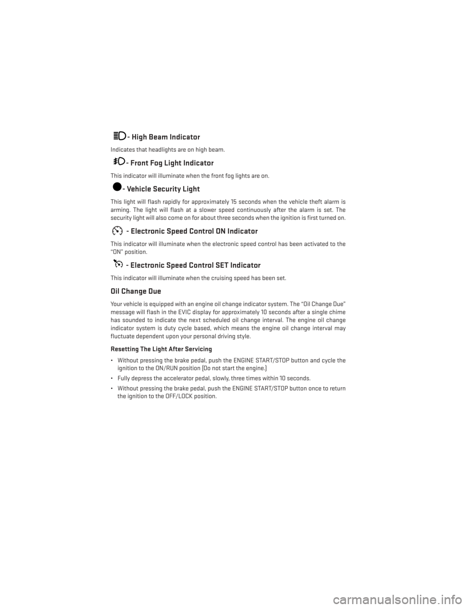
- High Beam Indicator
Indicates that headlights are on high beam.
- Front Fog Light Indicator
This indicator will illuminate when the front fog lights are on.
- Vehicle Security Light
This light will flash rapidly for approximately 15 seconds when the vehicle theft alarm is
arming. The light will flash at a slower speed continuously after the alarm is set. The
security light will also come on for about three seconds when the ignition is first turned on.
- Electronic Speed Control ON Indicator
This indicator will illuminate when the electronic speed control has been activated to the
“ON” position.
- Electronic Speed Control SET Indicator
This indicator will illuminate when the cruising speed has been set.
Oil Change Due
Your vehicle is equipped with an engine oil change indicator system. The “Oil Change Due”
message will flash in the EVIC display for approximately 10 seconds after a single chime
has sounded to indicate the next scheduled oil change interval. The engine oil change
indicator system is duty cycle based, which means the engine oil change interval may
fluctuate dependent upon your personal driving style.
Resetting The Light After Servicing
• Without pressing the brake pedal, push the ENGINE START/STOP button and cycle theignition to the ON/RUN position (Do not start the engine.)
• Fully depress the accelerator pedal, slowly, three times within 10 seconds.
• Without pressing the brake pedal, push the ENGINE START/STOP button once to return the ignition to the OFF/LOCK position.
WHAT TO DO IN EMERGENCIES
78
Page 83 of 124
5. Turn OFF the ignition.
6. Block both the front and rear of the wheel diagonally opposite of the jacking position.For example, if changing the right front tire, block the left rear wheel.
NOTE:
Passengers should not remain in the vehicle
when the vehicle is being jacked.
Spare Tire Removal
NOTE:
On seven-passenger models, fold the third-row passenger seats flat. This will provide more
space when accessing the jacking tools and when operating the winch mechanism.
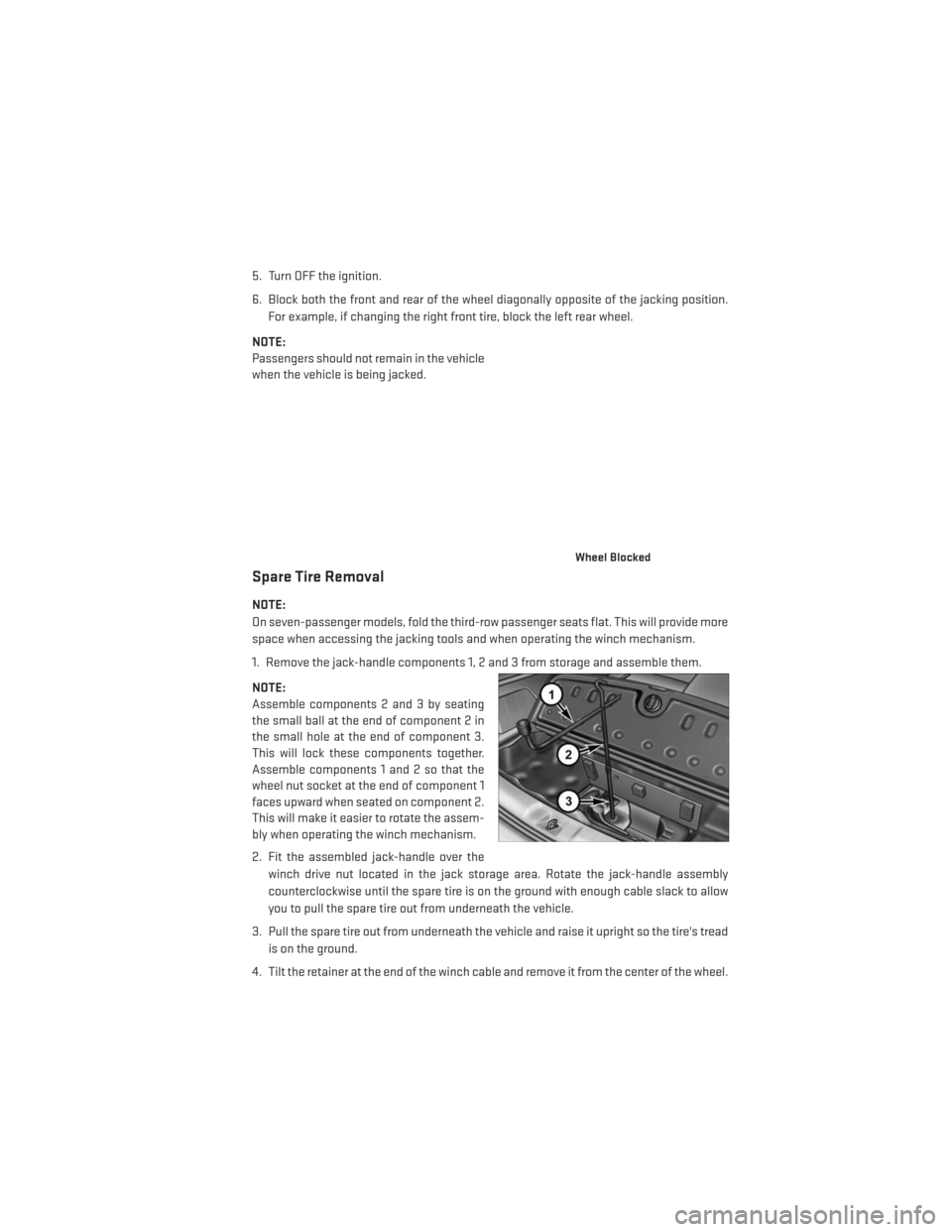
1. Remove the jack-handle components 1, 2 and 3 from storage and assemble them.
NOTE:
Assemble components 2 and 3 by seating
the small ball at the end of component 2 in
the small hole at the end of component 3.
This will lock these components together.
Assemble components 1 and 2 so that the
wheel nut socket at the end of component 1
faces upward when seated on component 2.
This will make it easier to rotate the assem-
bly when operating the winch mechanism.
2. Fit the assembled jack-handle over the winch drive nut located in the jack storage area. Rotate the jack-handle assembly
counterclockwise until the spare tire is on the ground with enough cable slack to allow
you to pull the spare tire out from underneath the vehicle.
3. Pull the spare tire out from underneath the vehicle and raise it upright so the tire's tread is on the ground.
4. Tilt the retainer at the end of the winch cable and remove it from the center of the wheel.
Wheel Blocked
WHAT TO DO IN EMERGENCIES
81
Page 89 of 124
JUMP-STARTING
• If your vehicle has a discharged battery itcan be jump-started using a set of jumper
cables and a battery in another vehicle or
by using a portable battery booster pack.
• Jump-starting can be dangerous if done improperly so please follow the proce-
dures in this section carefully.
NOTE:
When using a portable battery booster pack
follow the manufacturer's operating instruc-
tions and precautions.
Preparations For Jump-Start
• The battery in your vehicle is located between the left front headlight assembly and the left front wheel splash shield. To allow jump-starting there are remote battery posts
located on the left side of the engine compartment.
• Set the parking brake, shift the automatic transmission into PARK and turn the ignition to LOCK.
• Turn off the heater, radio, and all unnecessary electrical accessories.
• Remove the protective cover over the remote positive (+)battery post. To remove the
cover, press the locking tab and pull upward on the cover.
• If using another vehicle to jump-start the battery, park the vehicle within the jumper cables reach, set the parking brake and make sure the ignition is OFF.
Jump-Starting Procedure
1. Connect the positive (+)end of the jumper cable to the remote positive (+)post of the
vehicle with discharged battery.
2. Connect the opposite end of the positive (+)jumper cable to the positive (+)post of the
booster battery.
3. Connect the negative end (-)of the jumper cable to the negative (-)post of the booster
battery.
WHAT TO DO IN EMERGENCIES
87
Page 91 of 124
WARNING!
• When temperatures are below the freezing point, electrolyte in a discharged batterymay freeze. Do not attempt jump-starting because the battery could rupture or
explode and cause personal injury. Battery temperature must be brought above the
freezing point before attempting a jump-start.
• Take care to avoid the radiator cooling fan whenever the hood is raised. It can start anytime the ignition switch is on. You can be injured by moving fan blades.
• Remove any metal jewelry, such as watch bands or bracelets, that might make an
inadvertent electrical contact. You could be severely injured.
• Batteries contain sulfuric acid that can burn your skin or eyes and generate hydrogen
gas which is flammable and explosive. Keep open flames or sparks away from the
battery.
• Do not allow vehicles to touch each other as this could establish a ground connection
and personal injury could result.
• Failure to follow this procedure could result in personal injury or property damage
due to battery explosion.
• Do not connect the cable to the negative post (-) of the discharged battery. The resulting electrical spark could cause the battery to explode and could result in
personal injury.
SHIFT LEVER OVERRIDE
• If a malfunction occurs and the shift lever cannot be moved out of the PARK position, youcan use the following procedure to temporarily move the shift lever:
1.
To access the shift lever override, remove the cubby bin liner located in the center
console behind the shift lever. The override access port is at the front of the cubby bin.
2. Firmly set the parking brake.
3. Turn the ignition switch to the ACC or ON position without starting the engine.
4. Press and maintain firm pressure on the brake pedal.
5. Using a screwdriver or similar tool, press and hold the override tab through the access port on the center console.
6. Move the shift lever into the NEUTRAL position.
7. The vehicle may then be started in NEUTRAL.
8. Reinstall the override cover.
WHAT TO DO IN EMERGENCIES
89
Page 105 of 124
FUSES
Interior Fuses
• The interior fuse panel is located on the passenger side under the instrument panel.
Cavity Cartridge Fuse Mini-FuseDescription
F100 30 Amp Pink 110V AC Inverter – If Equipped
F101 10 Amp RedInterior Lights
F102 20 Amp YellowCigar Lighter in Instrument Panel/
Left Rear Power Outlet
F103 20 Amp YellowPower Outlet in Console Bin/Power
Outlet in Rear of Console
F105 20 Amp Yellow Heated Seats – If Equipped
F106 20 Amp YellowRear Power Outlet
F107 10 Amp Red Rear Camera – If Equipped
F108 15 Amp BlueInstrument Panel
F109 10 Amp RedClimate Control/HVAC
F110 10 Amp Red Occupant Restraint Controller
F112 10 Amp Red Spare
F114 20 Amp Yellow Rear HVAC Blower/Motor
F115 20 Amp YellowRear Wiper Motor
F116 30 Amp Pink Rear Defroster (EBL)
F117 10 Amp RedHeated Mirrors
F118 10 Amp Red Occupant Restraint Controller
F119 10 Amp Red Steering Column Control Module
F120 10 Amp Red All Wheel Drive – If Equipped
F121 15 Amp Blue Wireless Ignition Node
F122 25 Amp Natural Driver Door Module
F123 25 Amp Natural Passenger Door Module
F124 10 Amp RedMirrors
F125 10 Amp Red Steering Column Control Module
F126 25 Amp NaturalAudio Amplifier
F127 20 Amp Yellow Trailer Tow – If Equipped
F128 15 Amp Blue Radio
F129 15 Amp Blue Video/DVD – If Equipped
F130 15 Amp Blue Climate Control/Instrument Panel
F131 10 Amp RedPassenger Assistance/Hands Free
System – If Equipped
F132 10 Amp RedTire Pressure Module
F133 10 Amp RedSpare
MAINTAINING YOUR VEHICLE
103
Page 106 of 124
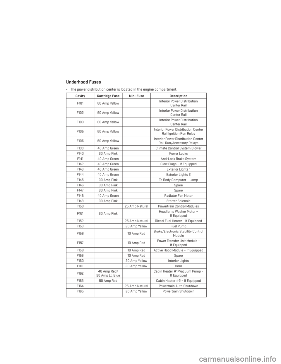
Underhood Fuses
• The power distribution center is located in the engine compartment.
Cavity Cartridge Fuse Mini-FuseDescription
F101 60 Amp Yellow Interior Power Distribution
Center Rail
F102 60 Amp Yellow Interior Power Distribution
Center Rail
F103 60 Amp Yellow Interior Power Distribution
Center Rail
F105 60 Amp Yellow Interior Power Distribution Center
Rail Ignition Run Relay
F106 60 Amp Yellow Interior Power Distribution Center
Rail Run/Accessory Relays
F139 40 Amp Green Climate Control System Blower
F140 30 Amp Pink Power Locks
F141 40 Amp Green Anti-Lock Brake System
F142 40 Amp Green Glow Plugs – If Equipped
F143 40 Amp Green Exterior Lights 1
F144 40 Amp Green Exterior Lights 2
F145 30 Amp Pink To Body Computer – Lamp
F146 30 Amp Pink Spare
F147 30 Amp Pink Spare
F148 40 Amp Green Radiator Fan Motor
F149 30 Amp Pink Starter Solenoid
F150 25 Amp Natural Powertrain Control Modules
F151 30 Amp Pink Headlamp Washer Motor –
If Equipped
F152 25 Amp Natural Diesel Fuel Heater – If Equipped
F153 20 Amp YellowFuel Pump
F156 10 Amp RedBrake/Electronic Stability Control
Module
F157 10 Amp RedPower Transfer Unit Module –
If Equipped
F158 10 Amp Red Active Hood Module – If Equipped
F159 10 Amp RedSpare
F160 20 Amp YellowInterior Lights
F161 20 Amp Yellow Horn
F162 40 Amp Red/
20 Amp Lt. Blue Cabin Heater #1/Vacuum Pump –
If Equipped
F163 50 Amp Red Cabin Heater #2 – If Equipped
F164 25 Amp Natural Powertrain Auto Shutdown
F165 20 Amp Yellow Powertrain Shutdown
MAINTAINING YOUR VEHICLE
104