lock DODGE JOURNEY 2014 1.G Owner's Manual
[x] Cancel search | Manufacturer: DODGE, Model Year: 2014, Model line: JOURNEY, Model: DODGE JOURNEY 2014 1.GPages: 124, PDF Size: 3.37 MB
Page 67 of 124
Compass Calibration
This compass is self-calibrating, which eliminates the need to set the compass manually.
When the vehicle is new, the compass may appear erratic and the EVIC will display “CAL”
until the compass is calibrated.
You may also calibrate the compass by completing one or more 360 degree turns (in an area
free from large metal or metallic objects) until the “CAL” message displayed in the EVIC
turns off. The compass will now function normally.
PROGRAMMABLE FEATURES
Electronic Vehicle Information Center (EVIC) — If Equipped
• The EVIC can be used to view or change the following settings. Press the UPor
DOWN
button until System Setup displays, then press the SELECTbutton. Scroll
through the settings using the UP or DOWN buttons. Press the SELECT
button to
change the setting. Press the BACK button to scroll back to a previous menu or sub
menu.
• Fuel Economy • Average Fuel Economy
• Distance To Empty (DTE)
• Miles Per Gallon (MPG) • Trip Info
• Trip A
• Trip B
• Elapsed Time
• Vehicle Speed • Tire PSI
• Messages •
Vehicle Info (Customer Information
Features)
Uconnect® 4.3 Customer Programmable Features
• The Uconnect® 4.3 system allows you to access Customer Programmable feature set- tings such as Display, Clock, Safety/Assistance, Lights, Doors & Locks, Heated Seats,
Engine Off Operation, Compass Settings, Audio, Phone/ Bluetooth® and SIRIUS Setup
through hard-keys and soft-keys.
• Press the “Settings” hard-key to on the right side of the unit to access the Settings screen, use the “Page Up/Down” soft-keys to scroll through the following settings. The
following feature settings are available:
• Display • Auto On Comfort & Remote Start
• Clock • Engine Off Options
• Safety/Assistance • Audio
• Lights • Phone/Bluetooth®
• Doors & Locks • SIRIUS Setup
ELECTRONICS
65
Page 68 of 124
Uconnect® 8.4 Customer Programmable Features
• The Uconnect® 8.4 system allows you to access Customer Programmable feature set-tings such as Display, Clock, Safety/Assistance, Lights, Doors & Locks, Heated Seats,
Engine Off Operation, Compass Settings, Audio, Phone/Bluetooth® and SIRIUS Setup
through soft-keys.
• Touch the “More” soft-key on the bottom of the screen, then touch the “Settings” soft-key to access the Settings screen. When making a selection, scroll up or down until
the preferred setting is highlighted, then press and release the preferred setting until a
check-mark appears next to the setting, showing that setting has been selected.
The following feature settings are available:
• Display • Auto On Comfort & Remote Start
• Clock • Engine Off Options
• Safety/Assistance • Audio
• Lights • Phone/Bluetooth®
• Doors & Locks • SIRIUS Setup
UNIVERSAL GARAGE DOOR OPENER (HomeLink®)
• HomeLink® replaces up to three hand-held transmitters that operate devices such as
garage door openers, motorized gates, lighting or home security systems. The
HomeLink® unit is powered by your vehicles 12 Volt battery.
• The HomeLink® buttons that are located in the overhead console or sunvisor designate the three different HomeLink® channels.
• The HomeLink® indicator is located above the center button.
Before You Begin Programming
HomeLink®
Ensure that your vehicle is parked outside of
the garage before you begin programming.
For efficient programming and accurate
transmission of the radio-frequency signal,
it is recommended that a new battery be
placed in the hand-held transmitter of the
device that is being programmed to the
HomeLink® system.
Erase all channels before you begin pro-
gramming. To erase the channels, place the
ignition switch into the ON/RUN position,
then press and hold the two outside HomeLink® buttons (I and III) for up to 20 seconds or
until the red indicator flashes.
ELECTRONICS
66
Page 70 of 124
Programming A Non-Rolling Code
NOTE:
For programming Garage Door Openers manufactured before 1995.
1. Turn the ignition switch to the ON/RUN position.
2. Place the hand-held transmitter 1 to 3 inches (3 to 8 cm) away from the HomeLink®button you wish to program while keeping the HomeLink® indicator light in view.
3. Simultaneously press and hold both the HomeLink® button you want to program and the hand-held transmitter button.
4. Continue to hold both buttons and observe the indicator light. The HomeLink® indicator will flash slowly and then rapidly after HomeLink® has received the frequency signal
from the hand-held transmitter. Release both buttons after the indicator light changes
from slow to rapid.
5. Press and hold the programmed HomeLink® button and observe the indicator light. If the indicator light stays on constantly, programming is complete and the garage door
(or device) should activate when the HomeLink® button is pressed.
6. To program the two remaining HomeLink® buttons, repeat each step for each remaining button. DO NOT erase the channels.
Using HomeLink®
• To operate, press and release the programmed HomeLink® button. Activation will nowoccur for the programmed device (e.g., garage door opener, gate operator, security
system, entry door lock, home/office lighting, etc.,). The hand-held transmitter of the
device may also be used at any time.
WARNING!
• Your motorized door or gate will open and close while you are programming the
universal transceiver. Do not program the transceiver if people or pets are in the path
of the door or gate.
• Do not run your vehicle in a closed garage or confined area while programming the
transceiver. Exhaust gas from your vehicle contains Carbon Monoxide (CO) which is
odorless and colorless. Carbon Monoxide is poisonous when inhaled and can cause
you and others to be severely injured or killed.
ELECTRONICS
68
Page 72 of 124
POWER OUTLETS
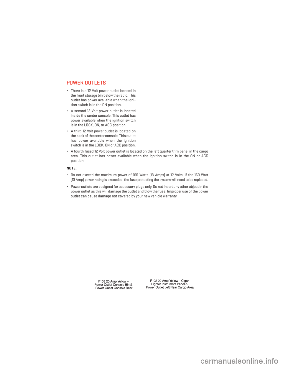
• There is a 12 Volt power outlet located inthe front storage bin below the radio. This
outlet has power available when the igni-
tion switch is in the ON position.
• A second 12 Volt power outlet is located inside the center console. This outlet has
power available when the ignition switch
is in the LOCK, ON, or ACC position.
• A third 12 Volt power outlet is located on the back of the center console. This outlet
has power available when the ignition
switch is in the LOCK, ON or ACC position.
• A fourth fused 12 Volt power outlet is located on the left quarter trim panel in the cargo area. This outlet has power available when the ignition switch is in the ON or ACC
position.
NOTE:
•
Do not exceed the maximum power of 160 Watts (13 Amps) at 12 Volts. If the 160 Watt
(13 Amp) power rating is exceeded, the fuse protecting the system will need to be replaced.
• Power outlets are designed for accessory plugs only. Do not insert any other object in the power outlet as this will damage the outlet and blow the fuse. Improper use of the power
outlet can cause damage not covered by your new vehicle warranty.
ELECTRONICS
70
Page 75 of 124
ROADSIDE ASSISTANCE
Dial toll-free 1-800-521-2779 for U.S. Residents or 1-800-363-4869 for Canadian Residents.
• Provide your name, vehicle identification number, license plate number, and your loca-tion, including the telephone number from which you are calling.
• Briefly describe the nature of the problem and answer a few simple questions.
• You will be given the name of the service provider and an estimated time of arrival. If you feel you are in an “unsafe situation”, please let us know. With your consent, we will
contact local police or safety authorities.
INSTRUMENT CLUSTER WARNING LIGHTS
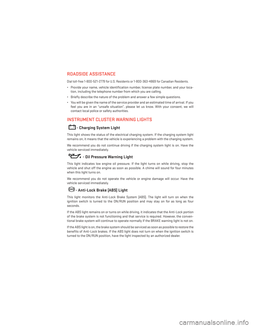
- Charging System Light
This light shows the status of the electrical charging system. If the charging system light
remains on, it means that the vehicle is experiencing a problem with the charging system.
We recommend you do not continue driving if the charging system light is on. Have the
vehicle serviced immediately.
- Oil Pressure Warning Light
This light indicates low engine oil pressure. If the light turns on while driving, stop the
vehicle and shut off the engine as soon as possible. A chime will sound for four minutes
when this light turns on.
We recommend you do not operate the vehicle or engine damage will occur. Have the
vehicle serviced immediately.
- Anti-Lock Brake (ABS) Light
This light monitors the Anti-Lock Brake System (ABS). The light will turn on when the
ignition switch is turned to the ON/RUN position and may stay on for as long as four
seconds.
If the ABS light remains on or turns on while driving, it indicates that the Anti-Lock portion
of the brake system is not functioning and that service is required. However, the conven-
tional brake system will continue to operate normally if the BRAKE warning light is not on.
If the ABS light is on, the brake system should be serviced as soon as possible to restore the
benefits of Anti-Lock brakes. If the ABS light does not turn on when the ignition switch is
turned to the ON/RUN position, have the light inspected by an authorized dealer.
WHAT TO DO IN EMERGENCIES
73
Page 78 of 124
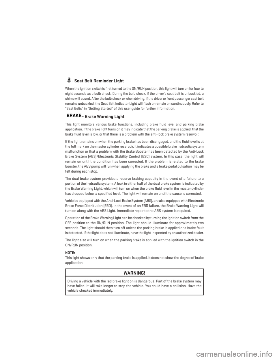
- Seat Belt Reminder Light
When the ignition switch is first turned to the ON/RUN position, this light will turn on for four to
eight seconds as a bulb check. During the bulb check, if the driver's seat belt is unbuckled, a
chime will sound. After the bulb check or when driving, if the driver or front passenger seat belt
remains unbuckled, the Seat Belt Indicator Light will flash or remain on continuously. Refer to
“Seat Belts” in “Getting Started” of this user guide for further information.
BRAKE- Brake Warning Light
This light monitors various brake functions, including brake fluid level and parking brake
application. If the brake light turns on it may indicate that the parking brake is applied, that the
brake fluid level is low, or that there is a problem with the anti-lock brake system reservoir.
If the light remains on when the parking brake has been disengaged, and the fluid level is at
the full mark on the master cylinder reservoir, it indicates a possible brake hydraulic system
malfunction or that a problem with the Brake Booster has been detected by the Anti-Lock
Brake System (ABS)/Electronic Stability Control (ESC) system. In this case, the light will
remain on until the condition has been corrected. If the problem is related to the brake
booster, the ABS pump will run when applying the brake and a brake pedal pulsation may be
felt during each stop.
The dual brake system provides a reserve braking capacity in the event of a failure to a
portion of the hydraulic system. A leak in either half of the dual brake system is indicated by
the Brake Warning Light, which will turn on when the brake fluid level in the master cylinder
has dropped below a specified level. The light will remain on until the cause is corrected.
Vehicles equipped with the Anti-Lock Brake System (ABS), are also equipped with Electronic
Brake Force Distribution (EBD). In the event of an EBD failure, the Brake Warning Light will
turn on along with the ABS Light. Immediate repair to the ABS system is required.
Operation of the Brake Warning Light can be checked by turning the ignition switch from the
OFF position to the ON/RUN position. The light should illuminate for approximately two
seconds. The light should then turn off unless the parking brake is applied or a brake fault
is detected. If the light does not illuminate, have the light inspected by an authorized dealer.
The light also will turn on when the parking brake is applied with the ignition switch in the
ON/RUN position.
NOTE:
This light shows only that the parking brake is applied. It does not show the degree of brake
application.
WARNING!
Driving a vehicle with the red brake light on is dangerous. Part of the brake system may
have failed. It will take longer to stop the vehicle. You could have a collision. Have the
vehicle checked immediately.
WHAT TO DO IN EMERGENCIES
76
Page 80 of 124
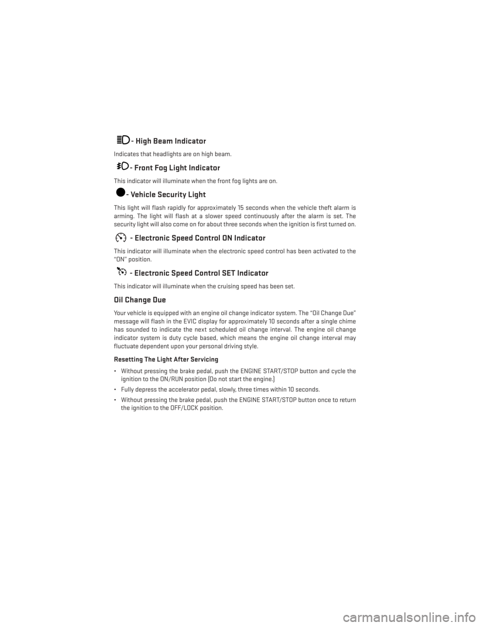
- High Beam Indicator
Indicates that headlights are on high beam.
- Front Fog Light Indicator
This indicator will illuminate when the front fog lights are on.
- Vehicle Security Light
This light will flash rapidly for approximately 15 seconds when the vehicle theft alarm is
arming. The light will flash at a slower speed continuously after the alarm is set. The
security light will also come on for about three seconds when the ignition is first turned on.
- Electronic Speed Control ON Indicator
This indicator will illuminate when the electronic speed control has been activated to the
“ON” position.
- Electronic Speed Control SET Indicator
This indicator will illuminate when the cruising speed has been set.
Oil Change Due
Your vehicle is equipped with an engine oil change indicator system. The “Oil Change Due”
message will flash in the EVIC display for approximately 10 seconds after a single chime
has sounded to indicate the next scheduled oil change interval. The engine oil change
indicator system is duty cycle based, which means the engine oil change interval may
fluctuate dependent upon your personal driving style.
Resetting The Light After Servicing
• Without pressing the brake pedal, push the ENGINE START/STOP button and cycle theignition to the ON/RUN position (Do not start the engine.)
• Fully depress the accelerator pedal, slowly, three times within 10 seconds.
• Without pressing the brake pedal, push the ENGINE START/STOP button once to return the ignition to the OFF/LOCK position.
WHAT TO DO IN EMERGENCIES
78
Page 83 of 124
5. Turn OFF the ignition.
6. Block both the front and rear of the wheel diagonally opposite of the jacking position.For example, if changing the right front tire, block the left rear wheel.
NOTE:
Passengers should not remain in the vehicle
when the vehicle is being jacked.
Spare Tire Removal
NOTE:
On seven-passenger models, fold the third-row passenger seats flat. This will provide more
space when accessing the jacking tools and when operating the winch mechanism.
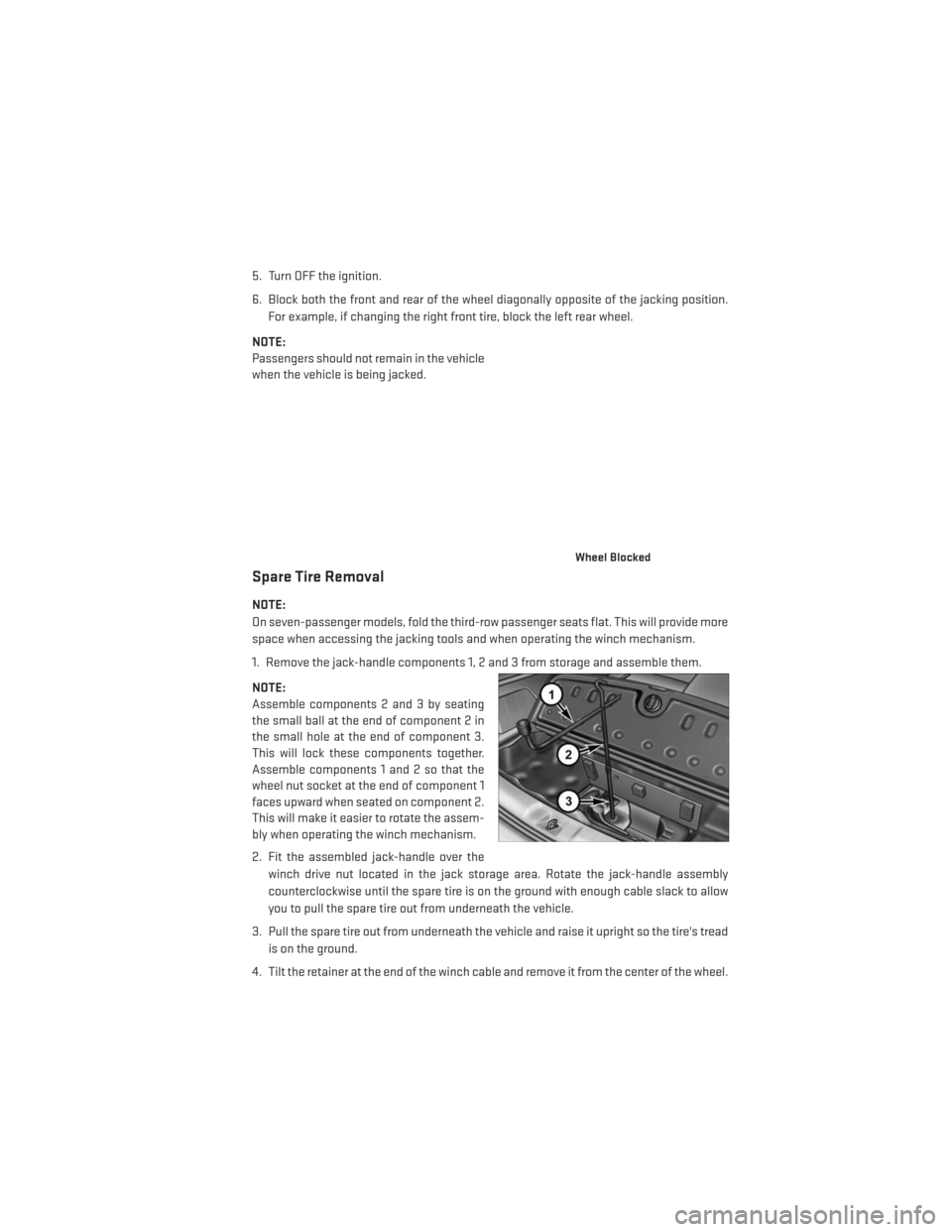
1. Remove the jack-handle components 1, 2 and 3 from storage and assemble them.
NOTE:
Assemble components 2 and 3 by seating
the small ball at the end of component 2 in
the small hole at the end of component 3.
This will lock these components together.
Assemble components 1 and 2 so that the
wheel nut socket at the end of component 1
faces upward when seated on component 2.
This will make it easier to rotate the assem-
bly when operating the winch mechanism.
2. Fit the assembled jack-handle over the winch drive nut located in the jack storage area. Rotate the jack-handle assembly
counterclockwise until the spare tire is on the ground with enough cable slack to allow
you to pull the spare tire out from underneath the vehicle.
3. Pull the spare tire out from underneath the vehicle and raise it upright so the tire's tread is on the ground.
4. Tilt the retainer at the end of the winch cable and remove it from the center of the wheel.
Wheel Blocked
WHAT TO DO IN EMERGENCIES
81
Page 84 of 124
Spare Tire Stowage
NOTE:
Refer to “Spare Tire Removal” for information on assembling the winch tools.
1.
Place the spare tire near to the winch cable. Hold the spare upright so that the tire's tread is on
the ground and the valve stem is at the top of the wheel facing away from the rear of the
vehicle.
2. Tilt the retainer at the end of the winch cable and drop it through the center of the wheel. Then place the spare tire with the cable and retainer underneath the vehicle.
3.
Fit the assembled jack-handle over the winch drive nut. Rotate the jack-handle assembly
clockwise to raise the spare tire into the storage area. Continue to rotate the jack-handle
assembly until you hear the winch mechanism click three times. It cannot be over tightened.
Push against the tire several times to be sure it is held securely in place.
Jacking Instructions
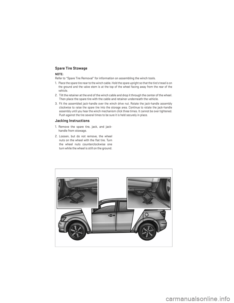
1. Remove the spare tire, jack, and jack-
handle from stowage.
2. Loosen, but do not remove, the wheel nuts on the wheel with the flat tire. Turn
the wheel nuts counterclockwise one
turn while the wheel is still on the ground.
WHAT TO DO IN EMERGENCIES
82
Page 85 of 124
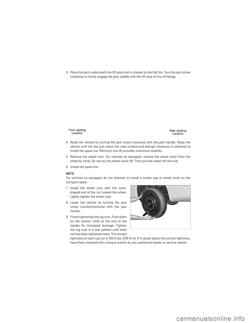
3. Place the jack underneath the lift area that is closest to the flat tire. Turn the jack screwclockwise to firmly engage the jack saddle with the lift area of the sill flange.
4. Raise the vehicle by turning the jack screw clockwise with the jack handle. Raise the vehicle until the tire just clears the road surface and enough clearance is obtained to
install the spare tire. Minimum tire lift provides maximum stability.
5. Remove the wheel nuts. For vehicles so equipped, remove the wheel cover from the wheel by hand. Do not pry the wheel cover off. Then pull the wheel off the hub.
6. Install the spare tire.
NOTE:
For vehicles so equipped, do not attempt to install a center cap or wheel cover on the
compact spare.
7. Install the wheel nuts with the cone- shaped end of the nut toward the wheel.
Lightly tighten the wheel nuts.
8. Lower the vehicle by turning the jack screw counterclockwise with the jack
handle.
9. Finish tightening the lug nuts. Push down on the wrench while at the end of the
handle for increased leverage. Tighten
the lug nuts in a star pattern until each
nut has been tightened twice. The correct
tightness of each lug nut is 100 ft.lbs. (135 N·m). If in doubt about the correct tightness,
have them checked with a torque wrench by you authorized dealer or service station.
WHAT TO DO IN EMERGENCIES
83