wheel DODGE JOURNEY 2014 1.G Owner's Manual
[x] Cancel search | Manufacturer: DODGE, Model Year: 2014, Model line: JOURNEY, Model: DODGE JOURNEY 2014 1.GPages: 124, PDF Size: 3.37 MB
Page 86 of 124
10. Lower the jack to its fully closed position.
11. Place the deflated (flat) tire in the cargo area.Do not stow the deflated tire in the spare
tire stowage location. Have the deflated (flat) tire repaired or replaced as soon as
possible.
12. To stow the winch cable and retainer, fit the assembled jack-handle over the winch drive nut. Rotate the jack-handle assembly clockwise until you hear the winch mechanism
click three times. It cannot be over tightened.
13. Stow the jack-handle and jack.
14. Check the tire pressure as soon as possible. Adjust the tire pressure as required.
Road Tire Installation
Vehicles Equipped With Wheel Covers
1. Mount the road tire on the axle.
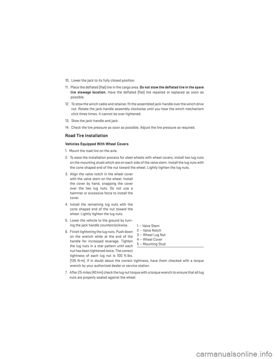
2. To ease the installation process for steel wheels with wheel covers, install two lug nuts on the mounting studs which are on each side of the valve stem. Install the lug nuts with
the cone shaped end of the nut toward the wheel. Lightly tighten the lug nuts.
3. Align the valve notch in the wheel cover with the valve stem on the wheel. Install
the cover by hand, snapping the cover
over the two lug nuts. Do not use a
hammer or excessive force to install the
cover.
4. Install the remaining lug nuts with the cone shaped end of the nut toward the
wheel. Lightly tighten the lug nuts.
5. Lower the vehicle to the ground by turn- ing the jack handle counterclockwise.
6. Finish tightening the lug nuts. Push down on the wrench while at the end of the
handle for increased leverage. Tighten
the lug nuts in a star pattern until each
nut has been tightened twice. The correct
tightness of each lug nut is 100 ft.lbs.
(135 N·m). If in doubt about the correct tightness, have them checked with a torque
wrench by your authorized dealer or service station.
7. After 25 miles (40 km) check the lug nut torque with a torque wrench to ensure that all lug nuts are properly seated against the wheel.
1 — Valve Stem
2 — Valve Notch
3 — Wheel Lug Nut
4 — Wheel Cover
5 — Mounting Stud
WHAT TO DO IN EMERGENCIES
84
Page 87 of 124
Vehicles Without Wheel Covers
1. Mount the road tire on the axle.
2. Install the remaining lug nuts with the cone shaped end of the nut toward the wheel.Lightly tighten the lug nuts.
3. Lower the vehicle to the ground by turning the jack handle counterclockwise.
4. Finish tightening the lug nuts. Push down on the wrench while at the end of the handle for increased leverage. Tighten the lug nuts in a star pattern until each nut has been
tightened twice. The correct tightness of each lug nut is 100 ft.lbs. (135 N·m). If in doubt
about the correct tightness, have them checked with a torque wrench by your authorized
dealer or service station.
5. After 25 miles (40 km) check the lug nut torque with a torque wrench to ensure that all lug nuts are properly seated against the wheel.
CAUTION!
• The winch mechanism is designed for use with the jack-handle only. Use of an air wrench or other power tools is not recommended and they can damage the winch.
• Do not attempt to raise the vehicle by jacking on locations other than those indicated
in the Jacking Instructions for this vehicle.
• Be sure to mount the spare tire with the valve stem facing outward. The vehicle could
be damaged if the spare tire is mounted incorrectly.
WHAT TO DO IN EMERGENCIES
85
Page 88 of 124
WARNING!
• Do not attempt to change a tire on the side of the vehicle close to moving traffic. Pullfar enough off the road to avoid the danger of being hit when operating the jack or
changing the wheel.
• Being under a jacked-up vehicle is dangerous. The vehicle could slip off the jack and
fall on you. You could be crushed. Never put any part of your body under a vehicle that
is on a jack. If you need to get under a raised vehicle, take it to an authorized service
center where it can be raised on a lift.
• Never start or run the engine while the vehicle is on a jack.
• The jack is designed to be used as a tool for changing tires only. The jack should not
be used to lift the vehicle for service purposes. The vehicle should be jacked on a firm
level surface only. Avoid ice or slippery areas.
• Carefully follow these tire changing warnings to help prevent personal injury or
damage to your vehicle:
• Always park on a firm, level surface as far from the edge of the roadway as possible
before raising the vehicle.
• Turn on the Hazard Warning flasher.
• Block the wheel diagonally opposite the wheel to be raised.
• Set the parking brake firmly and set an automatic transmission in PARK.
• Do not let anyone sit in the vehicle when it is on a jack.
• Do not get under the vehicle when it is on a jack.
• Only use the jack in the positions indicated and for lifting this vehicle during a tire
change.
• If working on or near a roadway, be extremely careful of motor traffic.
• To assure that spare tires, flat or inflated, are securely stowed, spares must be
stowed with the valve stem facing the ground.
• Raising the vehicle higher than necessary can make the vehicle less stable. It could
slip off the jack and hurt someone near it. Raise the vehicle only enough to remove
the tire.
• To avoid possible personal injury, handle the wheel covers with care to avoid contact
with any sharp edges.
• To avoid the risk of forcing the vehicle off the jack, do not tighten the wheel nuts fully
until the vehicle has been lowered. Failure to follow this warning may result in
personal injury.
• A loose tire or jack, thrown forward in a collision or hard stop could endanger the
occupants of the vehicle. Always stow the jack parts and the spare tire in the places
provided. Have the deflated (flat) tire repaired or replaced immediately.
WHAT TO DO IN EMERGENCIES
86
Page 89 of 124
JUMP-STARTING
• If your vehicle has a discharged battery itcan be jump-started using a set of jumper
cables and a battery in another vehicle or
by using a portable battery booster pack.
• Jump-starting can be dangerous if done improperly so please follow the proce-
dures in this section carefully.
NOTE:
When using a portable battery booster pack
follow the manufacturer's operating instruc-
tions and precautions.
Preparations For Jump-Start
• The battery in your vehicle is located between the left front headlight assembly and the left front wheel splash shield. To allow jump-starting there are remote battery posts
located on the left side of the engine compartment.
• Set the parking brake, shift the automatic transmission into PARK and turn the ignition to LOCK.
• Turn off the heater, radio, and all unnecessary electrical accessories.
• Remove the protective cover over the remote positive (+)battery post. To remove the
cover, press the locking tab and pull upward on the cover.
• If using another vehicle to jump-start the battery, park the vehicle within the jumper cables reach, set the parking brake and make sure the ignition is OFF.
Jump-Starting Procedure
1. Connect the positive (+)end of the jumper cable to the remote positive (+)post of the
vehicle with discharged battery.
2. Connect the opposite end of the positive (+)jumper cable to the positive (+)post of the
booster battery.
3. Connect the negative end (-)of the jumper cable to the negative (-)post of the booster
battery.
WHAT TO DO IN EMERGENCIES
87
Page 92 of 124
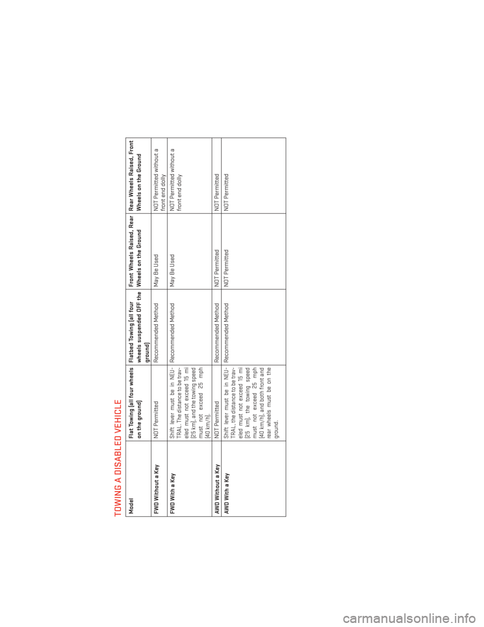
TOWING A DISABLED VEHICLEModelFlat Towing (all four wheels
on the ground) Flatbed Towing (all four
wheels suspended OFF the
ground)Front Wheels Raised, Rear
Wheels on the Ground
Rear Wheels Raised, Front
Wheels on the Ground
FWDWithoutaKey NOT Permitted
Recommended Method May Be Used NOT Permitted without a
front end dolly
FWDWithaKey
Shift lever must be in NEU-
TRAL. The distance to be trav-
eled must not exceed 15 mi
(25 km), and the towing speed
must not exceed 25 mph
(40 km/h).
Recommended Method May Be Used NOT Permitted without a
front end dolly
AWDWithoutaKey NOT Permitted
Recommended Method NOT Permitted NOT Permitted
AWDWithaKey
Shift lever must be in NEU-
TRAL, the distance to be trav-
eled must not exceed 15 mi
(25 km), the towing speed
must not exceed 25 mph
(40 km/h), and both front and
rear wheels must be on the
ground.
Recommended Method NOT Permitted NOT Permitted
WHAT TO DO IN EMERGENCIES
90
Page 93 of 124
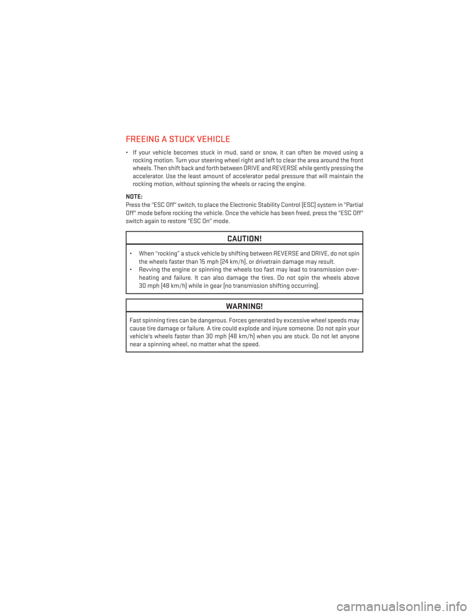
FREEING A STUCK VEHICLE
• If your vehicle becomes stuck in mud, sand or snow, it can often be moved using arocking motion. Turn your steering wheel right and left to clear the area around the front
wheels. Then shift back and forth between DRIVE and REVERSE while gently pressing the
accelerator. Use the least amount of accelerator pedal pressure that will maintain the
rocking motion, without spinning the wheels or racing the engine.
NOTE:
Press the "ESC Off" switch, to place the Electronic Stability Control (ESC) system in "Partial
Off" mode before rocking the vehicle. Once the vehicle has been freed, press the "ESC Off"
switch again to restore "ESC On" mode.
CAUTION!
• When “rocking” a stuck vehicle by shifting between REVERSE and DRIVE, do not spin the wheels faster than 15 mph (24 km/h), or drivetrain damage may result.
• Revving the engine or spinning the wheels too fast may lead to transmission over-
heating and failure. It can also damage the tires. Do not spin the wheels above
30 mph (48 km/h) while in gear (no transmission shifting occurring).
WARNING!
Fast spinning tires can be dangerous. Forces generated by excessive wheel speeds may
cause tire damage or failure. A tire could explode and injure someone. Do not spin your
vehicle's wheels faster than 30 mph (48 km/h) when you are stuck. Do not let anyone
near a spinning wheel, no matter what the speed.
WHAT TO DO IN EMERGENCIES
91
Page 99 of 124
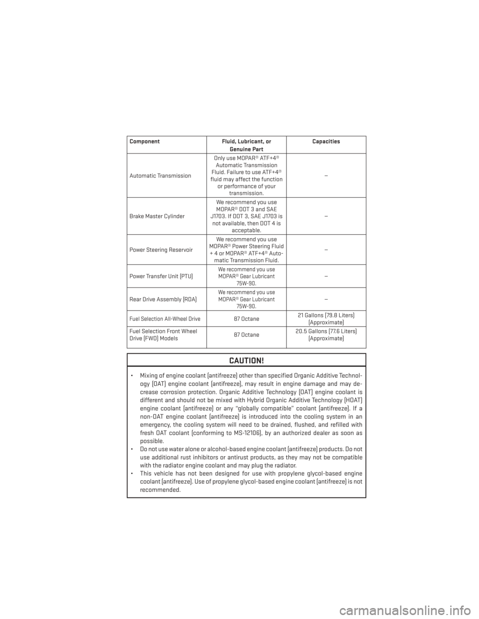
ComponentFluid, Lubricant, or
Genuine Part Capacities
Automatic Transmission Only use MOPAR® ATF+4®
Automatic Transmission
Fluid. Failure to use ATF+4®
fluid may affect the function or performance of your transmission. —
Brake Master Cylinder We recommend you use
MOPAR® DOT 3 and SAE
J1703. If DOT 3, SAE J1703 is not available, then DOT 4 is acceptable. —
Power Steering Reservoir We recommend you use
MOPAR® Power Steering Fluid + 4 or MOPAR® ATF+4® Auto- matic Transmission Fluid. —
Power Transfer Unit (PTU)
We recommend you use MOPAR® Gear Lubricant 75W-90.—
Rear Drive Assembly (RDA)
We recommend you use MOPAR® Gear Lubricant 75W-90.—
Fuel Selection All-Wheel Drive87 Octane 21 Gallons (79.8 Liters)
(Approximate)
Fuel Selection Front Wheel
Drive (FWD) Models 87 Octane20.5 Gallons (77.6 Liters)
(Approximate)
CAUTION!
• Mixing of engine coolant (antifreeze) other than specified Organic Additive Technol-
ogy (OAT) engine coolant (antifreeze), may result in engine damage and may de-
crease corrosion protection. Organic Additive Technology (OAT) engine coolant is
different and should not be mixed with Hybrid Organic Additive Technology (HOAT)
engine coolant (antifreeze) or any “globally compatible” coolant (antifreeze). If a
non-OAT engine coolant (antifreeze) is introduced into the cooling system in an
emergency, the cooling system will need to be drained, flushed, and refilled with
fresh OAT coolant (conforming to MS-12106), by an authorized dealer as soon as
possible.
• Do not use water alone or alcohol-based engine coolant (antifreeze) products. Do not
use additional rust inhibitors or antirust products, as they may not be compatible
with the radiator engine coolant and may plug the radiator.
• This vehicle has not been designed for use with propylene glycol-based engine
coolant (antifreeze). Use of propylene glycol-based engine coolant (antifreeze) is not
recommended.
MAINTAINING YOUR VEHICLE
97
Page 105 of 124
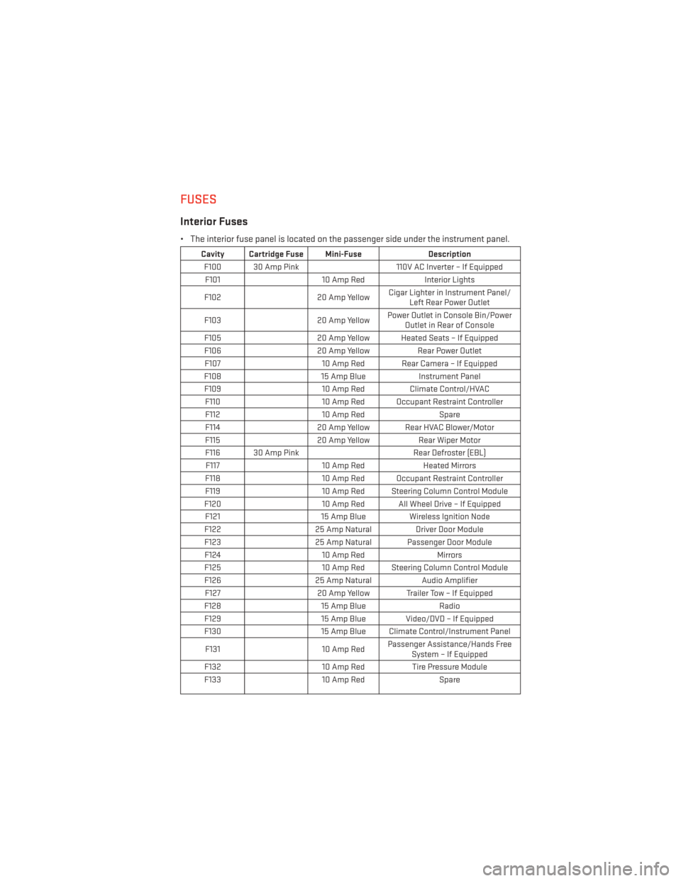
FUSES
Interior Fuses
• The interior fuse panel is located on the passenger side under the instrument panel.
Cavity Cartridge Fuse Mini-FuseDescription
F100 30 Amp Pink 110V AC Inverter – If Equipped
F101 10 Amp RedInterior Lights
F102 20 Amp YellowCigar Lighter in Instrument Panel/
Left Rear Power Outlet
F103 20 Amp YellowPower Outlet in Console Bin/Power
Outlet in Rear of Console
F105 20 Amp Yellow Heated Seats – If Equipped
F106 20 Amp YellowRear Power Outlet
F107 10 Amp Red Rear Camera – If Equipped
F108 15 Amp BlueInstrument Panel
F109 10 Amp RedClimate Control/HVAC
F110 10 Amp Red Occupant Restraint Controller
F112 10 Amp Red Spare
F114 20 Amp Yellow Rear HVAC Blower/Motor
F115 20 Amp YellowRear Wiper Motor
F116 30 Amp Pink Rear Defroster (EBL)
F117 10 Amp RedHeated Mirrors
F118 10 Amp Red Occupant Restraint Controller
F119 10 Amp Red Steering Column Control Module
F120 10 Amp Red All Wheel Drive – If Equipped
F121 15 Amp Blue Wireless Ignition Node
F122 25 Amp Natural Driver Door Module
F123 25 Amp Natural Passenger Door Module
F124 10 Amp RedMirrors
F125 10 Amp Red Steering Column Control Module
F126 25 Amp NaturalAudio Amplifier
F127 20 Amp Yellow Trailer Tow – If Equipped
F128 15 Amp Blue Radio
F129 15 Amp Blue Video/DVD – If Equipped
F130 15 Amp Blue Climate Control/Instrument Panel
F131 10 Amp RedPassenger Assistance/Hands Free
System – If Equipped
F132 10 Amp RedTire Pressure Module
F133 10 Amp RedSpare
MAINTAINING YOUR VEHICLE
103
Page 107 of 124
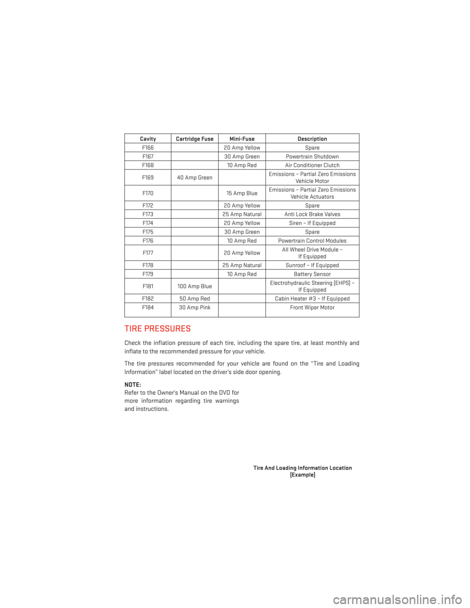
Cavity Cartridge Fuse Mini-FuseDescription
F166 20 Amp YellowSpare
F167 30 Amp Green Powertrain Shutdown
F168 10 Amp Red Air Conditioner Clutch
F169 40 Amp Green Emissions – Partial Zero Emissions
Vehicle Motor
F170 15 Amp BlueEmissions – Partial Zero Emissions
Vehicle Actuators
F172 20 Amp YellowSpare
F173 25 Amp Natural Anti Lock Brake Valves
F174 20 Amp Yellow Siren – If Equipped
F175 30 Amp GreenSpare
F176 10 Amp Red Powertrain Control Modules
F177 20 Amp YellowAll Wheel Drive Module –
If Equipped
F178 25 Amp Natural Sunroof – If Equipped
F179 10 Amp RedBattery Sensor
F181 100 Amp Blue Electrohydraulic Steering (EHPS) –
If Equipped
F182 50 Amp Red Cabin Heater #3 – If Equipped
F184 30 Amp Pink Front Wiper Motor
TIRE PRESSURES
Check the inflation pressure of each tire, including the spare tire, at least monthly and
inflate to the recommended pressure for your vehicle.
The tire pressures recommended for your vehicle are found on the “Tire and Loading
Information” label located on the driver’s side door opening.
NOTE:
Refer to the Owner's Manual on the DVD for
more information regarding tire warnings
and instructions.
Tire And Loading Information Location
(Example)
MAINTAINING YOUR VEHICLE
105
Page 108 of 124
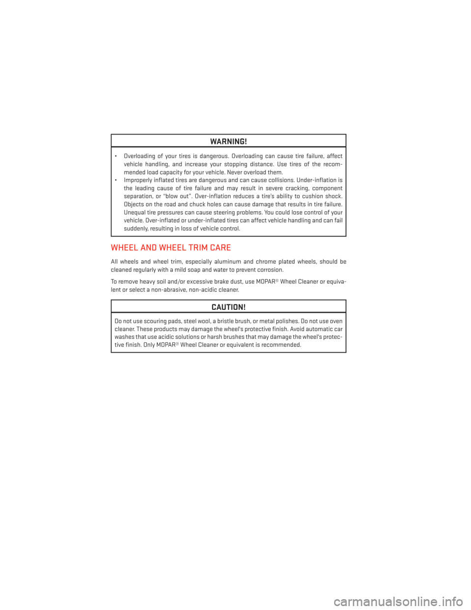
WARNING!
• Overloading of your tires is dangerous. Overloading can cause tire failure, affectvehicle handling, and increase your stopping distance. Use tires of the recom-
mended load capacity for your vehicle. Never overload them.
• Improperly inflated tires are dangerous and can cause collisions. Under-inflation is
the leading cause of tire failure and may result in severe cracking, component
separation, or “blow out”. Over-inflation reduces a tire’s ability to cushion shock.
Objects on the road and chuck holes can cause damage that results in tire failure.
Unequal tire pressures can cause steering problems. You could lose control of your
vehicle. Over-inflated or under-inflated tires can affect vehicle handling and can fail
suddenly, resulting in loss of vehicle control.
WHEEL AND WHEEL TRIM CARE
All wheels and wheel trim, especially aluminum and chrome plated wheels, should be
cleaned regularly with a mild soap and water to prevent corrosion.
To remove heavy soil and/or excessive brake dust, use MOPAR® Wheel Cleaner or equiva-
lent or select a non-abrasive, non-acidic cleaner.
CAUTION!
Do not use scouring pads, steel wool, a bristle brush, or metal polishes. Do not use oven
cleaner. These products may damage the wheel's protective finish. Avoid automatic car
washes that use acidic solutions or harsh brushes that may damage the wheel's protec-
tive finish. Only MOPAR® Wheel Cleaner or equivalent is recommended.
MAINTAINING YOUR VEHICLE
106