tow DODGE JOURNEY 2015 1.G Owners Manual
[x] Cancel search | Manufacturer: DODGE, Model Year: 2015, Model line: JOURNEY, Model: DODGE JOURNEY 2015 1.GPages: 648
Page 27 of 648
NOTE:Changes or modifications not expressly approved
by the party responsible for compliance could void the
user’s authority to operate the equipment.
If your RKE transmitter fails to operate from a normal
distance, check for these two conditions:
1. A weak battery in the transmitter. The expected life of
the battery is a minimum of three years.
2. Closeness to a radio transmitter such as a radio station
tower, airport transmitter, and some mobile or CB
radios.
REMOTE STARTING SYSTEM — IF EQUIPPED
This system uses the Remote Keyless Entry
(RKE) transmitter to start the engine conve-
niently from outside the vehicle while still
maintaining security. The system has a range of
approximately 300 ft (91 m).
NOTE:
•The vehicle must be equipped with an automatic
transmission to be equipped with Remote Start.
•Obstructions between the vehicle and the Key Fob may
reduce this range.
How To Use Remote Start
All of the following conditions must be met before the
engine will remote start:
•Shift lever in PARK
•Doors closed
•Hood closed
•Liftgate closed
•HAZARD switch off
•BRAKE switch inactive (brake pedal not pushed)
2
THINGS TO KNOW BEFORE STARTING YOUR VEHICLE 25
Page 45 of 648
For further information on Keyless Enter-N-Go™ (Pas-
sive Entry), refer to “Keyless Enter-N-Go™” in “Things
To Know Before Starting Your Vehicle”.
NOTE:The liftgate cannot be unlocked or locked with
the manual door lock plungers on the door trim panels or
the door lock cylinder on the driver’s door.
To open the unlocked liftgate, squeeze the handle and
pull the liftgate toward you. Gas props will raise and
support the liftgate in the open position.
NOTE:
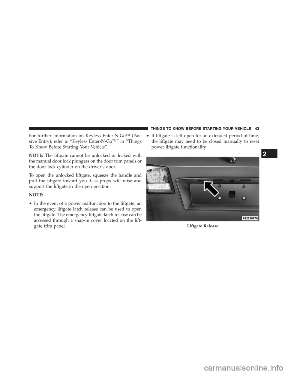
•In the event of a power malfunction to the liftgate, an
emergency liftgate latch release can be used to open
the liftgate. The emergency liftgate latch release can be
accessed through a snap-in cover located on the lift-
gate trim panel.
•If liftgate is left open for an extended period of time,
the liftgate may need to be closed manually to reset
power liftgate functionality.
Liftgate Release
2
THINGS TO KNOW BEFORE STARTING YOUR VEHICLE 43
Page 49 of 648
The outboard front passenger seat BeltAlert® is not
active when the outboard front passenger seat is unoc-
cupied. BeltAlert® may be triggered when an animal or
heavy object is on the outboard front passenger seat or
when the seat is folded flat (if equipped). It is recom-
mended that pets be restrained in the rear seat (if
equipped) in pet harnesses or pet carriers that are se-
cured by seat belts, and cargo is properly stowed.
BeltAlert® can be activated or deactivated by your au-
thorized dealer. Chrysler Group LLC does not recom-
mend deactivating BeltAlert®.
NOTE:If BeltAlert® has been deactivated, the Seat Belt
Reminder Light will continue to illuminate while the
driver ’s or outboard front passenger ’s (if equipped with
BeltAlert®) seat belt remains unbuckled.
Lap/Shoulder Belts
All seating positions in your vehicle are equipped with
lap/shoulder belts.
The seat belt webbing retractor will lock only during very
sudden stops or collisions. This feature allows the shoul-
der part of the seat belt to move freely with you under
normal conditions. However, in a collision the seat belt
will lock and reduce your risk of striking the inside of the
vehicle or being thrown out of the vehicle.
WARNING!
•Relying on the air bags alone could lead to more
severe injuries in a collision. The air bags work with
your seat belt to restrain you properly. In some
collisions, the air bags won’t deploy at all. Always
wear your seat belt even though you have air bags.
(Continued)
2
THINGS TO KNOW BEFORE STARTING YOUR VEHICLE 47
Page 54 of 648
stowed position. If necessary, slide the latch plate
down the webbing to allow the seat belt to retract
fully.
Lap/Shoulder Belt Untwisting Procedure
Use the following procedure to untwist a twisted lap/
shoulder belt.
1. Position the latch plate as close as possible to the
anchor point.
2. At about 6 to 12 in (15 to 30 cm) above the latch plate,
grasp and twist the seat belt webbing 180° to create a
fold that begins immediately above the latch plate.
3. Slide the latch plate upward over the folded webbing.
The folded webbing must enter the slot at the top of
the latch plate.
4. Continue to slide the latch plate up until it clears the
folded webbing and the seat belt is no longer twisted.
Adjustable Upper Shoulder Belt Anchorage
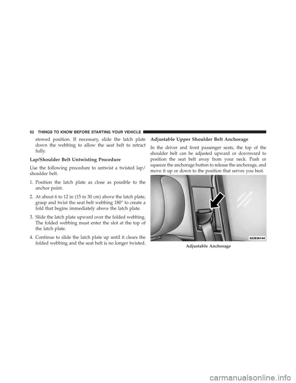
In the driver and front passenger seats, the top of the
shoulder belt can be adjusted upward or downward to
position the seat belt away from your neck. Push or
squeeze the anchorage button to release the anchorage, and
move it up or down to the position that serves you best.
Adjustable Anchorage
52 THINGS TO KNOW BEFORE STARTING YOUR VEHICLE
Page 62 of 648
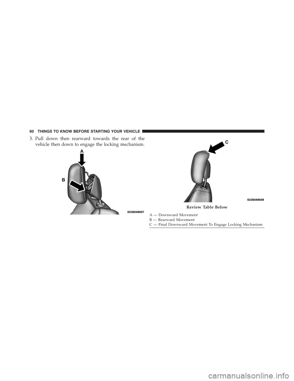
3. Pull down then rearward towards the rear of the
vehicle then down to engage the locking mechanism.
A— Downward MovementB—RearwardMovementC—FinalDownwardMovementToEngageLockingMechanism
Review Table Below
60 THINGS TO KNOW BEFORE STARTING YOUR VEHICLE
Page 95 of 648
center child restraint will block the seat belt buckle for
this position.
WARNING!
•Use anchorages B and C to install a LATCH-
compatible child restraint in the center seating
position (2). Do not install a LATCH-compatible
child restraint using anchorages C and D. This is
not a LATCH-compatible position in your vehicle.
•A child restraint installed in the center position (2)
will block the seat belt buckle for the empty right
outboard seating position (1). Do not use this seat
for another occupant.
•Never use the same lower anchorage to attach more
than one child restraint.
(Continued)
WARNING!(Continued)
•If you are installing three child restraints next to
each other, you must use the seat belt and the center
tether anchor for the center position. You can then
use either the LATCH anchors or the vehicle’s seat
belt for installing the child seats in the outboard
positions. Please refer to “Installing the LATCH-
Compatible Child Restraint System” for typical
installation instructions.
Always follow the directions of the child restraint manu-
facturer when installing your child restraint. Not all child
restraint systems will be installed as described here.
To Install A LATCH-Compatible Child Restraint
1. If the selected seating position has a Switchable Auto-
matic Locking Retractor (ALR) seat belt, stow the seat
belt following the instructions below. See the section
2
THINGS TO KNOW BEFORE STARTING YOUR VEHICLE 93
Page 96 of 648
“Installing Child Restraints Using the Vehicle Seat
Belt” to check what type of seat belt each seating
position has.
2. Loosen the adjusters on the lower straps and on the
tether strap of the child seat so that you can more
easily attach the hooks or connectors to the vehicle
anchorages.
3. Place the child seat between the lower anchorages for
that seating position. For some second row seats, you
may need to recline the seat and/or raise the head
restraint to get a better fit. If the rear seat can be moved
forward and rearward in the vehicle, you may wish to
move it to its rear-most position to make room for the
child seat. You may also move the front seat forward
to allow more room for the child seat.
4. Attach the lower hooks or connectors of the child
restraint to the lower anchorages in the selected seat-
ing position.
5. If the child restraint has a tether strap, connect it to the
top tether anchorage. See the section “Installing Child
Restraints Using the Top Tether Anchorage” for direc-
tions to attach a tether anchor.
6. Tighten all of the straps as you push the child restraint
rearward and downward into the seat. Remove slack
in the straps according to the child restraint manufac-
turer ’s instructions.
7. Test that the child restraint is installed tightly by
pulling back and forth on the child seat at the belt
path. It should not move more than 1 inch (25.4 mm)
in any direction.
How To Stow An Unused ALR Seatbelt:
When using the LATCH attaching system to install a
child restraint, stow all ALR seat belts that are not being
used by other occupants or being used to secure child
restraints. An unused belt could injure a child if they play
94 THINGS TO KNOW BEFORE STARTING YOUR VEHICLE
Page 116 of 648
▫Floor Console Storage..................275
▫Center Console Storage.................276
▫Flip ’n Stow™ Front Passenger Seat Storage —
If Equipped..........................278
▫Second-Row Passenger Seat Temporary Storage
Bin . . . . . . . . . . . . . . . . . . . . . . . . . . . . . . ..279
▫Second-Row Map Pocket And Grocery Retainers
— If Equipped.......................279
▫In-Floor Storage Bin With Removable Liner . . .279
!CARGO AREA FEATURES................280
▫Rechargeable Flashlight — If Equipped......280
▫Cargo Management System..............282
!REAR WINDOW FEATURES..............286
▫Rear Window Wiper/Washer.............286
▫Rear Window Defroster.................288
!ROOF LUGGAGE RACK — IF EQUIPPED . . . .289
11 4 U N D E R S TA N D I N G T H E F E AT U R E S O F Y O U R V E H I C L E
Page 117 of 648
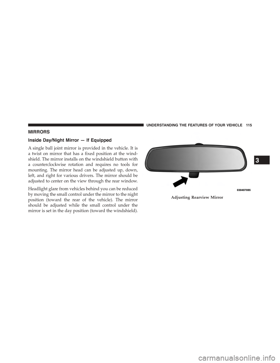
MIRRORS
Inside Day/Night Mirror — If Equipped
A single ball joint mirror is provided in the vehicle. It is
a twist on mirror that has a fixed position at the wind-
shield. The mirror installs on the windshield button with
a counterclockwise rotation and requires no tools for
mounting. The mirror head can be adjusted up, down,
left, and right for various drivers. The mirror should be
adjusted to center on the view through the rear window.
Headlight glare from vehicles behind you can be reduced
by moving the small control under the mirror to the night
position (toward the rear of the vehicle). The mirror
should be adjusted while the small control under the
mirror is set in the day position (toward the windshield).
Adjusting Rearview Mirror
3
UNDERSTANDING THE FEATURES OF YOUR VEHICLE 115
Page 122 of 648
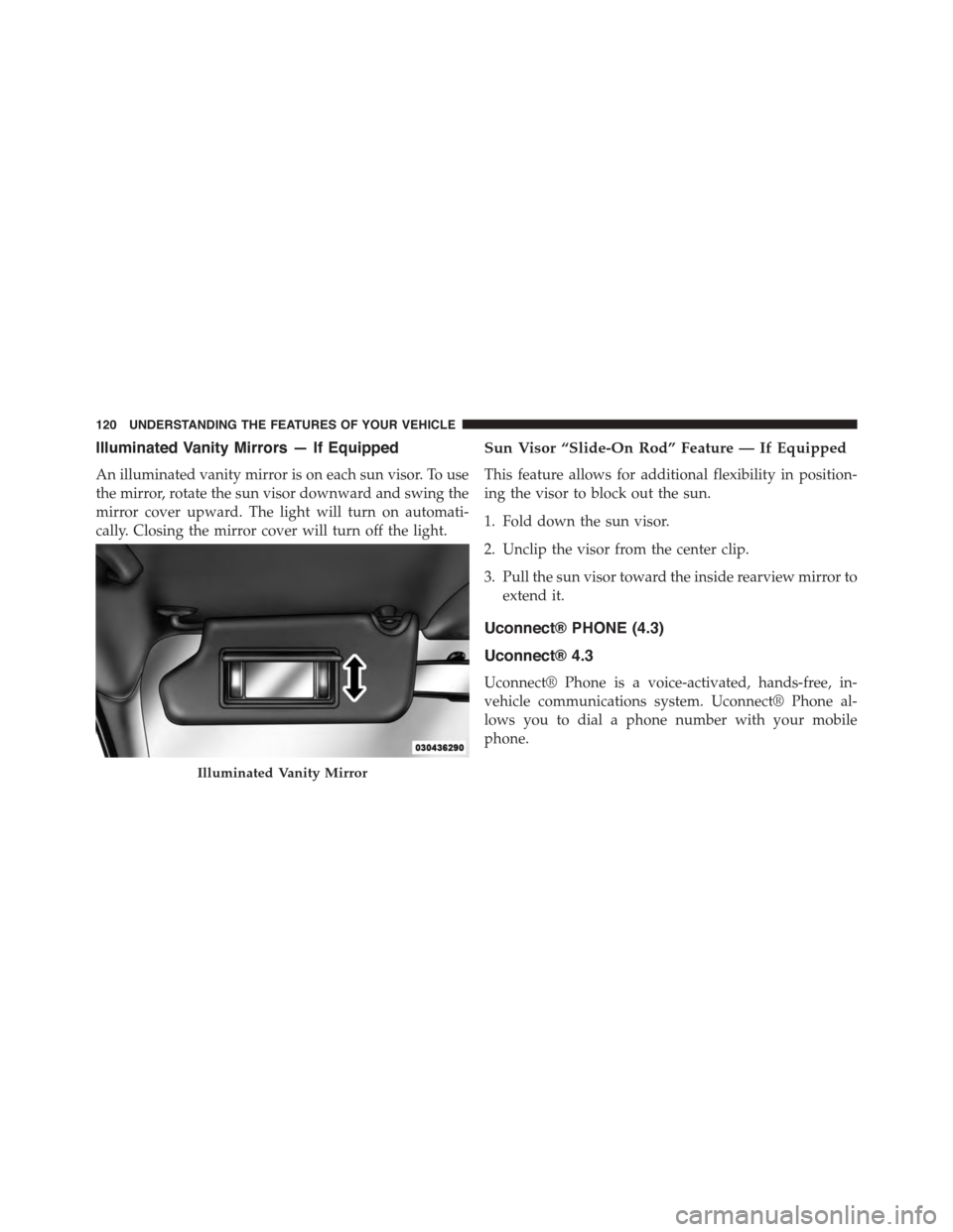
Illuminated Vanity Mirrors — If Equipped
An illuminated vanity mirror is on each sun visor. To use
the mirror, rotate the sun visor downward and swing the
mirror cover upward. The light will turn on automati-
cally. Closing the mirror cover will turn off the light.
Sun Visor “Slide-On Rod” Feature — If Equipped
This feature allows for additional flexibility in position-
ing the visor to block out the sun.
1. Fold down the sun visor.
2. Unclip the visor from the center clip.
3. Pull the sun visor toward the inside rearview mirror to
extend it.
Uconnect® PHONE (4.3)
Uconnect® 4.3
Uconnect® Phone is a voice-activated, hands-free, in-
vehicle communications system. Uconnect® Phone al-
lows you to dial a phone number with your mobile
phone.
Illuminated Vanity Mirror
120 UNDERSTANDING THE FEATURES OF YOUR VEHICLE