DODGE JOURNEY 2015 1.G Owners Manual
Manufacturer: DODGE, Model Year: 2015, Model line: JOURNEY, Model: DODGE JOURNEY 2015 1.GPages: 648
Page 291 of 648

NOTE:To prevent excessive battery drain, use the rear
window defroster only when the engine is operating.
CAUTION!
Failure to follow these cautions can cause damage to
the heating elements:
•Use care when washing the inside of the rear
window. Do not use abrasive window cleaners on
the interior surface of the window. Use a soft cloth
and a mild washing solution, wiping parallel to the
heating elements. Labels can be peeled off after
soaking with warm water.
•Do not use scrapers, sharp instruments, or abrasive
window cleaners on the interior surface of the
window.
•Keep all objects a safe distance from the window.
ROOF LUGGAGE RACK — IF EQUIPPED
The roof rack cross rails and side rails are designed to
carry cargo weight. The load must not exceed 150 lbs
(68 kg), and it should be distributed uniformly over the
cross rails. In addition, the roof rack does not increase the
total load carrying capacity of the vehicle. Be sure the
total load of cargo inside the vehicle plus that on the roof
rack does not exceed the maximum vehicle load capacity.
NOTE:The roof rack side rails on your vehicle are NOT
designed to carry a load without the addition of cross-
bars.
Metal crossbars are offered by MOPAR® accessories to
provide a functional roof rack system. See your autho-
rized dealer.
3
UNDERSTANDING THE FEATURES OF YOUR VEHICLE 289
Page 292 of 648
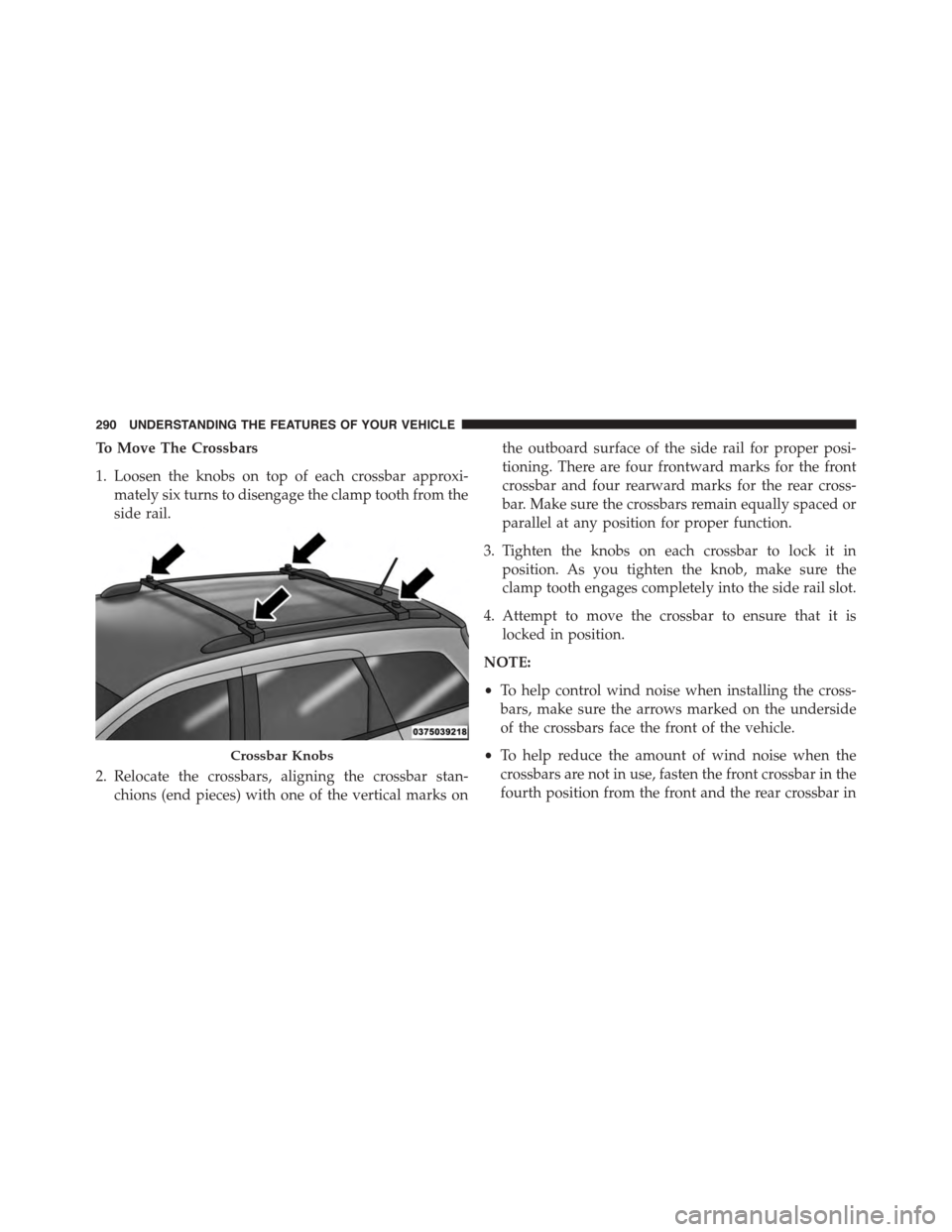
To Move The Crossbars
1. Loosen the knobs on top of each crossbar approxi-
mately six turns to disengage the clamp tooth from the
side rail.
2. Relocate the crossbars, aligning the crossbar stan-
chions (end pieces) with one of the vertical marks on
the outboard surface of the side rail for proper posi-
tioning. There are four frontward marks for the front
crossbar and four rearward marks for the rear cross-
bar. Make sure the crossbars remain equally spaced or
parallel at any position for proper function.
3. Tighten the knobs on each crossbar to lock it in
position. As you tighten the knob, make sure the
clamp tooth engages completely into the side rail slot.
4. Attempt to move the crossbar to ensure that it is
locked in position.
NOTE:
•To help control wind noise when installing the cross-
bars, make sure the arrows marked on the underside
of the crossbars face the front of the vehicle.
•To help reduce the amount of wind noise when the
crossbars are not in use, fasten the front crossbar in the
fourth position from the front and the rear crossbar in
Crossbar Knobs
290 UNDERSTANDING THE FEATURES OF YOUR VEHICLE
Page 293 of 648
the eighth position. The tie down holes on the crossbar
ends should always be used to tie down the load.
Check the straps frequently to be sure that the load
remains securely attached.
CAUTION!
•To prevent damage to the roof of your vehicle, DO
NOT carry any loads on the roof rack without the
crossbars installed. The load should be secured and
placed on top of the crossbars, not directly on the
roof. If it is necessary to place the load on the roof,
place a blanket or other protective layer between
the load and the roof surface.
•Crossbars should remain equally spaced or parallel
at any roof rack position for proper function. Non-
compliance could result in damage to the roof rack,
cargo, and vehicle.
(Continued)
CAUTION!(Continued)
•To avoid damage to the roof rack and vehicle, do
not exceed the maximum roof rack load capacity of
150 lb (68 kg). Always distribute heavy loads as
evenly as possible and secure the load appropri-
ately.
•Long loads, which extend over the windshield,
such as wood panels or surfboards, should be
secured to both the front and rear of the vehicle.
•Travel at reduced speeds and turn corners carefully
when carrying large or heavy loads on the roof
rack. Wind forces, due to natural causes or nearby
truck traffic, can add sudden upward loads. This is
especially true on large flat loads and may result in
damage to the cargo or your vehicle.
3
UNDERSTANDING THE FEATURES OF YOUR VEHICLE 291
Page 294 of 648
WARNING!
Cargo must be securely tied before driving your
vehicle. Improperly secured loads can fly off the
vehicle, particularly at high speeds, resulting in per-
sonal injury or property damage. Follow the roof rack
cautions when carrying cargo on your roof rack.
292 UNDERSTANDING THE FEATURES OF YOUR VEHICLE
Page 295 of 648
UNDERSTANDING YOUR INSTRUMENT PANEL
CONTENTS
!INSTRUMENT PANEL FEATURES..........296
!INSTRUMENT CLUSTER.................297
!INSTRUMENT CLUSTER DESCRIPTIONS.....298
!ELECTRONIC VEHICLE INFORMATION CENTER
(EVIC)..............................307
▫Electronic Vehicle Information Center (EVIC)
Displays............................309
▫EVIC White Indicators..................312
▫EVIC Amber Indicators.................312
▫EVIC Red Indicators...................313
▫Oil Change Due......................315
▫Fuel Economy........................316
▫Vehicle Speed........................318
▫Trip Info...........................318
▫Ti re P S I . . . . . . . . . . . . . . . . . . . . . . . . . . . ..319
▫Vehicle Info (Customer Information Features) . .319
▫Messages...........................320
▫Turn Menu OFF.......................320
!Uconnect® SETTINGS...................320
▫Buttons On The Faceplate................320
4
Page 296 of 648
▫Buttons On The Touchscreen..............320
▫Customer Programmable Features —
Uconnect® 4.3 Settings..................321
▫Customer Programmable Features —
Uconnect® System 8.4 Settings............333
!Uconnect® MULTIMEDIA — VIDEO
ENTERTAINMENT SYSTEM (VES™) — IF
EQUIPPED...........................347
▫Getting Started.......................348
▫Single Video Screen....................348
▫Play Video Games.....................349
▫Listen To An Audio Source On Channel 2 While A
Video Is Playing On Channel 1............350
▫Important Notes For Single Video Screen
System.............................351
▫Play A DVD Using The Touchscreen Radio . . .352
▫VES™ Remote Control — If Equipped.......353
▫Remote Control Storage.................356
▫Locking The Remote Control.............357
▫Replacing The Remote Control Batteries......357
▫Headphones Operation.................357
▫Replacing The Headphone Batteries.........358
▫Controls............................358
▫Unwired® Stereo Headphone Lifetime Limited
Warranty...........................359
▫System Information....................361
294 UNDERSTANDING YOUR INSTRUMENT PANEL
Page 297 of 648
!iPod®/USB/MP3 CONTROL..............370
!STEERING WHEEL AUDIO CONTROLS......370
▫Right-Hand Switch Functions.............371
▫Left-Hand Switch Functions For Radio
Operation...........................371
▫Left-Hand Switch Functions For Media (i.e., CD)
Operation..........................371
!CD/DVD DISC MAINTENANCE...........372
!RADIO OPERATION AND MOBILE PHONES . .372
!CLIMATE CONTROLS...................373
▫Manual Climate Controls With Touchscreen — If
Equipped...........................373
▫Rear Manual Temperature Control (MTC) — If
Equipped...........................381
▫Automatic Temperature Control (ATC) With
Touchscreen — If Equipped..............386
▫Rear Automatic Temperature Control (ATC) — If
Equipped...........................395
4
UNDERSTANDING YOUR INSTRUMENT PANEL 295
Page 298 of 648
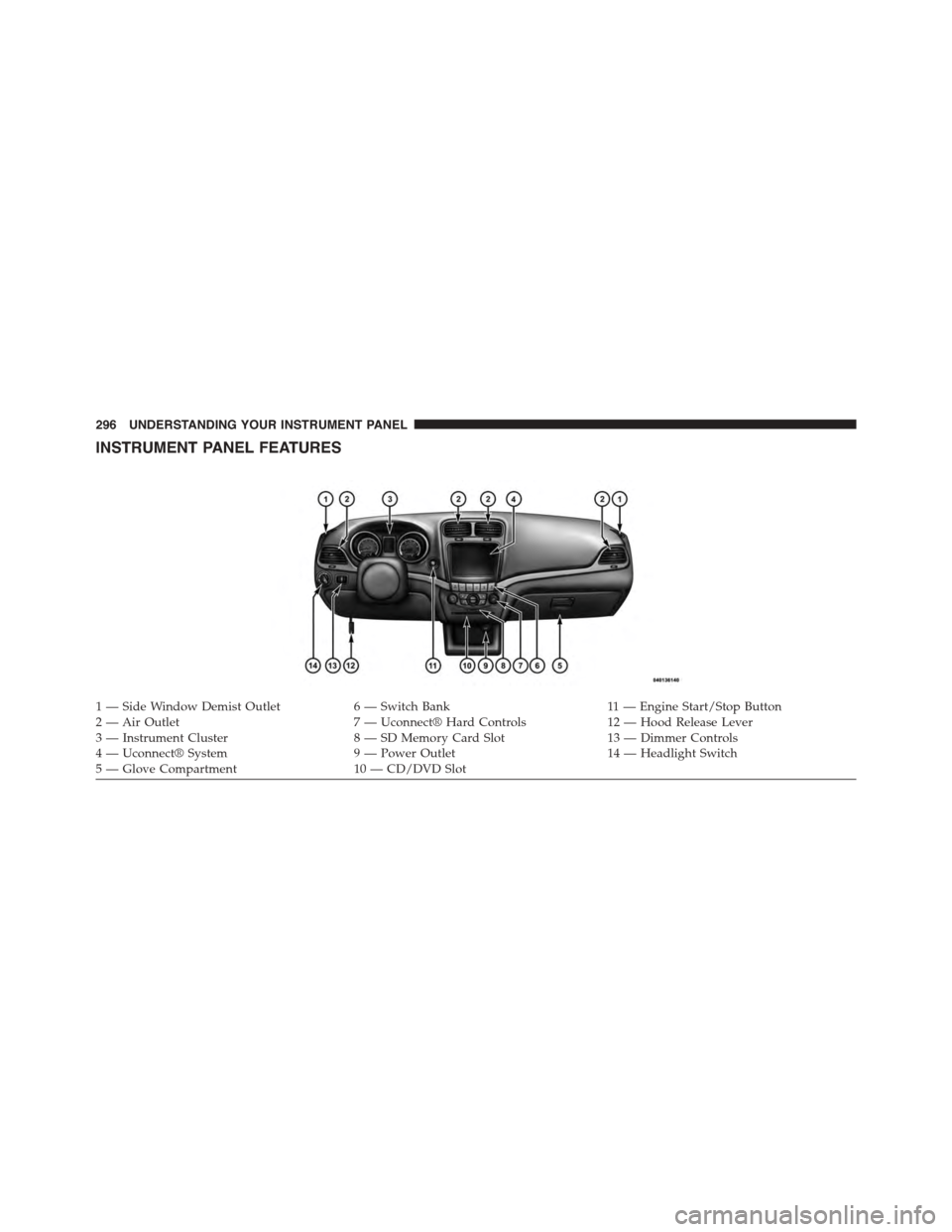
INSTRUMENT PANEL FEATURES
1—SideWindowDemistOutlet6—SwitchBank11 — E n g i n e S t a r t / S t o p B u t t o n2 — Air Outlet7 — Uconnect® Hard Controls12 — Hood Release Lever3 — Instrument Cluster8 — SD Memory Card Slot13 — Dimmer Controls4 — Uconnect® System9 — Power Outlet14 — Headlight Switch5—GloveCompartment10 — CD/DVD Slot
296 UNDERSTANDING YOUR INSTRUMENT PANEL
Page 299 of 648
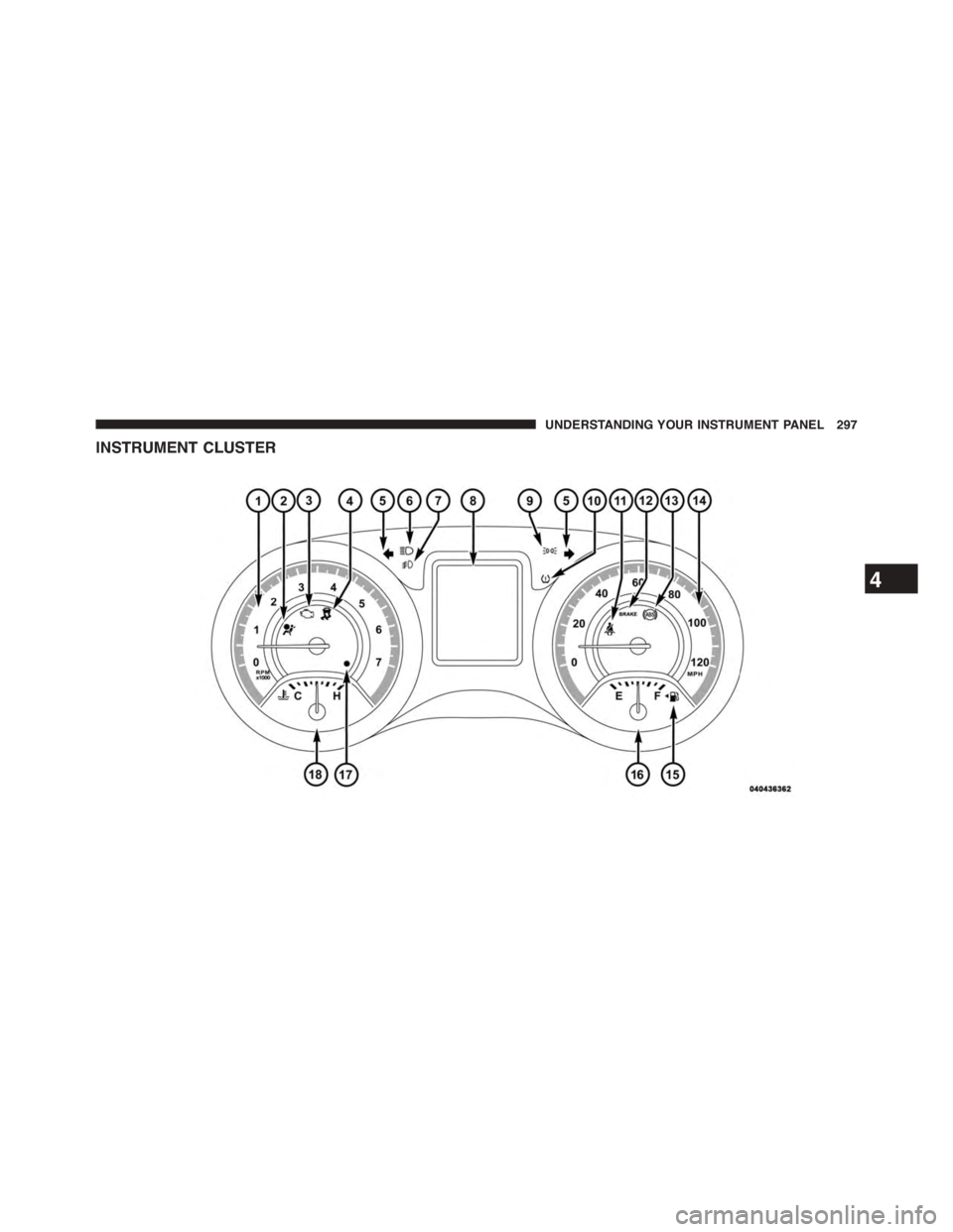
INSTRUMENT CLUSTER
4
UNDERSTANDING YOUR INSTRUMENT PANEL 297
Page 300 of 648
INSTRUMENT CLUSTER DESCRIPTIONS
1. Tachometer
This gauge measures engine revolutions per minute
(RPM x 1000). Before the pointer reaches the red area,
ease up on the accelerator to prevent engine damage.
2. Air Bag Warning Light
This light will turn on for four to eight seconds
as a bulb check when the ignition switch is first
turned to ON/RUN. If the light is either not on
during starting, stays on, or turns on while
driving, have the system inspected at an authorized
dealer as soon as possible. Refer to “Occupant Restraints”
in “Things To Know Before Starting Your Vehicle” for
further information.
3. Malfunction Indicator Light (MIL)
The Malfunction Indicator Light (MIL) is part of
an onboard diagnostic system, called OBD II, that
monitors engine and automatic transmission con-
trol systems. The light will illuminate when the key is in
the ON/RUN position, before engine start. If the bulb
does not come on when turning the key from OFF to
ON/RUN, have the condition checked promptly.
Certain conditions, such as a loose or missing gas cap,
poor fuel quality, etc., may illuminate the MIL after
engine start. The vehicle should be serviced if the light
stays on through several of your typical driving cycles. In
most situations, the vehicle will drive normally and will
not require towing.
298 UNDERSTANDING YOUR INSTRUMENT PANEL