warning light DODGE JOURNEY 2015 1.G Workshop Manual
[x] Cancel search | Manufacturer: DODGE, Model Year: 2015, Model line: JOURNEY, Model: DODGE JOURNEY 2015 1.GPages: 648
Page 482 of 648
the TPMS will update automatically. In addition, the
“Tire Pressure Monitoring Telltale Light” will turn off
and the graphic in the EVIC will display a new
pressure value instead of dashes (- -), as long as no tire
pressure is below the low-pressure warning limit in
any of the four active road tires. The vehicle may need
to be driven for up to 20 minutes above 15 mph
(24 km/h) in order for the TPMS to receive this
information.
General Information
This device complies with Part 15 of the FCC rules and
RSS 210 of Industry Canada. Operation is subject to the
following conditions:
•This device may not cause harmful interference.
•This device must accept any interference received,
including interference that may cause undesired op-
eration.
The tire pressure sensors are covered under one of the
following licenses:
United StatesMRXSSW4
Canada2546-SSW4
FUEL REQUIREMENTS
This engine is designed to meet all emis-
sions regulations and provide excellent
fuel economy and performance when us-
ing high-quality unleaded “regular” gaso-
line having an octane rating of 87. The use
of premium gasoline is not recommended, as it will not
provide any benefit over regular gasoline in these
engines.
Light spark knock at low engine speeds is not harmful to
your engine. However, continued heavy spark knock at
high speeds can cause damage and immediate service is
480 STARTING AND OPERATING
Page 492 of 648
WARNING!
•Never have any smoking materials lit in or near the
vehicle when the gas cap is removed or the tank is
being filled.
•Never add fuel to the vehicle when the engine is
running.
•A fire may result if gasoline is pumped into a
portable container that is inside of a vehicle. You
could be burned. Always place gas containers on
the ground while filling.
•Failure to follow this warning may result in serious
injury or death.
CAUTION!
•Damage to the fuel system or emissions control
system could result from using an improper fuel
tank filler tube cap (gas cap).
•A poorly fitting gas cap could let impurities into
the fuel system.
•A poorly fitting gas cap may cause the “Malfunc-
tion Indicator Light (MIL)” to turn on.
•To avoid fuel spillage and overfilling, do not “top
off” the fuel tank after filling. When the fuel
nozzle “clicks” or shuts off, the fuel tank is full.
NOTE:
•When the fuel nozzle “clicks” or shuts off, the fuel tank
is full.
•Tighten the gas cap until you hear a “clicking” sound.
This is an indication that the gas cap is tightened
490 STARTING AND OPERATING
Page 498 of 648
and trailer configuration/loading to comply with Gross
Axle Weight Rating (GAWR) requirements.
WARNING!
•An improperly adjusted Weight Distributing Hitch
system may reduce handling, stability, braking
performance, and could result in a collision.
•Weight Distributing Systems may not be compatible
with Surge Brake Couplers. Consult with your hitch
and trailer manufacturer or a reputable Recreational
Vehicle dealer for additional information.
Trailer Hitch Classification
The following chart provides the industry standard for
the maximum trailer weight a given trailer hitch class can
tow and should be used to assist you in selecting the
correct trailer hitch for your intended towing condition.
Trailer Hitch Classification Definitions
ClassMax. Trailer Hitch
Industry Standards
Class I - Light Duty 2,000 lbs (907 kg)
Class II - Medium Duty 3,500 lbs (1 587 kg)
Class III - Heavy Duty 5,000 lbs (2 268 kg)
Class IV - Extra Heavy
Duty
10,000 lbs (4 540 kg)
Refer to the “Trailer Towing Weights (Maximum
Trailer Weight Ratings)” chart for the Maximum
Gross Trailer Weight (GTW) towable for your given
drivetrain.
All trailer hitches should be professionally installed
on your vehicle.
496 STARTING AND OPERATING
Page 526 of 648
NOTE:
•For vehicles so equipped, do not attempt to install a
center cap or wheel cover on the compact spare.
•Refer to “Compact Spare Tire” and to “Limited-Use
Spare” under “Tires — General Information” in
“Starting and Operating” for additional warnings,
cautions, and information about the spare tire, its
use, and operation.
7. Install the wheel nuts with the cone-shaped end of the
nut toward the wheel. Lightly tighten the wheel nuts.
WARNING!
To avoid the risk of forcing the vehicle off the jack,
do not tighten the lug nuts fully until the vehicle has
been lowered. Failure to follow this warning may
result in personal injury.
8. Lower the vehicle by turning the jack screw counter-
clockwise with the jack handle.
9. Finish tightening the lug nuts. Push down on the
wrench while at the end of the handle for increased
leverage. Tighten the lug nuts in a star pattern until
each nut has been tightened twice. For the correct lug
nut torque refer to Torque Specifications in this sec-
tion. If in doubt about the correct tightness, have them
checked with a torque wrench by your authorized
dealer or service station.
10. Lower the jack to its fully closed position.
11. Place the deflated (flat) tire in the cargo area.Do not
stow the deflated tire in the spare tire stowage
location.Have the deflated (flat) tire repaired or
replaced as soon as possible.
524 WHAT TO DO IN EMERGENCIES
Page 527 of 648
12. To stow the winch cable and retainer, fit the as-
sembled jack-handle over the winch drive nut. Rotate
the jack-handle assembly clockwise until you hear
the winch mechanism click three times. It cannot be
over tightened.
13. Stow the jack-handle and jack. Remove the wheel
blocks from the vehicle and release the park brake.
14. Check the tire pressure as soon as possible. Adjust the
tire pressure as required.
Road Tire Installation
Vehicles Equipped With Wheel Covers
1. Mount the road tire on the axle.
2. To ease the installation process for steel wheels with
wheel covers, install two lug nuts on the mounting
studs which are on each side of the valve stem. Install
the lug nuts with the cone shaped end of the nut
toward the wheel. Lightly tighten the lug nuts.
WARNING!
To avoid the risk of forcing the vehicle off the jack,
do not tighten the lug nuts fully until the vehicle has
been lowered. Failure to follow this warning may
result in personal injury.
6
WHAT TO DO IN EMERGENCIES 525
Page 528 of 648
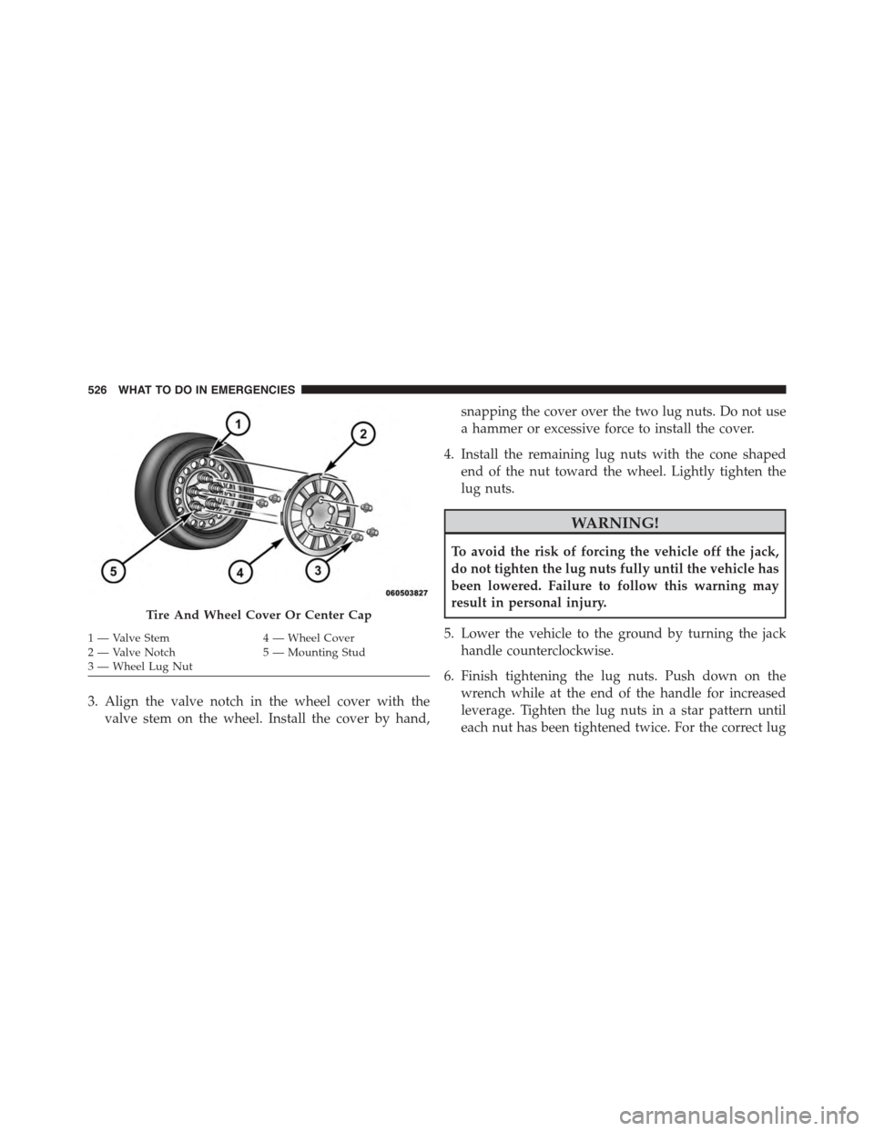
3. Align the valve notch in the wheel cover with the
valve stem on the wheel. Install the cover by hand,
snapping the cover over the two lug nuts. Do not use
a hammer or excessive force to install the cover.
4. Install the remaining lug nuts with the cone shaped
end of the nut toward the wheel. Lightly tighten the
lug nuts.
WARNING!
To avoid the risk of forcing the vehicle off the jack,
do not tighten the lug nuts fully until the vehicle has
been lowered. Failure to follow this warning may
result in personal injury.
5. Lower the vehicle to the ground by turning the jack
handle counterclockwise.
6. Finish tightening the lug nuts. Push down on the
wrench while at the end of the handle for increased
leverage. Tighten the lug nuts in a star pattern until
each nut has been tightened twice. For the correct lug
Tire And Wheel Cover Or Center Cap
1 — Valve Stem4 — Wheel Cover2—ValveNotch5—MountingStud3—WheelLugNut
526 WHAT TO DO IN EMERGENCIES
Page 529 of 648
nut torque refer to Torque Specifications in this sec-
tion. If in doubt about the correct tightness, have them
checked with a torque wrench by your authorized
dealer or service station.
7. After 25 miles (40 km) check the lug nut torque with a
torque wrench to ensure that all lug nuts are properly
seated against the wheel.
Vehicles Without Wheel Covers
1. Mount the road tire on the axle.
2. Install the remaining lug nuts with the cone shaped
end of the nut toward the wheel. Lightly tighten the
lug nuts.
WARNING!
To avoid the risk of forcing the vehicle off the jack,
do not tighten the lug nuts fully until the vehicle has
been lowered. Failure to follow this warning may
result in personal injury.
3. Lower the vehicle to the ground by turning the jack
handle counterclockwise.
4. Finish tightening the lug nuts. Push down on the
wrench while at the end of the handle for increased
leverage. Tighten the lug nuts in a star pattern until
each nut has been tightened twice. For proper lug nut
torque refer to Torque Specifications in this secton. If
in doubt about the correct tightness, have them
checked with a torque wrench by your authorized
dealer or service station.
6
WHAT TO DO IN EMERGENCIES 527
Page 530 of 648
5. After 25 miles (40 km) check the lug nut torque with a
torque wrench to ensure that all lug nuts are properly
seated against the wheel.
JUMP-STARTING
If your vehicle has a discharged battery it can be jump-
started using a set of jumper cables and a battery in
another vehicle or by using a portable battery booster
pack. Jump-starting can be dangerous if done improperly
so please follow the procedures in this section carefully.
WARNING!
Do not attempt jump-starting if the battery is frozen.
It could rupture or explode and cause personal injury.
CAUTION!
Do not use a portable battery booster pack or any
other booster source with a system voltage greater
than 12 Volts or damage to the battery, starter motor,
alternator or electrical system may occur.
NOTE:When using a portable battery booster pack
follow the manufacturer’s operating instructions and
precautions.
Preparations For Jump-Start
The battery in your vehicle is located between the left
front headlight assembly and the left front wheel splash
shield. To allow jump-starting, there are remote battery
posts located on the left side of the engine compartment.
528 WHAT TO DO IN EMERGENCIES
Page 570 of 648
WARNING!
Riding the brakes can lead to brake failure and
possibly a collision. Driving with your foot resting or
riding on the brake pedal can result in abnormally
high brake temperatures, excessive lining wear, and
possible brake damage. You would not have your full
braking capacity in an emergency.
Master Cylinder — Brake Fluid Level Check
Check the fluid level in the master cylinder immediately
if the “Brake Warning Light” indicates system failure.
Check the fluid level in the master cylinder when per-
forming underhood services.
Clean the top of the master cylinder area before removing
the cap. If necessary, add fluid to bring the fluid level up
to the requirements described on the brake fluid reser-
voir.
Overfilling of fluid is not recommended because it may
cause leaking in the system.
Fluid level can be expected to fall as the brake pads wear.
Brake fluid level should be checked when pads are
replaced. However, low fluid level may be caused by a
leak and a checkup may be needed.
Use only manufacturer’s recommended brake fluid. Re-
fer to “Fluids, Lubricants, and Genuine Parts” in “Main-
taining Your Vehicle” for further information.
568 MAINTAINING YOUR VEHICLE
Page 581 of 648
Cleaning Interior Trim
Interior Trim should be cleaned starting with a damp
cloth, a damp cloth with MOPAR® Total Clean or equiva-
lent, then MOPAR® Spot & Stain Remover or equivalent
if absolutely necessary. Do not use harsh cleaners or
Armor All®. Use MOPAR® Total Clean or equivalent to
clean vinyl upholstery.
Cleaning Leather Upholstery
MOPAR® Total Clean or equivalent is specifically recom-
mended for leather upholstery.
Your leather upholstery can be best preserved by regular
cleaning with a damp soft cloth. Small particles of dirt
can act as an abrasive and damage the leather upholstery
and should be removed promptly with a damp cloth.
Stubborn soils can be removed easily with a soft cloth
and MOPAR® Total Clean or equivalent. Care should be
taken to avoid soaking your leather upholstery with any
liquid. Please do not use polishes, oils, cleaning fluids,
solvents, detergents, or ammonia-based cleaners to clean
your leather upholstery. Application of a leather condi-
tioner is not required to maintain the original condition.
WARNING!
Do not use volatile solvents for cleaning purposes.
Many are potentially flammable, and if used in
closed areas they may cause respiratory harm.
Cleaning Headlights
Your vehicle is equipped with plastic headlights and fog
lights that are lighter and less susceptible to stone break-
age than glass headlights.
Plastic is not as scratch resistant as glass and therefore
different lens cleaning procedures must be followed.
7
MAINTAINING YOUR VEHICLE 579