brake light DODGE JOURNEY 2015 1.G User Guide
[x] Cancel search | Manufacturer: DODGE, Model Year: 2015, Model line: JOURNEY, Model: DODGE JOURNEY 2015 1.GPages: 140, PDF Size: 23.09 MB
Page 88 of 140
ROADSIDE ASSISTANCE
Dial toll-free 1-800-521-2779 for U.S. Residents or 1-800-363-4869 for Canadian
Residents.
•Provideyourname,vehicleidentificationnumber,licenseplatenumber,andyour
location, including the telephone number from which you are calling.
•Brieflydescribethenatureoftheproblemandanswerafewsimplequestions.
•Youwillbegiventhenameoftheserviceproviderandanestimatedtimeofarrival.If
you feel you are in an “unsafe situation”, please let us know. With your consent, we will
contact local police or safety authorities.
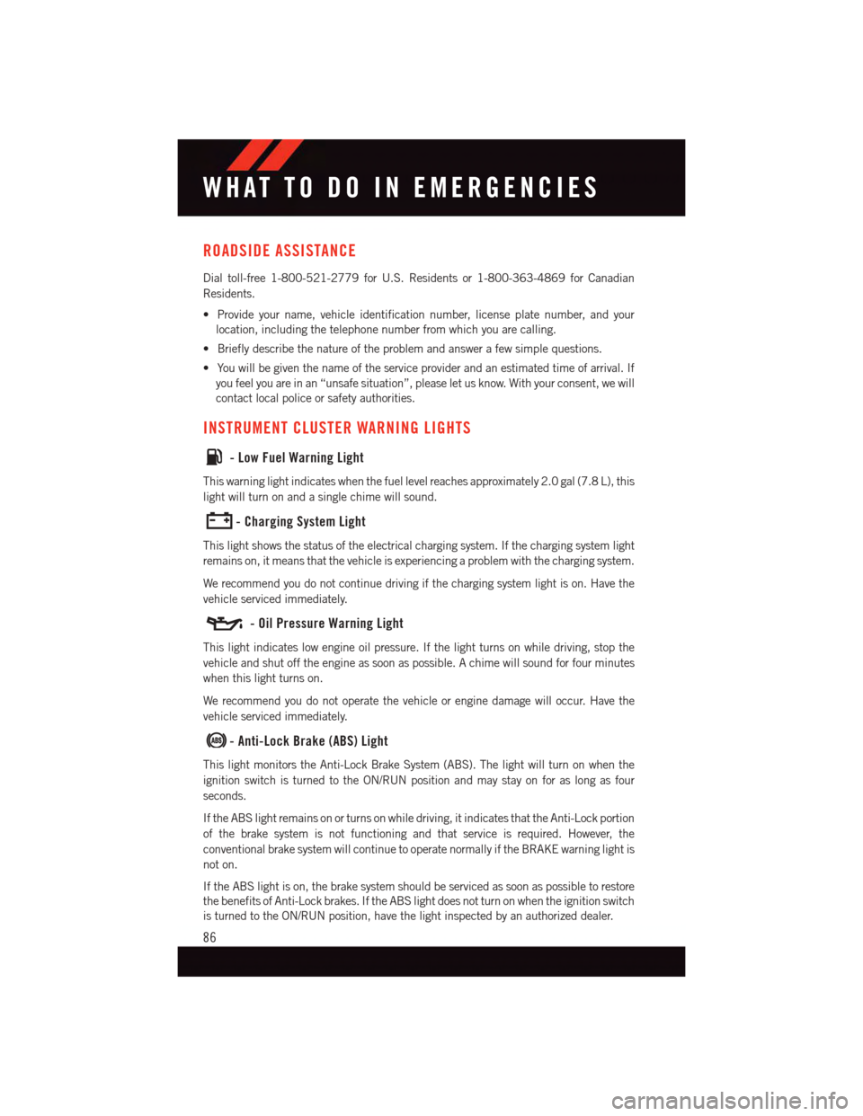
INSTRUMENT CLUSTER WARNING LIGHTS
-LowFuelWarningLight
This warning light indicates when the fuel level reaches approximately 2.0 gal (7.8 L), this
light will turn on and a single chime will sound.
-ChargingSystemLight
This light shows the status of the electrical charging system. If the charging system light
remains on, it means that the vehicle is experiencing a problem with the charging system.
We recommend you do not continue driving if the charging system light is on. Have the
vehicle serviced immediately.
-OilPressureWarningLight
This light indicates low engine oil pressure. If the light turns on while driving, stop the
vehicle and shut off the engine as soon as possible. A chime will sound for four minutes
when this light turns on.
We recommend you do not operate the vehicle or engine damage will occur. Have the
vehicle serviced immediately.
-Anti-LockBrake(ABS)Light
This light monitors the Anti-Lock Brake System (ABS). The light will turn on when the
ignition switch is turned to the ON/RUN position and may stay on for as long as four
seconds.
If the ABS light remains on or turns on while driving, it indicates that the Anti-Lock portion
of the brake system is not functioning and that service is required. However, the
conventional brake system will continue to operate normally if the BRAKE warning light is
not on.
If the ABS light is on, the brake system should be serviced as soon as possible to restore
the benefits of Anti-Lock brakes. If the ABS light does not turn on when the ignition switch
is turned to the ON/RUN position, have the light inspected by an authorized dealer.
WHAT TO DO IN EMERGENCIES
86
Page 91 of 140
WARNING!
Ahotenginecoolingsystemisdangerous.Youorotherscouldbebadlyburnedby
steam or boiling coolant.
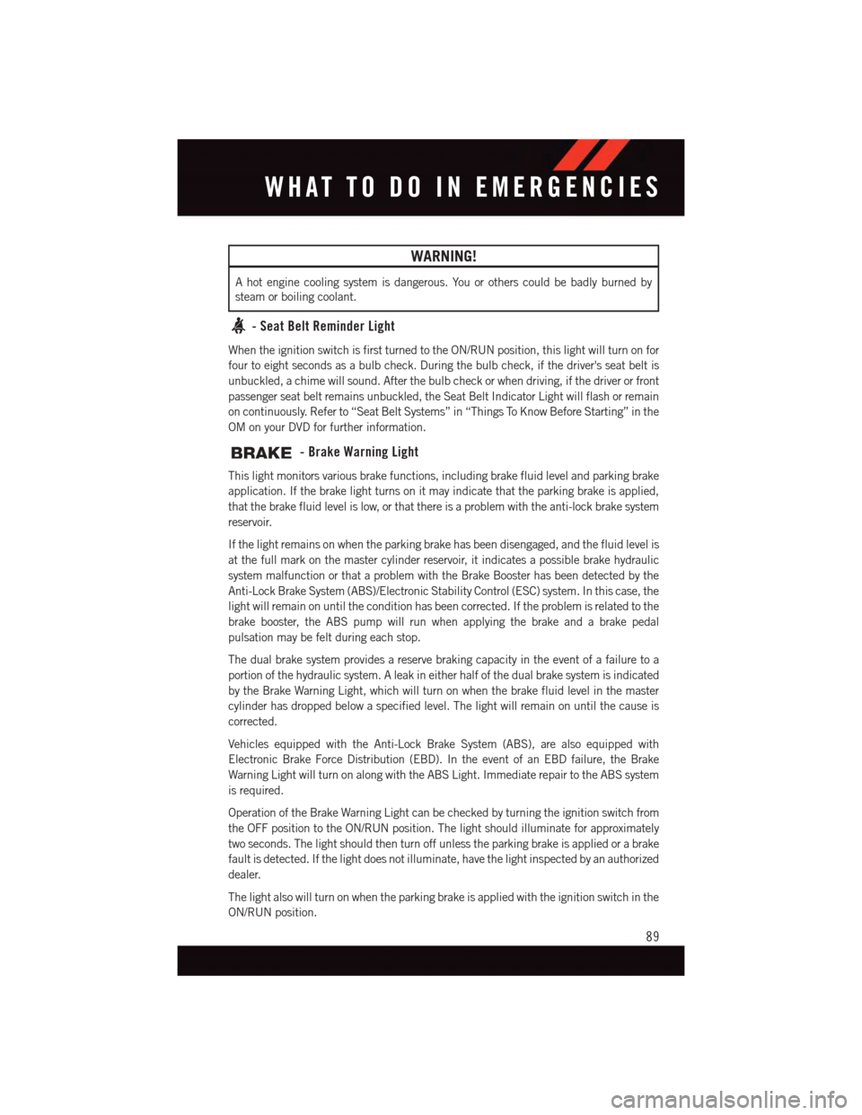
-SeatBeltReminderLight
When the ignition switch is first turned to the ON/RUN position, this light will turn on for
four to eight seconds as a bulb check. During the bulb check, if the driver's seat belt is
unbuckled, a chime will sound. After the bulb check or when driving, if the driver or front
passenger seat belt remains unbuckled, the Seat Belt Indicator Light will flash or remain
on continuously. Refer to “Seat Belt Systems” in “Things To Know Before Starting” in the
OM on your DVD for further information.
-BrakeWarningLight
This light monitors various brake functions, including brake fluid level and parking brake
application. If the brake light turns on it may indicate that the parking brake is applied,
that the brake fluid level is low, or that there is a problem with the anti-lock brake system
reservoir.
If the light remains on when the parking brake has been disengaged, and the fluid level is
at the full mark on the master cylinder reservoir, it indicates a possible brake hydraulic
system malfunction or that a problem with the Brake Booster has been detected by the
Anti-Lock Brake System (ABS)/Electronic Stability Control (ESC) system. In this case, the
light will remain on until the condition has been corrected. If the problem is related to the
brake booster, the ABS pump will run when applying the brake and a brake pedal
pulsation may be felt during each stop.
The dual brake system provides a reserve braking capacity in the event of a failure to a
portion of the hydraulic system. A leak in either half of the dual brake system is indicated
by the Brake Warning Light, which will turn on when the brake fluid level in the master
cylinder has dropped below a specified level. The light will remain on until the cause is
corrected.
Vehicles equipped with the Anti-Lock Brake System (ABS), are also equipped with
Electronic Brake Force Distribution (EBD). In the event of an EBD failure, the Brake
Warning Light will turn on along with the ABS Light. Immediate repair to the ABS system
is required.
Operation of the Brake Warning Light can be checked by turning the ignition switch from
the OFF position to the ON/RUN position. The light should illuminate for approximately
two seconds. The light should then turn off unless the parking brake is applied or a brake
fault is detected. If the light does not illuminate, have the light inspected by an authorized
dealer.
The light also will turn on when the parking brake is applied with the ignition switch in the
ON/RUN position.
WHAT TO DO IN EMERGENCIES
89
Page 92 of 140
NOTE:
This light shows only that the parking brake is applied. It does not show the degree of
brake application.
WARNING!
Driving a vehicle with the red brake light on is dangerous. Part of the brake system may
have failed. It will take longer to stop the vehicle. You could have a collision. Have the
vehicle checked immediately.
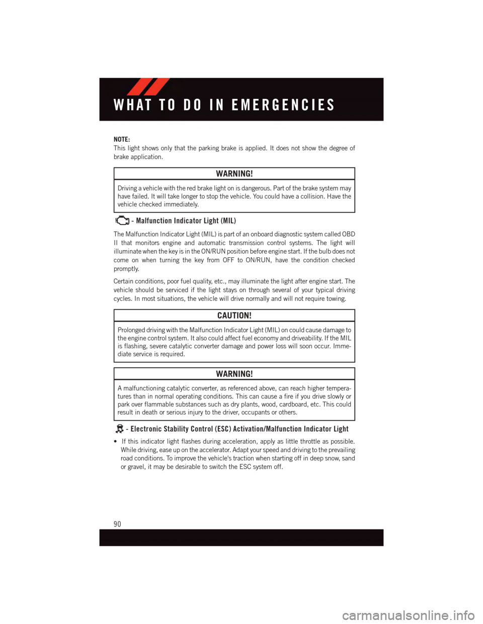
-MalfunctionIndicatorLight(MIL)
The Malfunction Indicator Light (MIL) is part of an onboard diagnostic system called OBD
II that monitors engine and automatic transmission control systems. The light will
illuminate when the key is in the ON/RUN position before engine start. If the bulb does not
come on when turning the key from OFF to ON/RUN, have the condition checked
promptly.
Certain conditions, poor fuel quality, etc., may illuminate the light after engine start. The
vehicle should be serviced if the light stays on through several of your typical driving
cycles. In most situations, the vehicle will drive normally and will not require towing.
CAUTION!
Prolonged driving with the Malfunction Indicator Light (MIL) on could cause damage to
the engine control system. It also could affect fuel economy and driveability. If the MIL
is flashing, severe catalytic converter damage and power loss will soon occur. Imme-
diate service is required.
WARNING!
Amalfunctioningcatalyticconverter,asreferencedabove,canreachhighertempera-
tures than in normal operating conditions. This can cause a fire if you drive slowly or
park over flammable substances such as dry plants, wood, cardboard, etc. This could
result in death or serious injury to the driver, occupants or others.
-ElectronicStabilityControl(ESC)Activation/MalfunctionIndicatorLight
•Ifthisindicatorlightflashesduringacceleration,applyaslittlethrottleaspossible.
While driving, ease up on the accelerator. Adapt your speed and driving to the prevailing
road conditions. To improve the vehicle's traction when starting off in deep snow, sand
or gravel, it may be desirable to switch the ESC system off.
WHAT TO DO IN EMERGENCIES
90
Page 94 of 140
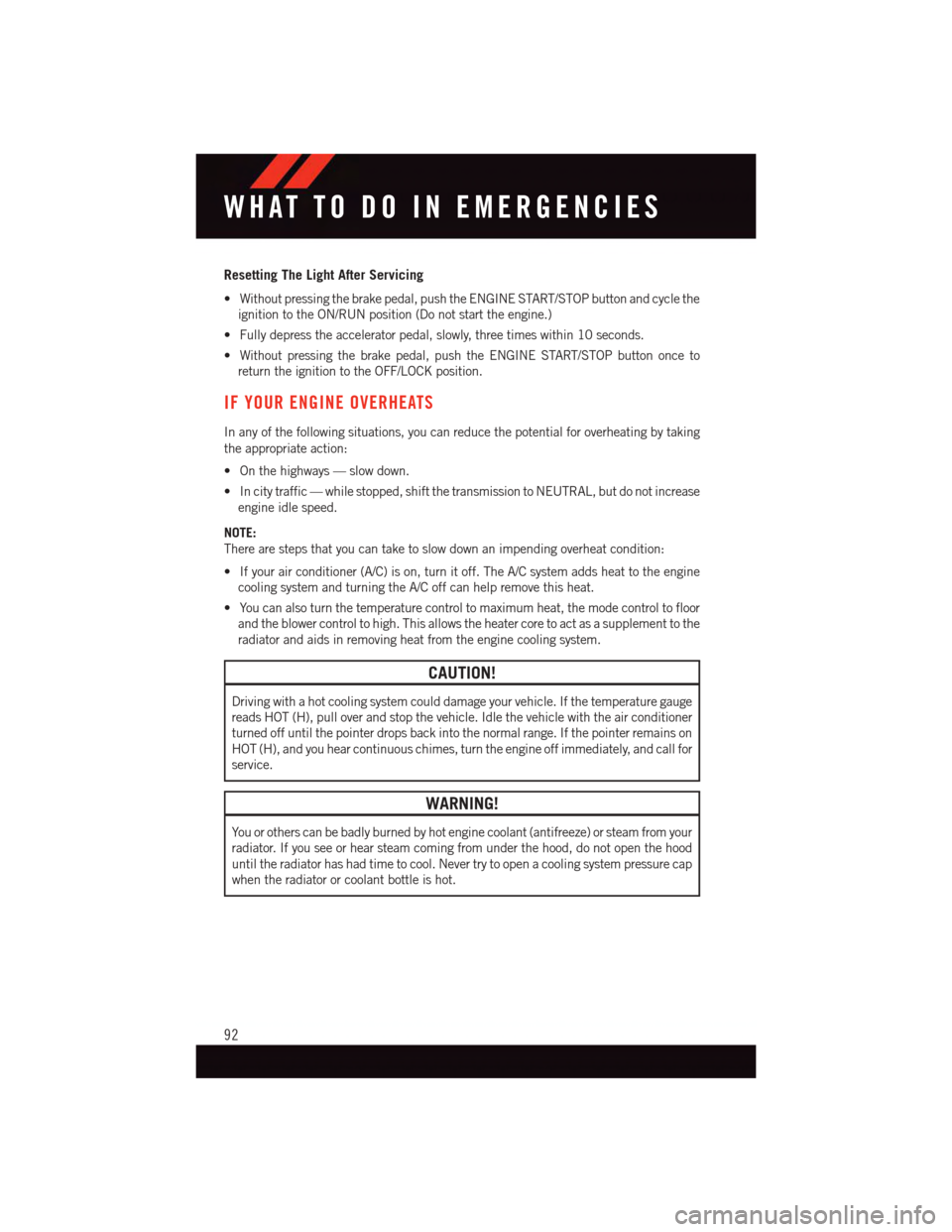
Resetting The Light After Servicing
•Withoutpressingthebrakepedal,pushtheENGINESTART/STOPbuttonandcyclethe
ignition to the ON/RUN position (Do not start the engine.)
•Fullydepresstheacceleratorpedal,slowly,threetimeswithin10seconds.
•Withoutpressingthebrakepedal,pushtheENGINESTART/STOPbuttononceto
return the ignition to the OFF/LOCK position.
IF YOUR ENGINE OVERHEATS
In any of the following situations, you can reduce the potential for overheating by taking
the appropriate action:
•Onthehighways—slowdown.
•Incitytraffic—whilestopped,shiftthetransmissiontoNEUTRAL,butdonotincrease
engine idle speed.
NOTE:
There are steps that you can take to slow down an impending overheat condition:
•Ifyourairconditioner(A/C)ison,turnitoff.TheA/Csystemaddsheattotheengine
cooling system and turning the A/C off can help remove this heat.
•Youcanalsoturnthetemperaturecontroltomaximumheat,themodecontroltofloor
and the blower control to high. This allows the heater core to act as a supplement to the
radiator and aids in removing heat from the engine cooling system.
CAUTION!
Driving with a hot cooling system could damage your vehicle. If the temperature gauge
reads HOT (H), pull over and stop the vehicle. Idle the vehicle with the air conditioner
turned off until the pointer drops back into the normal range. If the pointer remains on
HOT (H), and you hear continuous chimes, turn the engine off immediately, and call for
service.
WARNING!
Yo u o r o t h e r s c a n b e b a d l y b u r n e d b y h o t e n g i n e c o o l a n t ( a n t i f r e e z e ) o r s t e a m f r o m y o u r
radiator. If you see or hear steam coming from under the hood, do not open the hood
until the radiator has had time to cool. Never try to open a cooling system pressure cap
when the radiator or coolant bottle is hot.
WHAT TO DO IN EMERGENCIES
92
Page 103 of 140
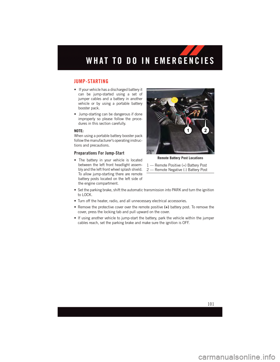
JUMP-STARTING
•Ifyourvehiclehasadischargedbatteryit
can be jump-started using a set of
jumper cables and a battery in another
vehicle or by using a portable battery
booster pack.
•Jump-startingcanbedangerousifdone
improperly so please follow the proce-
dures in this section carefully.
NOTE:
When using a portable battery booster pack
follow the manufacturer's operating instruc-
tions and precautions.
Preparations For Jump-Start
•Thebatteryinyourvehicleislocated
between the left front headlight assem-
bly and the left front wheel splash shield.
To a l l o w j u m p - s t a r t i n g t h e r e a r e r e m o t e
battery posts located on the left side of
the engine compartment.
•Settheparkingbrake,shifttheautomatictransmissionintoPARKandturntheignition
to LOCK.
•Turnofftheheater,radio,andallunnecessaryelectricalaccessories.
•Removetheprotectivecoverovertheremotepositive(+)battery post. To remove the
cover, press the locking tab and pull upward on the cover.
•Ifusinganothervehicletojump-startthebattery,parkthevehiclewithinthejumper
cables reach, set the parking brake and make sure the ignition is OFF.
Remote Battery Post Locations
1—RemotePositive(+)BatteryPost2—RemoteNegative(-)BatteryPost
WHAT TO DO IN EMERGENCIES
101
Page 117 of 140
Yo u r a u t h o r i z e d d e a l e r w i l l r e s e t t h e o i l c h a n g e i n d i c a t o r m e s s a g e a f t e r c o m p l e t i n g t h e
scheduled oil change. If a scheduled oil change is performed by someone other than your
authorized dealer, the message can be reset by referring to the steps described under
“Instrument Cluster Warning Lights” in “What To Do In Emergencies” in this guide or
“Electronic Vehicle Information Center (EVIC)” in “Understanding Your Instrument
Panel” in your Owners Manual on the DVD for further information.
NOTE:
Under no circumstances should oil change intervals exceed 10,000 miles (16,000 km)
or twelve months, whichever comes first.
Severe Duty All Models
Change Engine Oil at 4000 miles (6,500 km) if the vehicle is operated in a dusty and off
road environment. This type of vehicle use is considered Severe Duty.
Once A Month Or Before A Long Trip:
•Checkengineoillevel.
•Checkwindshieldwasherfluidlevel.
•Checktirepressureandlookforunusualwearordamage.Rotatetiresatthefirstsign
of irregular wear, even if it occurs before the oil indicator system turns on.
•Checkthefluidlevelsofthecoolantreservoir,brakemastercylinder,powersteering
and transmission (4-speed only) and fill as needed.
•Checkfunctionofallinteriorandexteriorlights.
Required Maintenance Intervals.
Refer to the Maintenance Schedules on the following page for the required maintenance
intervals.
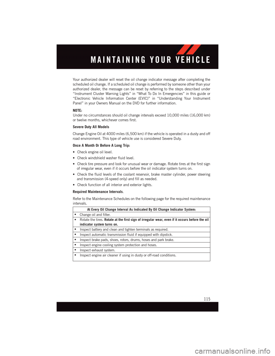
At Every Oil Change Interval As Indicated By Oil Change Indicator System:
•Change oil and filter.
•Rotatethetires.Rotate at the first sign of irregular wear, even if it occurs before the oil
indicator system turns on.
•Inspect battery and clean and tighten terminals as required.
•Inspect automatic transmission fluid if equipped with dipstick.
•Inspect brake pads, shoes, rotors, drums, hoses and park brake.
•Inspect engine cooling system protection and hoses.
•Inspect exhaust system.
•Inspect engine air cleaner if using in dusty or off-road conditions.
MAINTAINING YOUR VEHICLE
115
Page 122 of 140
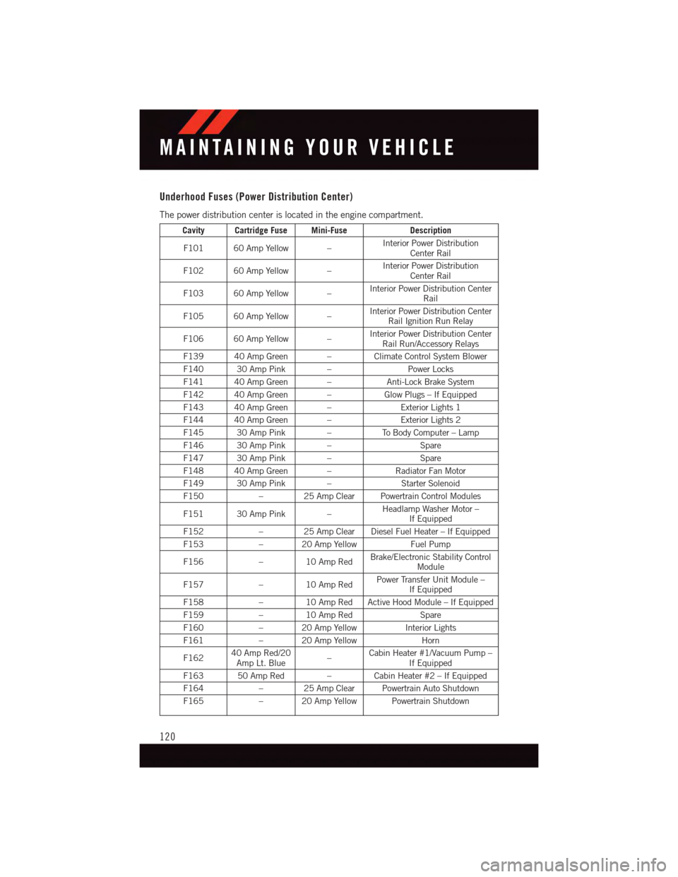
Underhood Fuses (Power Distribution Center)
The power distribution center is located in the engine compartment.
Cavity Cartridge Fuse Mini-FuseDescription
F101 60 Amp Yellow –Interior Power DistributionCenter Rail
F102 60 Amp Yellow –Interior Power DistributionCenter Rail
F103 60 Amp Yellow –Interior Power Distribution CenterRail
F105 60 Amp Yellow –Interior Power Distribution CenterRail Ignition Run Relay
F106 60 Amp Yellow –Interior Power Distribution CenterRail Run/Accessory Relays
F139 40 Amp Green – Climate Control System Blower
F140 30 Amp Pink –Power Locks
F141 40 Amp Green –Anti-Lock Brake System
F142 40 Amp Green –Glow Plugs – If Equipped
F143 40 Amp Green –Exterior Lights 1
F144 40 Amp Green –Exterior Lights 2
F145 30 Amp Pink –To B o d y C o m p u t e r – L a m p
F146 30 Amp Pink –Spare
F147 30 Amp Pink –Spare
F148 40 Amp Green –Radiator Fan Motor
F149 30 Amp Pink –Starter Solenoid
F150–25AmpClearPowertrainControlModules
F151 30 Amp Pink –Headlamp Washer Motor –If Equipped
F152–25AmpClearDieselFuelHeater–IfEquipped
F153–20AmpYellowFuel Pump
F156–10AmpRedBrake/Electronic Stability ControlModule
F157–10AmpRedPower Transfer Unit Module –If Equipped
F158–10AmpRedActiveHoodModule–IfEquipped
F159–10AmpRedSpare
F160–20AmpYellowInterior Lights
F161–20AmpYellowHorn
F16240 Amp Red/20Amp Lt. Blue–Cabin Heater #1/Vacuum Pump –If Equipped
F163 50 Amp Red – Cabin Heater #2 – If Equipped
F164–25AmpClearPowertrainAutoShutdown
F165–20AmpYellowPowertrainShutdown
MAINTAINING YOUR VEHICLE
120
Page 132 of 140
Adding Engine Coolant (Antifreeze) . .114
Adding Washer Fluid..........114
Air Bag
Advance Front Air Bag.......16
Air Bags . . . . . . . . . . . . . . .16
Air Bag Warning Light . . . . .16, 87
Front Air Bag . . . . . . . . . . . .16
Rollover . . . . . . . . . . . . . . .16
Side Impacts.............16
Air Cleaner, Engine (Engine Air Cleaner
Filter)................114Air Conditioner Maintenance.....114Air Conditioning.............40Air Conditioning Refrigerant......114Air Conditioning System........114AlarmVehicle Security Alarm.......14Alarm (Security Alarm).......14,91Antifreeze (Engine Coolant) . . .112, 114Disposal . . . . . . . . . . . . . .114Anti-Lock Brake System (ABS).....86Appearance Care............114Arming System (Security Alarm)....14Assistance Towing............86Automatic Headlights..........37Automatic Oil Change Indicator.....91
Automatic Temperature Control (ATC)..40Automatic TransmissionAdding Fluid............114Fluid Type . . . . . . . . . . . . .114
Back-Up Camera............43Battery.................114Charging System Light.......86Body Mechanism Lubrication.....114Brake Fluid . . . . . . . . . . . . . . .114Brakes . . . . . . . . . . . . . . . . .114Brake System.............114Fluid Check............114Master Cylinder..........114Warning Light . . . . . . . . . . . .89Break-In Recommendations, NewVehicle . . . . . . . . . . . . . . . .35Bulb Replacement...........124Bulbs, Light . . . . . . . . . . . . . .124
Calibration, Compass..........77Capacities, Fluid............112
Caps, FillerOil (Engine)............114Car Washes . . . . . . . . . . . . . . .114Changing A Flat Tire...........93Charging System Light.........86Check Engine Light (MalfunctionIndicator Light) . . . . . . . . . . . .90Child Restraint..............19CleaningWheels...............114Windshield Wiper Blades.....114Climate Control . . . . . . . . . . . . .40Cluster Warning/Indicator LightsAir Bag Warning Light . . . . . . .87Brake Warning Light . . . . . . . . .89Electronic Speed Control ONIndicator . . . . . . . . . . . . . . .91Electronic Speed Control SETIndicator . . . . . . . . . . . . . . .91Front Fog Light Indicator . . . . . .91High Beam Indicator........91Tu r n S i g n a l I n d i c a t o r........91Vehicle Security Light........91Clutch . . . . . . . . . . . . . . . . .114Clutch Fluid . . . . . . . . . . . . . .114Compact Spare Tire..........122Compass Calibration...........77Cooling System . . . . . . . . . . . . .114Adding Coolant (Antifreeze)....114Coolant Capacity.........112Coolant Level...........114Disposal of Used Coolant.....114Drain, Flush, and Refill......114Inspection . . . . . . . . . . . . .114Points to Remember.......114Pressure Cap . . . . . . . . . . .114Selection of Coolant(Antifreeze).........112, 114Corrosion Protection . . . . . . . . . .114Cruise Control (Speed Control).....38Cruise Light . . . . . . . . . . . . . . .38Customer Assistance..........126Customer ProgrammableFeatures.............77,78
Defects, Reporting...........127Disabled Vehicle Towing . . . . . . . . .86Disarming, Security System.......14
INDEX
130
Page 133 of 140
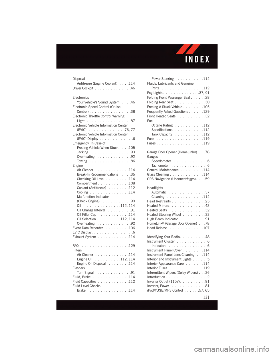
Disposal
Antifreeze (Engine Coolant)....114
Driver Cockpit..............46
Electronics
Yo u r Ve h i c l e ' s S o u n d S y s t e m....46
Electronic Speed Control (Cruise
Control) . . . . . . . . . . . . . . . .38
Electronic Throttle Control Warning
Light . . . . . . . . . . . . . . . . .87Electronic Vehicle Information Center(EVIC) . . . . . . . . . . . . . .76, 77Electronic Vehicle Information Center(EVIC) Display . . . . . . . . . . . . .6Emergency, In Case ofFreeing Vehicle When Stuck . . .105Jacking . . . . . . . . . . . . . . .93Overheating . . . . . . . . . . . . .92To w i n g . . . . . . . . . . . . . . . . 8 6EngineAir Cleaner.............114Break-In Recommendations....35Checking Oil Level.........114Compartment............108Coolant (Antifreeze)........112Cooling . . . . . . . . . . . . . . .114Malfunction Indicator(Check Engine)...........90Oil . . . . . . . . . . . . . .112, 114Oil Change Interval.........91Oil Filler Cap...........114Oil Selection . . . . . . . . .112, 114Overheating . . . . . . . . . . . . .92Event Data Recorder..........106EVIC Display . . . . . . . . . . . . . . . .6Exhaust System............114
FA Q . . . . . . . . . . . . . . . . . . . 1 2 9FiltersAir Cleaner.............114Engine Oil..........112, 114Engine Oil Disposal........114FlashersTu r n S i g n a l.............91Fluid, Brake . . . . . . . . . . . . . .114Fluid Capacities............112Fluid Level ChecksBrake . . . . . . . . . . . . . . .114
Power Steering..........114
Fluids, Lubricants and Genuine
Parts . . . . . . . . . . . . . . . . .112
Fog Lights . . . . . . . . . . . . . .37, 91
Folding Front Passenger Seat......28
Folding Rear Seat............30
Freeing A Stuck Vehicle . . . . . . . .105
Frequently Asked Questions......129
Front Heated Seats...........32
FuelOctane Rating . . . . . . . . . . .112Specifications...........112Ta n k C a p a c i t y...........112Fuse . . . . . . . . . . . . . . . . . .119Fuses . . . . . . . . . . . . . . . . . .119
Garage Door Opener (HomeLink®)...78GaugesSpeedometer.............6Ta c h o m e t e r..............6General Maintenance.........114Glass Cleaning.............114GPS Navigation (Uconnect®gps)....59
HeadlightsAutomatic . . . . . . . . . . . . . .37Cleaning..............114Head Restraints.............25Heated Mirrors..............43Heated Seats..............32Heated Steering Wheel.........33High Beam Indicator..........91HomeLink®(Garage Door Opener) . . .78Hood Release.............107
Identifying Your Radio..........48Instrument Cluster............6Indicators . . . . . . . . . . . . . . .6Instrument Panel Cover........114Instrument Panel Lens Cleaning . . .114Interior and Instrument Lights......5Interior Appearance Care.......114Interior Fuses..............119Intermittent Wipers (Delay Wipers) . . .36Introduction................2Inverter Outlet (115V)..........81Inverter, Power..............81iPod®/USB/MP3 Control......57,65
INDEX
131
Page 134 of 140
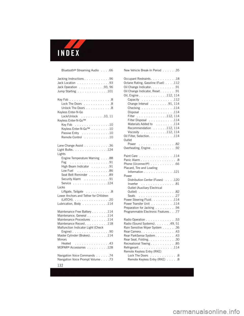
Bluetooth®Streaming Audio....66
Jacking Instructions . . . . . . . . . . .96
Jack Location . . . . . . . . . . . . . .93
Jack Operation . . . . . . . . . . .93, 96
Jump Starting.............101
Key Fob . . . . . . . . . . . . . . . . . .8
Lock The Doors............8
Unlock The Doors...........8
Keyless Enter-N-Go
Lock/Unlock . . . . . . . . . .10, 11
Keyless Enter-N-Go™
Key Fob . . . . . . . . . . . . . . .10
Keyless Enter-N-Go™ . . . . . . . .10
Passive Entry............10
Remote Control...........10
Lane Change Assist...........36
Light Bulbs . . . . . . . . . . . . . . .124
Lights
Engine Temperature Warning....88
Fog . . . . . . . . . . . . . . . . .91
High Beam Indicator . . . . . . . .91
Low Fuel . . . . . . . . . . . . . .86
Seat Belt Reminder.........89
Security Alarm...........91
Service...............124
Locks
Liftgate, Tailgate . . . . . . . . . . .8
Lower Anchors and Tether for CHildren(LATCH)................20Lubrication, Body...........114
Maintenance Free Battery . . . . . . .114Maintenance, General.........114Maintenance Procedures.......114Maintenance Record..........118Malfunction Indicator Light (CheckEngine)................90Master Cylinder (Brakes)........114MirrorsHeated...............43MOPAR®Accessories.........128
Navigation Voice Commands......74Navigation Voice Prompt Volume....73
New Vehicle Break-In Period . . . . . .35
Occupant Restraints...........18
Octane Rating, Gasoline (Fuel)....112
Oil Change Indicator...........91
Oil Change Indicator, Reset.......91
Oil, Engine............112, 114
Capacity..............112
Change Interval........91,114
Checking..............114
Disposal..............114Filter.............112, 114Filter Disposal...........114Materials Added to........114Recommendation......112, 114Viscosity...........112, 114Oil Filter, Selection...........114OutletPower................82Overheating, Engine...........92
Paint Care . . . . . . . . . . . . . . .114Panic Alarm................8Phone (Uconnect®)...........66Placard, Tire and LoadingInformation . . . . . . . . . . . . .121PowerDistribution Center (Fuses)....120Inverter . . . . . . . . . . . . . . .81Outlet (Auxiliary ElectricalOutlet) . . . . . . . . . . . . . . . .82Seats................27Power Steering Fluid..........114Power Transfer Unit..........114Preparation for Jacking.........94Programmable Electronic Features . . .77
Radio Operation.............53Radio (Sound Systems).......49,51Rain Sensitive Wiper System......36Rear Camera...............43Rear ParkSense System.........43Rear Seat, Folding............30Recreational Towing...........85Refrigerant . . . . . . . . . . . . . . .114Remote Keyless Entry (RKE)Lock The Doors............8Remote Keyless Entry (RKE).....8
INDEX
132