brake light DODGE JOURNEY 2017 1.G Owner's Manual
[x] Cancel search | Manufacturer: DODGE, Model Year: 2017, Model line: JOURNEY, Model: DODGE JOURNEY 2017 1.GPages: 510
Page 399 of 510
•Trailer brakes are recommended for trailers over
1,000 lbs (453 kg) and required for trailers in excess of
2,000 lbs (907 kg).
WARNING!
• Do not connect trailer brakes to your vehicle’s hy-
draulic brake lines. It can overload your brake sys-
tem and cause it to fail. You might not have brakes
when you need them and could have a collision.
• Towing any trailer will increase your stopping dis-
tance. When towing you should allow for additional
space between your vehicle and the vehicle in front
of you. Failure to do so could result in a collision.
CAUTION!
If the trailer weighs more than 1,000 lbs (453 kg)
loaded, it should have its own brakes and they should
be of adequate capacity. Failure to do this could lead to
accelerated brake lining wear, higher brake pedal
effort, and longer stopping distances.
Towing Requirements — Trailer Lights And Wiring
(If Equipped)
Whenever you pull a trailer, regardless of the trailer size,
stoplights and turn signals on the trailer are required for
motoring safety.
The Trailer Tow Package may include a four- and seven-pin
wiring harness. Use a factory approved trailer harness and
connector.
NOTE: Do not cut or splice wiring into the vehicles wiring
harness.
The electrical connections are all complete to the vehicle
but you must mate the harness to a trailer connector. Refer
to the following illustrations.
5
STARTING AND OPERATING 397
Page 417 of 510
WARNING!
To avoid the risk of forcing the vehicle off the jack, do
not tighten the lug nuts fully until the vehicle has been
lowered. Failure to follow this warning may result in
serious injury.
8. Lower the vehicle by turning the jack screw counter- clockwise with the jack handle.
9. Finish tightening the lug nuts. Push down on the wrench while at the end of the handle for increased
leverage. Tighten the lug nuts in a star pattern until each
nut has been tightened twice. For the correct lug nut
torque refer to Torque Specifications in this section. If in
doubt about the correct tightness, have them checked
with a torque wrench by your authorized dealer or
service station.
10. Lower the jack to its fully closed position.
11. Place the deflated (flat) tire in the cargo area. Do not
stow the deflated tire in the spare tire stowage
location. Have the deflated (flat) tire repaired or re-
placed as soon as possible. 12. To stow the winch cable and retainer, fit the assembled
jack-handle over the winch drive nut. Rotate the jack-
handle assembly clockwise until you hear the winch
mechanism click three times. It cannot be over tight-
ened.
13. Stow the jack-handle and jack. Remove the wheel blocks from the vehicle and release the park brake.
14. Check the tire pressure as soon as possible. Adjust the tire pressure as required.
Road Tire Installation
Vehicles Equipped With Wheel Covers
1. Mount the road tire on the axle.
2. To ease the installation process for steel wheels withwheel covers, install two lug nuts on the mounting
studs which are on each side of the valve stem. Install
the lug nuts with the cone shaped end of the nut toward
the wheel. Lightly tighten the lug nuts.
6
WHAT TO DO IN EMERGENCIES 415
Page 420 of 510
NOTE:When using a portable battery booster pack follow
the manufacturer’s operating instructions and precautions.
Preparations For Jump-Start
The battery in your vehicle is located between the left front
headlight assembly and the left front wheel splash shield.
To allow jump-starting, there are remote battery posts
located on the left side of the engine compartment.
WARNING!
• Take care to avoid the radiator cooling fan whenever
the hood is raised. It can start anytime the ignition
switch is ON. You can be injured by moving fan
blades.
• Remove any metal jewelry such as rings, watch
bands and bracelets that could make an inadvertent
electrical contact. You could be seriously injured.
• Batteries contain sulfuric acid that can burn your
skin or eyes and generate hydrogen gas which is
flammable and explosive. Keep open flames or
sparks away from the battery.
1. Set the parking brake, shift the automatic transmission into PARK and turn the ignition to LOCK.
2. Turn off the heater, radio, and all unnecessary electrical accessories.
3. Remove the protective cover over the remote positive (+) battery post. To remove the cover, push the locking
tab and pull upward on the cover.
Remote Battery Posts
1 — Remote Positive (+) Post (Covered With Protective Cap)
2 — Remote Negative (-) Post 418 WHAT TO DO IN EMERGENCIES
Page 432 of 510
ENGINE COMPARTMENT — 3.6L
ONBOARD DIAGNOSTIC SYSTEM — OBD II
Your vehicle is equipped with a sophisticated onboard
diagnostic system called OBD II. This system monitors the
performance of the emissions, engine, and automatic trans-
mission control systems. When these systems are operatingproperly, your vehicle will provide excellent performance
and fuel economy, as well as engine emissions well within
current government regulations.
If any of these systems require service, the OBD II system
will turn on the “Malfunction Indicator Light” (MIL). It
1 — Engine Coolant Reservoir
5 — Air Cleaner Filter
2 — Power Steering Fluid Reservoir 6 — Washer Fluid Reservoir
3 — Brake Fluid Reservoir 7 — Engine Oil Dipstick
4 — Power Distribution Center (Fuses) 8 — Engine Oil Fill
430 MAINTAINING YOUR VEHICLE
Page 452 of 510
WARNING!
Riding the brakes can lead to brake failure and possi-
bly a collision. Driving with your foot resting or riding
on the brake pedal can result in abnormally high brake
temperatures, excessive lining wear, and possible
brake damage. You would not have your full braking
capacity in an emergency.
Master Cylinder — Brake Fluid Level Check
Check the fluid level in the master cylinder immediately if
the “Brake Warning Light” indicates system failure.
Check the fluid level in the master cylinder when perform-
ing underhood services.
Clean the top of the master cylinder area before removing
the cap. If necessary, add fluid to bring the fluid level up to
the requirements described on the brake fluid reservoir.
Overfilling of fluid is not recommended because it may
cause leaking in the system.
Fluid level can be expected to fall as the brake pads wear.
Brake fluid level should be checked when pads are re-
placed. However, low fluid level may be caused by a leak
and a checkup may be needed.Use only manufacturer’s recommended brake fluid. Refer
to “Fluids, Lubricants, And Genuine Parts” in “Maintain-
ing Your Vehicle” for further information.
WARNING!
•
Use only manufacturer’s recommended brake fluid.
Refer to “Fluids, Lubricants, And Genuine Parts” in
“Maintaining Your Vehicle” for further information.
Using the wrong type of brake fluid can severely
damage your brake system and/or impair its perfor-
mance. The proper type of brake fluid for your
vehicle is also identified on the original factory
installed hydraulic master cylinder reservoir.
• To avoid contamination from foreign matter or mois-
ture, use only new brake fluid or fluid that has been
in a tightly closed container. Keep the master cylin-
der reservoir cap secured at all times. Brake fluid in
a open container absorbs moisture from the air
resulting in a lower boiling point. This may cause it
to boil unexpectedly during hard or prolonged brak-
ing, resulting in sudden brake failure. This could
result in a collision.
(Continued)
450 MAINTAINING YOUR VEHICLE
Page 465 of 510
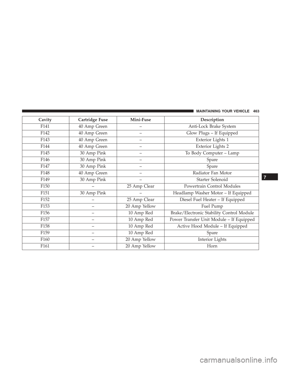
CavityCartridge Fuse Mini-Fuse Description
F141 40 Amp Green –Anti-Lock Brake System
F142 40 Amp Green –Glow Plugs – If Equipped
F143 40 Amp Green –Exterior Lights 1
F144 40 Amp Green –Exterior Lights 2
F145 30 Amp Pink –To Body Computer – Lamp
F146 30 Amp Pink – Spare
F147 30 Amp Pink – Spare
F148 40 Amp Green –Radiator Fan Motor
F149 30 Amp Pink –Starter Solenoid
F150 –25 Amp Clear Powertrain Control Modules
F151 30 Amp Pink –Headlamp Washer Motor – If Equipped
F152 –25 Amp Clear Diesel Fuel Heater – If Equipped
F153 –20 Amp Yellow Fuel Pump
F156 –10 Amp Red Brake/Electronic Stability Control Module
F157 –10 Amp Red Power Transfer Unit Module – If Equipped
F158 –10 Amp Red Active Hood Module – If Equipped
F159 –10 Amp Red Spare
F160 –20 Amp Yellow Interior Lights
F161 –20 Amp Yellow Horn
7
MAINTAINING YOUR VEHICLE 463
Page 480 of 510
MAINTENANCE SCHEDULE
Your vehicle is equipped with an automatic oil change
indicator system. The oil change indicator system will
remind you that it is time to take your vehicle in for
scheduled maintenance.
Based on engine operation conditions, the oil change
indicator message will illuminate. This means that service
is required for your vehicle. Operating conditions such as
frequent short-trips, trailer tow, extremely hot or cold
ambient temperatures, and E-85 fuel usage will influence
when the “Change Oil” or “Oil Change Required” message
is displayed. Severe Operating Conditions can cause the
change oil message to illuminate as early as 3,500 miles
(5,600 km) since last reset. Have your vehicle serviced as
soon as possible, within the next 500 miles (805 km).
Your authorized dealer will reset the oil change indicator
message after completing the scheduled oil change. If a
scheduled oil change is performed by someone other than
your authorized dealer, the message can be reset by
referring to the steps described under “Instrument Cluster
Display” in “Understanding Your Instrument Panel” for
further information.NOTE:
Under no circumstances should oil change inter-
vals exceed 10,000 miles (16,000 km), twelve months or 350
hours of engine run time, whichever comes first. The 350
hours of engine run or idle time is generally only a concern
for fleet customers.
Severe Duty All Models
Change Engine Oil at 4,000 miles (6,500 km) if the vehicle
is operated in a dusty and off road environment or is
operated predominately at idle or only very low engine
RPM’s. This type of vehicle use is considered Severe Duty.
Once A Month Or Before A Long Trip:
• Check engine oil level.
• Check windshield washer fluid level.
• Check tire pressure and look for unusual wear or
damage. Rotate tires at the first sign of irregular wear,
even if it occurs before the oil indicator system turns on.
• Check the fluid levels of the coolant reservoir, brake
master cylinder, power steering, and transmission (4-
speed only) and fill as needed.
• Check function of all interior and exterior lights.
478 MAINTENANCE SCHEDULES
Page 492 of 510
About Your Brakes..................... .341, 343
Adding Engine Coolant (Antifreeze) .............446
Adding Fuel ............................. .386
Adding Washer Fluid ....................... .443
Additives, Fuel ........................... .382
Adjust Down ................................ .149
Forward .............................. .149
Rearward ............................. .149
Up.................................. .149
AirBag ..................................48 Air Bag Operation .........................50
Air Bag Warning Light .....................57
Driver Knee Air Bag .......................51
Enhanced Accident Response ..............56, 425
Event Data Recorder (EDR) .................425
If A Deployment Occurs ....................55
Knee Impact Bolsters .......................50
Maintaining Your Air Bag System ..............58
Side Air Bags ............................51
Air Bag Light ....................... .57, 82, 226
Air Bag Maintenance .........................58
Air Cleaner, Engine (Engine Air Cleaner Filter) ......437
Air Conditioner Maintenance ..................438
Air Conditioning Filter ...................319, 439 Air Conditioning, Operating Tips
............318, 320
Air Conditioning, Rear Zone ...............304, 314
Air Conditioning Refrigerant ...............438, 439
Air Conditioning System .....................438
Air Pressure, Tires ......................... .363
Alarm, Panic ...............................17
Alarm (Security Alarm) ....................13, 228
Alarm System (Security Alarm) .................13
All Wheel Drive (AWD) ..................... .337
Alterations/Modifications, Vehicle ................6
Antifreeze (Engine Coolant) ................446, 472
Disposal .............................. .448
Anti-Lock Brake System (ABS) .................344
Anti-Lock Warning Light .....................238
Appearance Care .......................... .454
Arming
System (Security Alarm) ................13
Assist, Hill Start .......................... .346
Auto Down Power Windows ...................31
Automatic Dimming Mirror ....................89
Automatic Door Locks ........................24
Automatic Headlights ...................... .168
Automatic Oil Change Indicator ................244
Automatic Transmission ..................329, 451
Adding Fluid .....................452, 453, 475
Fluid And Filter Changes ...................453
490 INDEX
Page 493 of 510
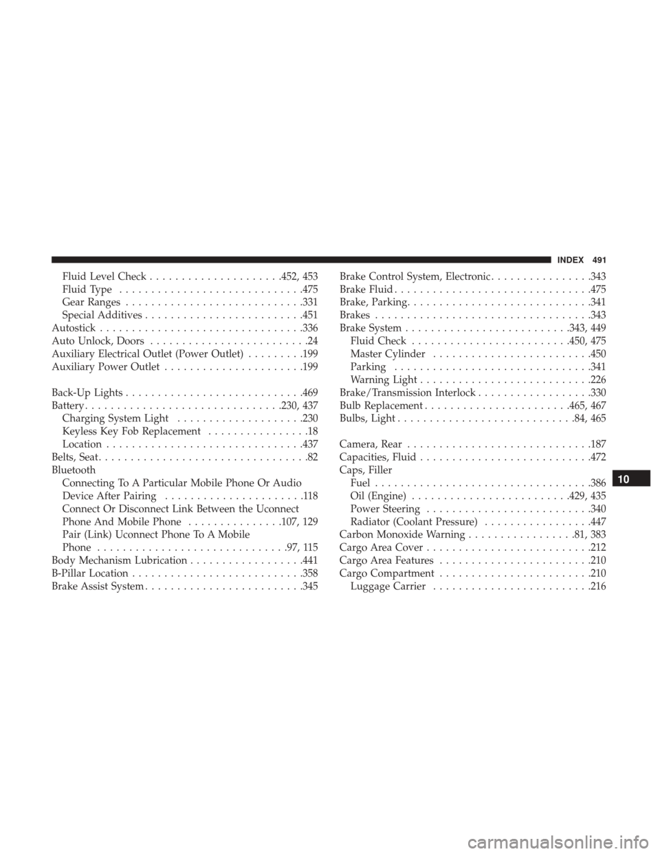
Fluid Level Check.....................452, 453
Fluid Type ............................ .475
Gear Ranges ........................... .331
Special Additives ........................ .451
Autostick ............................... .336
Auto Unlock, Doors .........................24
Auxiliary Electrical Outlet (Power Outlet) .........199
Auxiliary Power Outlet ..................... .199
Back-Up Lights ........................... .469
Battery .............................. .230, 437
Charging System Light ....................230
Keyless Key Fob Replacement ................18
Location .............................. .437
Belts, Seat .................................82
Bluetooth Connecting To A Particular Mobile Phone Or Audio
Device After Pairing ......................118
Connect Or Disconnect Link Between the Uconnect
Phone And Mobile Phone ...............107, 129
Pair (Link) Uconnect Phone To A Mobile
Phone ............................. .97, 115
Body Mechanism Lubrication ..................441
B-Pillar Location .......................... .358
Brake Assist System ........................ .345Brake Control System, Electronic
................343
Brake Fluid .............................. .475
Brake, Parking ............................ .341
Brakes ................................. .343
Brake System ......................... .343, 449
Fluid Check ........................ .450, 475
Master Cylinder ........................ .450
Parking .............................. .341
Warning Light .......................... .226
Brake/Transmission Interlock ..................330
Bulb Replacement ...................... .465, 467
Bulbs, Light ........................... .84, 465
Camera, Rear ............................ .187
Capacities, Fluid .......................... .472
Caps, Filler Fuel ................................. .386
Oil
(Engine) ........................ .429, 435
Power Steering ......................... .340
Radiator (Coolant Pressure) .................447
Carbon Monoxide Warning .................81, 383
Cargo Area Cover ......................... .212
Cargo Area Features ....................... .210
Cargo Compartment ....................... .210
Luggage Carrier ........................ .21610
INDEX 491
Page 495 of 510
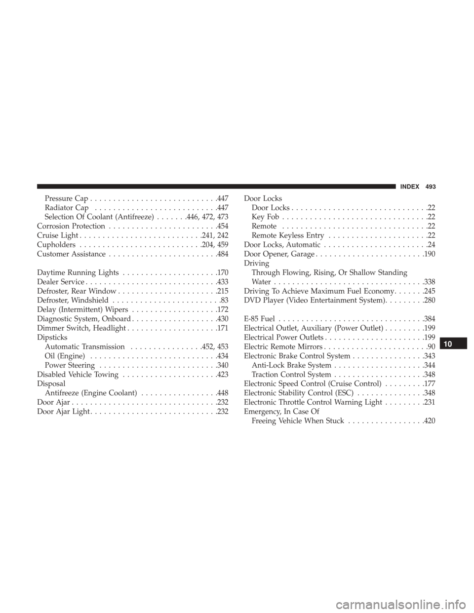
Pressure Cap........................... .447
Radiator Cap .......................... .447
Selection Of Coolant (Antifreeze) .......446, 472, 473
Corrosion Protection ....................... .454
Cruise Light .......................... .241, 242
Cupholders .......................... .204, 459
Customer Assistance ....................... .484
Daytime Running Lights .....................170
Dealer Service ............................ .433
Defroster, Rear Window ..................... .215
Defroster, Windshield ........................83
Delay (Intermittent) Wipers ...................172
Diagnostic System, Onboard ...................430
Dimmer Switch, Headlight ....................171
Dipsticks Automatic Transmission ................452, 453
Oil (Engine) ........................... .434
Power Steering ......................... .340
Disabled Vehicle Towing .....................423
Disposal Antifreeze (Engine Coolant) .................448
Door Ajar ............................... .232
Door Ajar Light ........................... .232Door Locks
Door Locks ..............................22
KeyFob................................22
Remote ................................22
Remote Keyless Entry ......................22
Door Locks, Automatic .......................24
Door Opener, Garage ....................... .190
Driving Through Flowing, Rising, Or Shallow Standing
Water ................................ .338
Driving To Achieve Maximum Fuel Economy .......245
DVD Player (Video Entertainment System) .........280
E-85 Fuel ............................... .384
Electrical Outlet, Auxiliary (Power Outlet) .........199
Electrical Power Outlets ..................... .199
Electric Remote Mirrors .......................90
Electronic Brake Control System ................343
Anti-Lock Brake System ....................344
T
raction Control System ....................348
Electronic Speed Control (Cruise Control) .........177
Electronic Stability Control (ESC) ...............348
Electronic Throttle Control Warning Light .........231
Emergency, In Case Of Freeing Vehicle When Stuck .................420
10
INDEX 493