service DODGE JOURNEY 2019 Owners Manual
[x] Cancel search | Manufacturer: DODGE, Model Year: 2019, Model line: JOURNEY, Model: DODGE JOURNEY 2019Pages: 524, PDF Size: 5.29 MB
Page 6 of 524
INTRODUCTION
Dear Customer,
Congratulations on selecting your new vehicle. Be assured
that it represents precision workmanship, distinctive styl-
ing, and high quality. This Owner ’s Manual has been
prepared with the assistance of service and engineering
specialists to acquaint you with the operation and mainte-
nance of your vehicle. It is supplemented by Warranty
Information, and customer oriented documents. In the
attached Warranty Booklet, you will find a description of
the services that FCA offers to its customers, the Warranty
Certificate and the details of the terms and conditions for
maintaining its validity. Please take the time to read all of
these publications carefully before driving your vehicle for
the first time. Following the instructions, recommenda-
tions, tips, and important warnings in this manual will
help assure safe and enjoyable operation of your vehicle.
Be sure you are familiar with all vehicle controls, particu-
larly those used for braking, steering, transmission, and
transfer case shifting (if equipped). Learn how your vehicle
handles on different road surfaces. Your driving skills will
improve with experience.This Owner ’s Manual describes all versions of this vehicle.
Options and equipment dedicated to specific markets or
versions are not expressly indicated in the text. Therefore,
you should only consider the information which is related
to the trim level, engine, and version that you have
purchased. Any content introduced throughout the Own-
er ’s Information, that may or may not be applicable to your
vehicle, will be identified with the wording “If Equipped”.
All data contained in this publication are intended to help
you use your vehicle in the best possible way. FCA aims at
a constant improvement of the vehicles produced. For this
reason, it reserves the right to make changes to the model
described for technical and/or commercial reasons. For
further information, contact an authorized dealer.
NOTE:
After reviewing the Owner ’s Information, it should
be stored in the vehicle for convenient referencing, and
remain with the vehicle when sold.
When it comes to service, remember that an authorized
dealer knows your vehicle best, has factory-trained techni-
cians and genuine MOPAR® parts, and cares about your
satisfaction.
4 INTRODUCTION
Page 29 of 524
General Information
The following regulatory statement applies to all radio
frequency (RF) devices equipped in this vehicle:
This device complies with Part 15 of the FCC Rules and
with Industry Canada license-exempt RSS standard(s).
Operation is subject to the following two conditions:
1. This device may not cause harmful interference, and
2. This device must accept any interference received, in-cluding interference that may cause undesired opera-
tion.
NOTE: Changes or modifications not expressly approved
by the party responsible for compliance could void the
user ’s authority to operate the equipment.
SENTRY KEY
The Sentry Key Immobilizer system prevents unauthorized
vehicle operation by disabling the engine. The system does
not need to be armed or activated. Operation is automatic,
regardless of whether the vehicle is locked or unlocked.
The system uses a key fob and a Keyless Push Button
Ignition, and a RF receiver to prevent unauthorized vehicle
operation. Therefore, only key fobs that are programmed to
the vehicle can be used to start and operate the vehicle. If an invalid key fob is used to attempt to start and operate
the vehicle, the system will not allow the engine to crank.
If an invalid key fob is used to start the engine, the system
will shut the engine off in two seconds.
After placing the ignition to the ON/RUN mode, the
vehicle security light will turn on for three seconds for a
bulb check. If the light remains on after the bulb check, it
indicates that there is a problem with the electronics. In
addition, if the light begins to flash after the bulb check, it
indicates that someone used an invalid key fob to start the
engine. Either of these conditions will result in the engine
being shut off after two seconds.
If the vehicle security light turns on during normal vehicle
operation (vehicle running for longer than 10 seconds), it
indicates that there is a fault in the electronics. Should this
occur, have the vehicle serviced as soon as possible by an
authorized dealer.
CAUTION!
The Sentry Key Immobilizer system is not compatible
with some aftermarket remote starting systems. Use of
these systems may result in vehicle starting problems
and loss of security protection.
3
GETTING TO KNOW YOUR VEHICLE 27
Page 30 of 524
All of the key fobs provided with your new vehicle have
been programmed to the vehicle electronics.
Key Programming
Programming key fobs may be performed at an authorized
dealer.
Replacement Keys
NOTE:Only key fobs that are programmed to the vehicle
electronics can be used to start and operate the vehicle.
Once a key fob is programmed to a vehicle, it cannot be
programmed to any other vehicle.
CAUTION!
• Always remove the key fobs from the vehicle and
lock all doors when leaving the vehicle unattended.
• For vehicles equipped with Keyless Enter-N-Go —
Ignition, always remember to place the ignition in
the OFF position.
NOTE: Duplication of key fobs may be performed at an
authorized dealer. This procedure consists of programming
a blank key fob to the vehicle electronics. A blank key fob
is one that has never been programmed. When having the Sentry Key Immobilizer System serviced,
bring all vehicle keys with you to an authorized dealer.
General Information
The following regulatory statement applies to all radio
frequency (RF) devices equipped in this vehicle:
This device complies with Part 15 of the FCC Rules and
with Industry Canada license-exempt RSS standard(s).
Operation is subject to the following two conditions:
1. This device may not cause harmful interference, and
2. This device must accept any interference received, in-
cluding interference that may cause undesired opera-
tion.
NOTE: Changes or modifications not expressly approved
by the party responsible for compliance could void the
user ’s authority to operate the equipment.
28 GETTING TO KNOW YOUR VEHICLE
Page 34 of 524
Power Door Locks
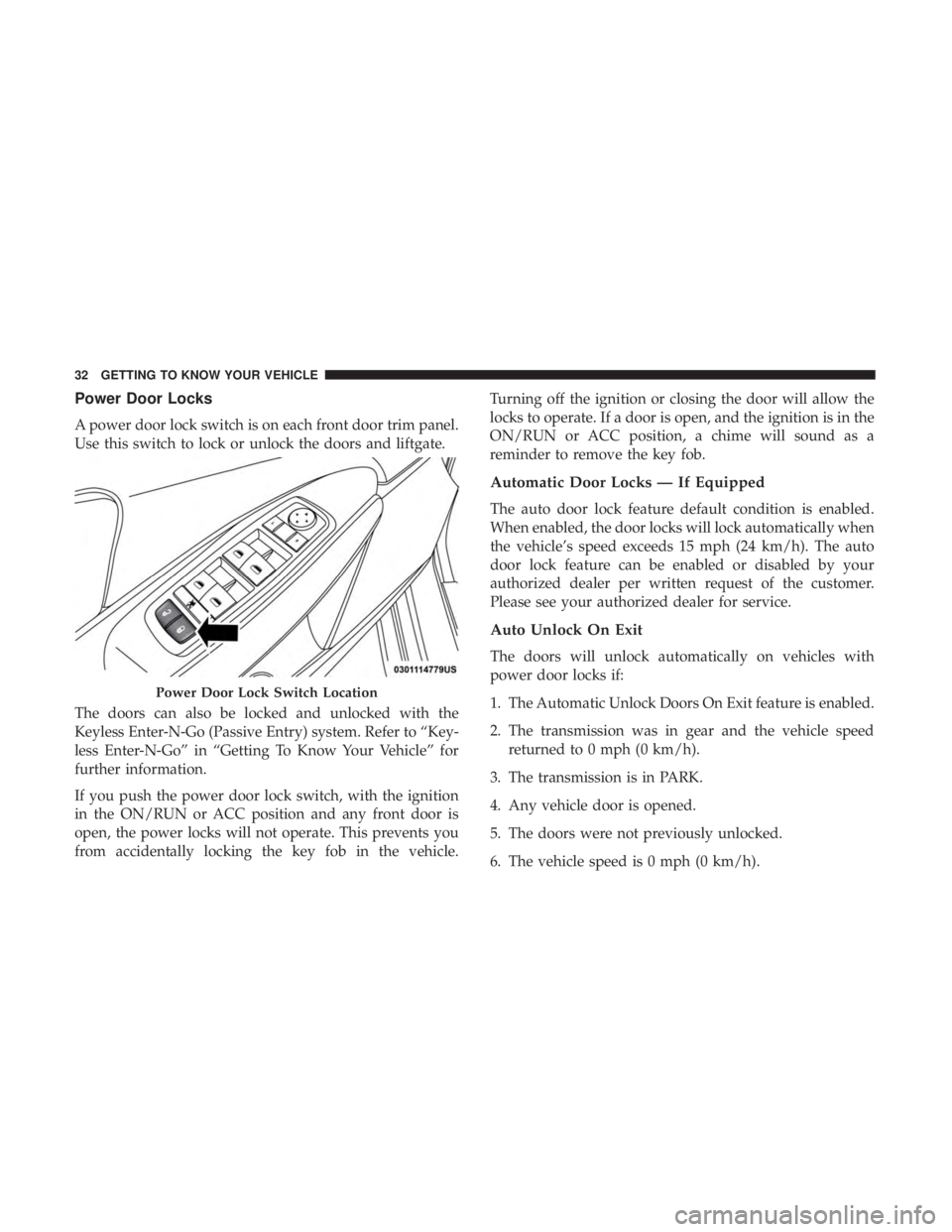
A power door lock switch is on each front door trim panel.
Use this switch to lock or unlock the doors and liftgate.
The doors can also be locked and unlocked with the
Keyless Enter-N-Go (Passive Entry) system. Refer to “Key-
less Enter-N-Go” in “Getting To Know Your Vehicle” for
further information.
If you push the power door lock switch, with the ignition
in the ON/RUN or ACC position and any front door is
open, the power locks will not operate. This prevents you
from accidentally locking the key fob in the vehicle.Turning off the ignition or closing the door will allow the
locks to operate. If a door is open, and the ignition is in the
ON/RUN or ACC position, a chime will sound as a
reminder to remove the key fob.
Automatic Door Locks — If Equipped
The auto door lock feature default condition is enabled.
When enabled, the door locks will lock automatically when
the vehicle’s speed exceeds 15 mph (24 km/h). The auto
door lock feature can be enabled or disabled by your
authorized dealer per written request of the customer.
Please see your authorized dealer for service.
Auto Unlock On Exit
The doors will unlock automatically on vehicles with
power door locks if:
1. The Automatic Unlock Doors On Exit feature is enabled.
2. The transmission was in gear and the vehicle speed
returned to 0 mph (0 km/h).
3. The transmission is in PARK.
4. Any vehicle door is opened.
5. The doors were not previously unlocked.
6. The vehicle speed is 0 mph (0 km/h).
Power Door Lock Switch Location
32 GETTING TO KNOW YOUR VEHICLE
Page 56 of 524

NOTE:
•The head restraints should only be removed by qualified
technicians, for service purposes only. If either of the
head restraints require removal, see your authorized
dealer.
• In the event of deployment of an Active Head Restraint,
refer to “Occupant Restraints/Supplemental Active
Head Restraints (AHR)/Resetting Active Head Re-
straints (AHR)” in “Safety” for further information.
WARNING!
• All occupants, including the driver, should not oper-
ate a vehicle or sit in a vehicle’s seat until the head
restraints are placed in their proper positions in
order to minimize the risk of neck injury in the event
of a collision.
• Do not place items over the top of the Active Head
Restraint, such as coats, seat covers or portable DVD
players. These items may interfere with the opera-
tion of the Active Head Restraint in the event of a
collision and could result in serious injury or death.
• Active Head Restraints may be deployed if they are
struck by an object such as a hand, foot or loose
cargo. To avoid accidental deployment of the Active
Head Restraint ensure that all cargo is secured, as
loose cargo could contact the Active Head Restraint
during sudden stops. Failure to follow this warning
could cause personal injury if the Active Head Re-
straint is deployed.
Active Head Restraint (Tilted)
54 GETTING TO KNOW YOUR VEHICLE
Page 102 of 524
Summer Operation
The engine cooling system must be protected with a
high-quality antifreeze coolant to provide proper corrosion
protection and to protect against engine overheating. OAT
coolant (conforming to MS.90032) is recommended. Refer
to “Fluids And Lubricants” in “Technical Specifications”
for proper coolant selection.
Winter Operation
To ensure the best possible heater and defroster perfor-
mance, make sure the engine cooling system is functioning
properly and the proper amount, type, and concentration
of coolant is used. Refer to “Fluids And Lubricants” in
“Technical Specifications” for proper coolant selection. Use
of the air Recirculation mode during Winter months is not
recommended, because it may cause window fogging.
Vacation/Storage
Before you store your vehicle, or keep it out of service (i.e.,
vacation) for two weeks or more, run the air conditioning
system at idle for about five minutes, in fresh air with the
blower setting on high. This will ensure adequate system
lubrication to minimize the possibility of compressor dam-
age when the system is started again.
Window Fogging
Vehicle windows tend to fog on the inside in mild, rainy,
and/or humid weather. To clear the windows, select De-
frost or Mix mode and increase the front blower speed. Do
not use the Recirculation mode without A/C for long
periods, as fogging may occur.
CAUTION!
Failure to follow these cautions can cause damage to
the heating elements:
•Use care when washing the inside of the rear win-
dow. Do not use abrasive window cleaners on the
interior surface of the window. Use a soft cloth and a
mild washing solution, wiping parallel to the heat-
ing elements. Labels can be peeled off after soaking
with warm water.
• Do not use scrapers, sharp instruments, or abrasive
window cleaners on the interior surface of the win-
dow.
• Keep all objects a safe distance from the window.
100 GETTING TO KNOW YOUR VEHICLE
Page 139 of 524
Instrument Cluster Descriptions
1. Tachometer•Indicates the engine speed in revolutions per minute
(RPM x 1000).
2. Instrument Cluster Display •When the appropriate conditions exist, this display
shows the instrument cluster display messages. Refer
to “Instrument Cluster Display” in “Getting To Know
Your Instrument Panel” for further information.
3. Speedometer •Indicates vehicle speed.
4. Fuel Gauge •The pointer shows the level of fuel in the fuel tank
when the Keyless Push Button Ignition is in the
ON/RUN position.
•
The fuel pump symbol points to the side of the
vehicle where the fuel door is located.
5. Temperature Gauge
•The temperature gauge shows engine coolant tem-
perature. Any reading within the normal range indi-
cates that the engine cooling system is operating
satisfactorily. •
The gauge pointer will likely indicate a higher tem-
perature when driving in hot weather, up mountain
grades, or when towing a trailer. It should not be
allowed to exceed the upper limits of the normal
operating range.
WARNING!
A hot engine cooling system is dangerous. You or
others could be badly burned by steam or boiling
coolant. You may want to call an authorized dealer for
service if your vehicle overheats. If you decide to look
under the hood yourself, see “Servicing And Mainte-
nance.” Follow the warnings under the Cooling System
Pressure Cap paragraph.
CAUTION!
Driving with a hot engine cooling system could dam-
age your vehicle. If the temperature gauge reads “H,”
pull over and stop the vehicle. Idle the vehicle with the
air conditioner turned off until the pointer drops back
into the normal range. If the pointer remains on the
“H,” turn the engine off immediately and call an
authorized dealer for service.
4
GETTING TO KNOW YOUR INSTRUMENT PANEL 137
Page 147 of 524

•Turning on all possible vehicle electrical loads (e.g.
HVAC to max settings, exterior and interior lights,
overloaded power outlets +12V, 115V AC, USB ports)
during certain driving conditions (city driving, towing,
frequent stopping, etc.).
• Installing options like additional lights, upfitter electri-
cal accessories, audio systems, alarms and similar de-
vices.
• Unusual driving cycles (short trips separated by long
parking periods).
• The vehicle was parked for an extended period of time
(weeks, months).
• The battery was recently replaced and was not charged
completely.
• The battery was discharged by an electrical load left on
when the vehicle was parked.
• The battery was used for an extended period with the
engine not running to supply radio, lights, chargers,
+12V portable appliances like vacuum cleaners, game
consoles and similar devices. What to do when an electrical load reduction action
message is present (“Battery Saver On” or “Battery Saver
Mode”)
During a trip:
•
Reduce power to unnecessary loads if possible:
– Turn off redundant lights (interior or exterior)
– Check what may be plugged in to power outlets +12V, 115V AC, USB ports
– Check HVAC settings (blower, temperature)
– Check the audio settings (volume)
After a trip:
• Check if any aftermarket equipment was installed (ad-
ditional lights, upfitter electrical accessories, audio sys-
tems, alarms) and review specifications if any (load and
Ignition Off Draw currents).
• Evaluate the latest driving cycles (distance, driving time
and parking time).
• The vehicle should have service performed if the mes-
sage is still present during consecutive trips, and if the
evaluation and driving pattern of the vehicle did not
help to identify the cause.
4
GETTING TO KNOW YOUR INSTRUMENT PANEL 145
Page 149 of 524
been corrected. If the problem is related to the brake
booster, the ABS pump will run when applying the brake,
and a brake pedal pulsation may be felt during each stop.
The dual brake system provides a reserve braking capacity
in the event of a failure to a portion of the hydraulic
system. A leak in either half of the dual brake system is
indicated by the Brake Warning Light, which will turn on
when the brake fluid level in the master cylinder has
dropped below a specified level.
The light will remain on until the cause is corrected.
NOTE:The light may flash momentarily during sharp
cornering maneuvers, which change fluid level conditions.
The vehicle should have service performed, and the brake
fluid level checked.
If brake failure is indicated, immediate repair is necessary.
WARNING!
Driving a vehicle with the red brake light on is
dangerous. Part of the brake system may have failed. It
will take longer to stop the vehicle. You could have a
collision. Have the vehicle checked immediately. Vehicles equipped with the Anti-Lock Brake System (ABS)
are also equipped with Electronic Brake Force Distribution
(EBD). In the event of an EBD failure, the Brake Warning
Light will turn on along with the ABS Light. Immediate
repair to the ABS system is required.
Operation of the Brake Warning Light can be checked by
turning the ignition switch from the OFF position to the
ON/RUN position. The light should illuminate for ap-
proximately two seconds. The light should then turn off
unless the parking brake is applied or a brake fault is
detected. If the light does not illuminate, have the light
inspected by an authorized dealer.
The light also will turn on when the parking brake is
applied with the ignition switch in the ON/RUN position.
NOTE:
This light shows only that the parking brake is
applied. It does not show the degree of brake application.
— Vehicle Security Warning Light — If Equipped
This light will flash at a fast rate for approximately 15
seconds when the vehicle security alarm is arming, and
then will flash slowly until the vehicle is disarmed.
4
GETTING TO KNOW YOUR INSTRUMENT PANEL 147
Page 150 of 524
— Engine Coolant Temperature Warning Light
This warning light warns of an overheated engine condi-
tion. If the engine coolant temperature is too high, this
indicator will illuminate and a single chime will sound. If
the temperature reaches the upper limit, a continuous
chime will sound for four minutes or until the engine is
able to cool: whichever comes first.
If the light turns on while driving, safely pull over and stop
the vehicle. If the A/C system is on, turn it off. Also, shift
the transmission into NEUTRAL and idle the vehicle. If the
temperature reading does not return to normal, turn the
engine off immediately and call for service.
Refer to “If Your Engine Overheats” in “In Case Of
Emergency” for further information.
— Transmission Temperature Warning Light — If
Equipped
This warning light will illuminate to warn of a high
transmission fluid temperature. This may occur with
strenuous usage such as trailer towing. If this light turns
on, stop the vehicle and run the engine at idle or slightly
faster, with the transmission in PARK or NEUTRAL, until the light turns off. Once the light turns off, you may
continue to drive normally.
WARNING!
If you continue operating the vehicle when the Trans-
mission Temperature Warning Light is illuminated you
could cause the fluid to boil over, come in contact with
hot engine or exhaust components and cause a fire.
CAUTION!
Continuous driving with the Transmission Tempera-
ture Warning Light illuminated will eventually cause
severe transmission damage or transmission failure.
— Battery Charge Warning Light
This warning light will illuminate when the battery is not
charging properly. If it stays on while the engine is run-
ning, there may be a malfunction with the charging system.
Contact an authorized dealer as soon as possible.
This indicates a possible problem with the electrical system
or a related component.
148 GETTING TO KNOW YOUR INSTRUMENT PANEL