engine DODGE JOURNEY 2020 User Guide
[x] Cancel search | Manufacturer: DODGE, Model Year: 2020, Model line: JOURNEY, Model: DODGE JOURNEY 2020Pages: 396, PDF Size: 25.53 MB
Page 33 of 396
GETTING TO KNOW YOUR VEHICLE 31
direction of the switch. Release the switch when
the desired position has been reached.
Tilting The Seat Up Or Down
The angle of the seat cushion can be adjusted
in four directions. Pull upward or push
downward on the front or rear of the seat
switch; the front or rear of the seat cushion will
move in the direction of the switch. Release the
switch when the desired position is reached.
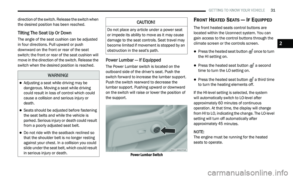
Power Lumbar — If Equipped
The Power Lumbar switch is located on the
outboard side of the driver's seat. Push the
switch forward to increase the lumbar support.
Push the switch rearward to decrease the
lumbar support. Pushing upward or downward
on the switch will raise or lower the position of
the support.
Power Lumbar Switch
FRONT HEATED SEATS — IF EQUIPPED
The front heated seats control buttons are
located within the Uconnect system. You can
gain access to the control buttons through the
climate screen or the controls screen.
Press the heated seat button once to turn
the HI setting on.
Press the heated seat button a second
time to turn the LO setting on.
Press the heated seat button a third time
to turn the heating elements off.
If the HI-level setting is selected, the system
will automatically switch to LO-level after
a p
proximately 60 minutes of continuous
o p
eration. At that time, the display will change
from HI to LO, indicating the change. The LO-level
setting will turn off automatically after
approximately 45 minutes.
NOTE:
The engine must be running for the heated
s e
ats to operate.
WARNING!
Adjusting a seat while driving may be
dangerous. Moving a seat while driving
could result in loss of control which could
cause a collision and serious injury or
death.
Seats should be adjusted before fastening
the seat belts and while the vehicle is
parked. Serious injury or death could result
from a poorly adjusted seat belt.
Do not ride with the seatback reclined so
that the shoulder belt is no longer resting
against your chest. In a collision you could
slide under the seat belt, which could result
in serious injury or death.
CAUTION!
Do not place any article under a power seat
or impede its ability to move as it may cause
damage to the seat controls. Seat travel may
become limited if movement is stopped by an
obstruction in the seat's path.
2
Page 38 of 396
36 GETTING TO KNOW YOUR VEHICLE
The heated steering wheel control button is
located within the Uconnect system. You can
gain access to the control button through the
climate screen or the controls screen.
Press the heated steering wheel button
once to turn the heating element on.
Press the heated steering wheel button a
second time to turn the heating element off.
NOTE:
The engine must be running for the heated
s t
eering wheel to operate.
Vehicles Equipped With Remote Start
On models that are equipped with remote start,
t h
e heated steering wheel can be programmed
to come on during a remote start through the
Uconnect system. Refer to “Uconnect Settings”
in “Multimedia” for further information.
MIRRORS
INSIDE DAY/NIGHT MIRROR — IF
E
QUIPPED
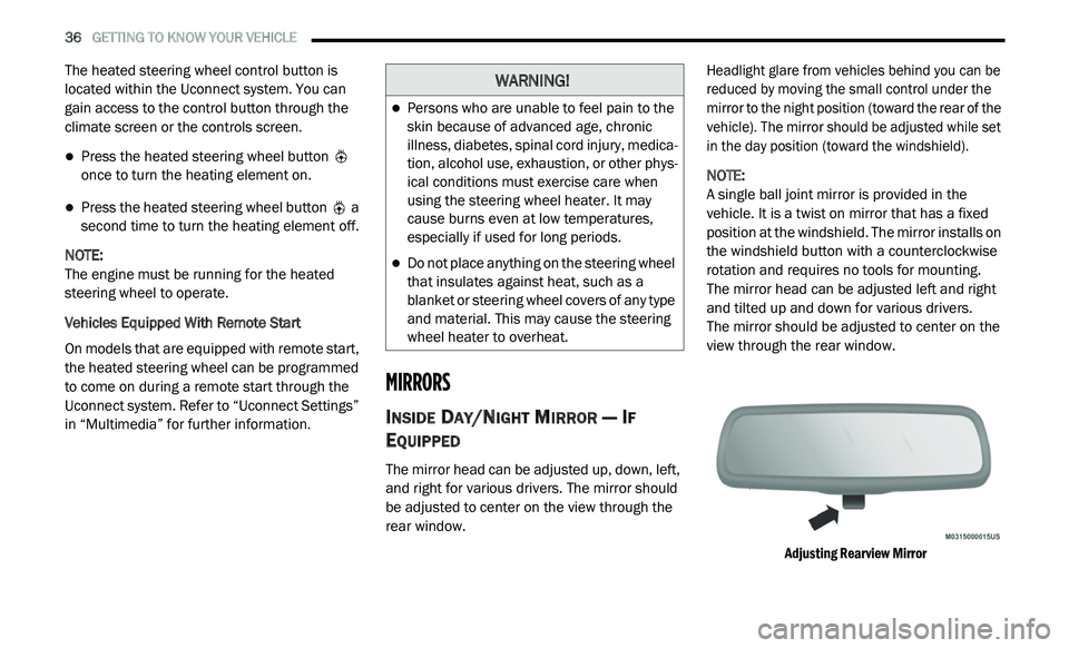
The mirror head can be adjusted up, down, left,
and right for various drivers. The mirror should
be adjusted to center on the view through the
rear window.
Headlight glare from vehicles behind you can be
r
e
duced by moving the small control under the
mirror to the night position (toward the rear of the
vehicle). The mirror should be adjusted while set
in the day position (toward the windshield).
NOTE:
A single ball joint mirror is provided in the
v e
hicle. It is a twist on mirror that has a fixed
position at the windshield. The mirror installs on
the windshield button with a counterclockwise
rotation and requires no tools for mounting.
The mirror head can be adjusted left and right
a n
d tilted up and down for various drivers.
The mirror should be adjusted to center on the
v i
ew through the rear window.
Adjusting Rearview Mirror
WARNING!
Persons who are unable to feel pain to the
skin because of advanced age, chronic
illness, diabetes, spinal cord injury, medica -
tion, alcohol use, exhaustion, or other phys -
ical conditions must exercise care when
u s
ing the steering wheel heater. It may
cause burns even at low temperatures,
especially if used for long periods.
Do not place anything on the steering wheel
that insulates against heat, such as a
blanket or steering wheel covers of any type
and material. This may cause the steering
wheel heater to overheat.
Page 43 of 396
GETTING TO KNOW YOUR VEHICLE 41
DAYTIME RUNNING LIGHTS (DRLS)
The Daytime Running Lights will turn on the first
time the vehicle is shifted out of PARK, and
remain on unless the parking brake is applied.
Upon returning to the PARK position, the DRLs
will turn off. DRLs will turn off when the ignition
is placed in the OFF position.
NOTE:
The DRLs can be turned on and off using the
Uconnect system, refer to “Uconnect Settings”
in “Multimedia” for further information.
On some vehicles, the Daytime Running
Lights may deactivate or reduce intensity on
one side of the vehicle (when a turn signal is
activated on that side), or on both sides of
the vehicle (when the hazard warning lights
are activated).
HIGH/LOW BEAM SWITCH
Push the multifunction lever away from you to
switch the headlights to high beam. Pull the
multifunction lever toward you to switch the
headlights back to low beam.
FLASH-TO-PASS
You can signal another vehicle with your
headlights by lightly pulling the multifunction
lever toward you. This will cause the high beam
headlights to turn on, and remain on, until the
lever is released.
AUTOMATIC HEADLIGHTS
This system automatically turns the headlights
on or off according to ambient light levels. To turn
the system on, rotate the headlight switch
counterclockwise to the AUTO position. When the
system is on, the headlight time delay feature is
also on. This means the headlights will stay on for
up to 90 seconds after you place the ignition in
the OFF position. The headlight time delay can be
programmed 0/30/60/90 seconds.
Refer to “Uconnect Settings” in “Multimedia”
fo
r further information.
To turn the automatic system off, move the
h e
adlight switch out of the AUTO position.
NOTE:
The engine must be running before the head -
lights will come on in the automatic mode.
HEADLIGHTS ON WITH WIPERS
(A
VAILABLE WITH AUTOMATIC
H
EADLIGHTS ONLY)
When this feature is active, the headlights will
turn on after the wipers are turned on if the
headlight switch is placed in the AUTO position
and programmable feature is set to on. In
addition, the headlights will turn off when the
wipers are turned off if they were turned on by
this feature.
NOTE:
The Headlights On with Wipers feature can be
t u
rned on or off using the Uconnect System.
Refer to “Uconnect Settings” in “Multimedia”
for further information.
HEADLIGHT TIME DELAY
This feature provides the safety of headlight
illumination for up to 90 seconds when leaving
your vehicle in an unlit area.
To activate the delay feature, place the ignition in
t h
e OFF position while the headlights are still on.
Then, turn off the headlights within 45 seconds.
The delay interval begins when the headlight
switch is turned off.
2
Page 46 of 396
44 GETTING TO KNOW YOUR VEHICLE
WIPERS AND WASHERS
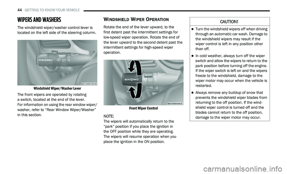
The windshield wiper/washer control lever is
located on the left side of the steering column.
Windshield Wiper/Washer Lever
The front wipers are operated by rotating
a switch, located at the end of the lever.
For information on using the rear window wiper/
w a
sher, refer to “Rear Window Wiper/Washer”
in this section.
WINDSHIELD WIPER OPERATION
Rotate the end of the lever upward, to the
first detent past the intermittent settings for
l o
w-speed wiper operation. Rotate the end of
the lever upward to the second detent past the
intermittent settings for high-speed wiper
operation.
Front Wiper Control
NOTE:
The wipers will automatically return to the
“ p
ark” position if you place the ignition in
the OFF position while they are operating.
The wipers will resume operation when you
p l
ace the ignition in the ON position.
CAUTION!
Turn the windshield wipers off when driving
through an automatic car wash. Damage to
the windshield wipers may result if the
wiper control is left in any position other
than off.
In cold weather, always turn off the wiper
switch and allow the wipers to return to the
park position before turning off the engine.
If the wiper switch is left on and the wipers
freeze to the windshield, damage to the
wiper motor may occur when the vehicle is
restarted.
Always remove any buildup of snow that
prevents the windshield wiper blades from
returning to the off position. If the wind -
shield wiper control is turned off and the
b la
des cannot return to the off position,
damage to the wiper motor may occur.
Page 48 of 396
46 GETTING TO KNOW YOUR VEHICLE
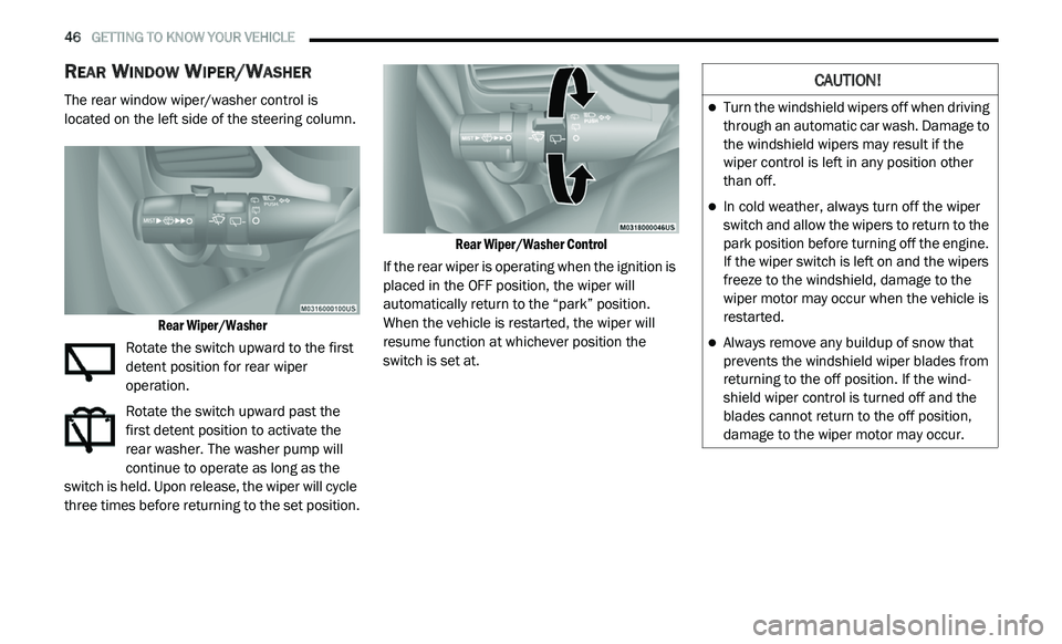
REAR WINDOW WIPER/WASHER
The rear window wiper/washer control is
located on the left side of the steering column.
Rear Wiper/Washer
Rotate the switch upward to the first
detent position for rear wiper
o p
eration.
Rotate the switch upward past the
first detent position to activate the
r e
ar washer. The washer pump will
continue to operate as long as the
switch is held. Upon release, the wiper will cycle
three times before returning to the set position.
Rear Wiper/Washer Control
If the rear wiper is operating when the ignition is
p l
aced in the OFF position, the wiper will
automatically return to the “park” position.
When the vehicle is restarted, the wiper will
resume function at whichever position the
switch is set at.
CAUTION!
Turn the windshield wipers off when driving
through an automatic car wash. Damage to
the windshield wipers may result if the
wiper control is left in any position other
than off.
In cold weather, always turn off the wiper
switch and allow the wipers to return to the
park position before turning off the engine.
If the wiper switch is left on and the wipers
freeze to the windshield, damage to the
wiper motor may occur when the vehicle is
restarted.
Always remove any buildup of snow that
prevents the windshield wiper blades from
returning to the off position. If the wind -
shield wiper control is turned off and the
b la
des cannot return to the off position,
damage to the wiper motor may occur.
Page 73 of 396
GETTING TO KNOW YOUR VEHICLE 71
NOTE:
It is not necessary to move the temperature
settings for cold or hot vehicles. The system
automatically adjusts the temperature,
mode, and blower speed to provide comfort
as quickly as possible.
The temperature can be displayed in U.S. or
Metric units by selecting the US/Metric customer
programmable feature. Refer to the “Uconnect
Settings” in “Multimedia” for further information.
To provide you with maximum comfort in the
Automatic mode during cold start-ups, the blower
fan remains on low until the engine warms up.
The blower will increase in speed and transition
into Auto mode.
Manual Operation Override
This system offers a full complement of manual
override features. The AUTO symbol in the front
ATC display will be turned off when the system
is being used in the manual mode.
OPERATING TIPS
NOTE:
Refer to the chart at the end of this section for
s u
ggested control settings for various weather
conditions.
Summer Operation
The engine cooling system must be protected
with a high-quality antifreeze coolant to provide
proper corrosion protection and to protect
against engine overheating. OAT coolant
(conforming to MS.90032) is recommended.
Refer to “Fluids And Lubricants” in “Technical
Specifications” for proper coolant selection.
Winter Operation
To ensure the best possible heater and defroster
performance, make sure the engine cooling
system is functioning properly and the proper
amount, type, and concentration of coolant is
used. Refer to “Fluids And Lubricants” in
“Technical Specifications” for proper coolant
selection. Use of the air Recirculation mode
during Winter months is not recommended,
because it may cause window fogging.
Vacation/Storage
Before you store your vehicle, or keep it out of
service (i.e., vacation) for two weeks or more, run
the air conditioning system at idle for about five
minutes, in fresh air with the blower setting on high.
This will ensure adequate system lubrication to
minimize the possibility of compressor damage
when the system is started again.
Window Fogging
Vehicle windows tend to fog on the inside in
mild, rainy, and/or humid weather. To clear the
windows, select Defrost or Mix mode and
increase the front blower speed. Do not use the
Recirculation mode without A/C for long
periods, as fogging may occur.
CAUTION!
Failure to follow these cautions can cause
damage to the heating elements:
Use care when washing the inside of the
rear window. Do not use abrasive window
cleaners on the interior surface of the
window. Use a soft cloth and a mild
washing solution, wiping parallel to the
heating elements. Labels can be peeled off
after soaking with warm water.
Do not use scrapers, sharp instruments, or
abrasive window cleaners on the interior
surface of the window.
Keep all objects a safe distance from the
window.
2
Page 83 of 396
GETTING TO KNOW YOUR VEHICLE 81
Programming A Rolling Code
For programming garage door openers that
were manufactured after 1995:
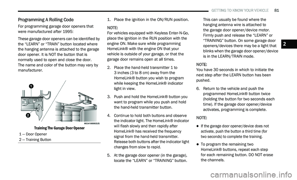
These garage door openers can be identified by
th
e “LEARN” or “TRAIN” button located where
the hanging antenna is attached to the garage
door opener. It is NOT the button that is
normally used to open and close the door.
The name and color of the button may vary by
m a
nufacturer.
Training The Garage Door Opener
1. P
lace the ignition in the ON/RUN position.
N
OTE:
For vehicles equipped with Keyless Enter-N-Go,
p l
ace the ignition in the RUN position with the
engine ON. Make sure while programming
HomeLink® with the engine ON that your
vehicle is outside of your garage, or that the
garage door remains open at all times.
2. P lace the hand-held transmitter 1 to
3
inches (3 to 8 cm) away from the
H o
meLink® button you wish to program
while keeping the HomeLink® indicator
light in view.
3. Push and hold the HomeLink® button you w
ant to program while you push and hold
the hand-held transmitter button.
4. C ontinue to hold both buttons and observe
t
he indicator light. The HomeLink® indicator
will flash slowly and then rapidly after
HomeLink® has received the frequency
signal from the hand-held transmitter.
Release both buttons after the indicator light
changes from slow to rapid.
5. A t the garage door opener (in the garage),
l
ocate the “LEARN” or “TRAINING” button. This can usually be found where the
hanging antenna wire is attached to
the garage door opener/device motor.
F i
rmly push and release the “LEARN” or
“TRAINING” button. On some garage door
openers/devices there may be a light that
blinks when the garage door opener/device
is in the LEARN/TRAIN mode.
NOTE:
You have 30 seconds in which to initiate the
n e
xt step after the LEARN button has been
pushed.
6. R eturn to the vehicle and push the
p
rogrammed HomeLink® button twice
(holding the button for two seconds each
time). If the garage door opener/device
activates, programming is complete.
NOTE:
If the garage door opener/device does not
activate, push the button a third time (for
two seconds) to complete the training.
To program the remaining two
HomeLink® buttons, repeat each step
for each remaining button. DO NOT erase
the channels.
1 — Door Opener
2 — Training Button
2
Page 84 of 396
82 GETTING TO KNOW YOUR VEHICLE
Programming A Non-Rolling Code
For programming garage door openers
manufactured before 1995:
1. P lace the ignition in the ON/RUN position.
N
OTE:
For vehicles equipped with Keyless Enter-N-Go,
p l
ace the ignition in the RUN position with the
engine on. Make sure while programming
HomeLink® with the engine on that your vehicle
is outside of your garage, or that the garage
door remains open at all times.
2. P lace the hand-held transmitter 1 to 3
inches
(3 to 8 cm) away from the HomeLink® button
y o
u wish to program while keeping the
HomeLink® indicator light in view.
3. P ush and hold the HomeLink® button you
w
ant to program while you push and hold
the hand-held transmitter button.
4. C ontinue to hold both buttons and observe
t
he indicator light. The HomeLink®
indicator will flash slowly and then rapidly
after HomeLink® has received the
frequency signal from the hand-held
transmitter. Release both buttons after the
indicator light changes from slow to rapid. 5. P
ush and hold the programmed
H
omeLink® button and observe the
indicator light.
NOTE:
If the indicator light stays on constantly,
programming is complete and the garage
door/device should activate when the
HomeLink® button is pushed.
To program the two remaining HomeLink®
buttons, repeat each step for each remaining
button. DO NOT erase the channels.
CANADIAN/GATE OPERATOR
P
ROGRAMMING
For programming transmitters in Canada/
United States that require the transmitter
signals to “time-out” after several seconds of
transmission:
Canadian radio frequency laws require
t r
ansmitter signals to time-out (or quit) after
several seconds of transmission, which may not
be long enough for HomeLink® to pick up the
signal during programming. Similar to this
Canadian law, some U.S. gate operators are
designed to time-out in the same manner. It may be helpful to unplug the device during the
c
y
cling process to prevent possible overheating
of the garage door or gate motor.
1. P lace the ignition in the ON/RUN position.
N
OTE:
For vehicles equipped with Keyless Enter-N-Go,
p l
ace the ignition in the ON/RUN position with
the engine on. Make sure while programming
HomeLink® with the engine on that your vehicle
is outside of your garage, or that the garage
door remains open at all times.
2. P lace the hand-held transmitter 1 to
3
inches (3 to 8 cm) away from the
H o
meLink® button you wish to program
while keeping the HomeLink® indicator
light in view.
3. Continue to push and hold the HomeLink® b
utton while you push and release (“cycle”) your
hand-held transmitter every two seconds until
HomeLink® has successfully accepted the
frequency signal. The indicator light will flash
slowly and then rapidly when fully trained.
Page 91 of 396
GETTING TO KNOW YOUR VEHICLE 89
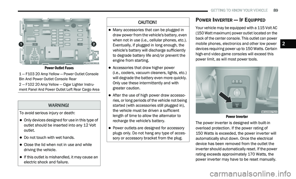
Power Outlet Fuses
POWER INVERTER — IF EQUIPPED
Your vehicle may be equipped with a 115 Volt AC
(150 Watt maximum) power outlet located on the
back of the center console. This outlet can power
mobile phones, electronics and other low power
devices requiring power up to 150 Watts. Certain
high-end video game consoles will exceed this
power limit, as will most power tools.
Power Inverter
The power inverter is designed with built-in
o v
erload protection. If the power rating of
150 Watts is exceeded, the power inverter will
a u
tomatically shut down. Once the electrical
device has been removed from the outlet the
inverter should automatically reset. If the power
rating exceeds approximately 170 Watts, the
power inverter may have to be reset manually.
1 — F103 20 Amp Yellow — Power Outlet Console
Bin And Power Outlet Console Rear
2 — F102 20 Amp Yellow — Cigar Lighter Instru -
ment Panel And Power Outlet Left Rear Cargo Area
WARNING!
To avoid serious injury or death:
Only devices designed for use in this type of
outlet should be inserted into any 12 Volt
outlet.
Do not touch with wet hands.
Close the lid when not in use and while
driving the vehicle.
If this outlet is mishandled, it may cause an
electric shock and failure.
CAUTION!
Many accessories that can be plugged in
draw power from the vehicle's battery, even
when not in use (i.e., cellular phones, etc.).
Eventually, if plugged in long enough, the
vehicle's battery will discharge sufficiently
to degrade battery life and/or prevent the
engine from starting.
Accessories that draw higher power
(i.e., coolers, vacuum cleaners, lights, etc.)
w i
ll degrade the battery even more quickly.
Only use these intermittently and with
greater caution.
After the use of high power draw accesso -
ries, or long periods of the vehicle not being
s t
arted (with accessories still plugged in),
the vehicle must be driven a sufficient
length of time to allow the alternator to
recharge the vehicle's battery.
Power outlets are designed for accessory
plugs only. Do not hang any type of acces -
sory or accessory bracket from the plug.
2
Page 96 of 396
94 GETTING TO KNOW YOUR INSTRUMENT PANEL
INSTRUMENT CLUSTER DESCRIPTIONS
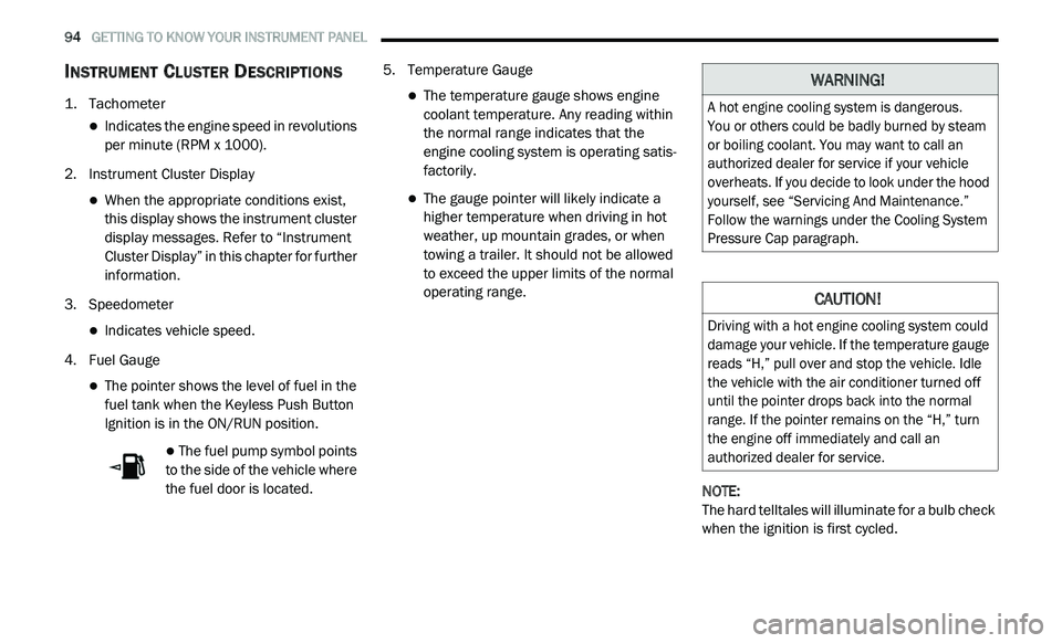
1. Tachometer
Indicates the engine speed in revolutions
per minute (RPM x 1000).
2. I nstrument Cluster Display
When the appropriate conditions exist,
this display shows the instrument cluster
display messages. Refer to “Instrument
Cluster Display” in this chapter for further
information.
3. S peedometer
Indicates vehicle speed.
4. F uel Gauge
The pointer shows the level of fuel in the
fuel tank when the Keyless Push Button
Ignition is in the ON/RUN position.
The fuel pump symbol points
to the side of the vehicle where
t h
e fuel door is located. 5. T
emperature Gauge
The temperature gauge shows engine
coolant temperature. Any reading within
the normal range indicates that the
engine cooling system is operating satis
-
factorily.
The gauge pointer will likely indicate a
higher temperature when driving in hot
weather, up mountain grades, or when
towing a trailer. It should not be allowed
to exceed the upper limits of the normal
operating range.
NOTE:
The hard telltales will illuminate for a bulb check
w h
en the ignition is first cycled.
WARNING!
A hot engine cooling system is dangerous.
You or others could be badly burned by steam
o r
boiling coolant. You may want to call an
authorized dealer for service if your vehicle
overheats. If you decide to look under the hood
yourself, see “Servicing And Maintenance.”
Follow the warnings under the Cooling System
Pressure Cap paragraph.
CAUTION!
Driving with a hot engine cooling system could
damage your vehicle. If the temperature gauge
reads “H,” pull over and stop the vehicle. Idle
the vehicle with the air conditioner turned off
until the pointer drops back into the normal
range. If the pointer remains on the “H,” turn
the engine off immediately and call an
authorized dealer for service.