check engine DODGE JOURNEY 2020 Owners Manual
[x] Cancel search | Manufacturer: DODGE, Model Year: 2020, Model line: JOURNEY, Model: DODGE JOURNEY 2020Pages: 396, PDF Size: 25.53 MB
Page 6 of 396
4
SAFETY TIPS ...................................................... 154
Transporting Passengers .. ........................154
Exhaust Gas . . .............................................154
Safety Checks You Should Make Inside
The Vehicle . .
..............................................155
Periodic Safety Checks You Should
Make Outside The Vehicle . .
...................... 156
STARTING AND OPERATING
STARTING THE ENGINE .................................... 157
Automatic Transmission .. .........................157
Normal Starting . . .......................................158
Keyless Enter-N-Go — Ignition . . .................158
Cold Weather Operation
(Below –22°F Or −30°C) . .
.......................159
If Engine Fails To Start . . ............................ 159
After Starting . . ............................................159
ENGINE BLOCK HEATER — IF EQUIPPED . . ...... 159
ENGINE BREAK-IN RECOMMENDATIONS .. .... 160
PARKING BRAKE .. ............................................ 160
AUTOMATIC TRANSMISSION.. .......................... 161
Ignition Park Interlock .. .............................162
Brake/Transmission Shift Interlock
System . ......................................................162
F
our-Speed Automatic Transmission . . .....163
Gear Ranges . . ...........................................163
POWER STEERING . . ........................................... 168
Power Steering Fluid Check .. ....................168SPEED CONTROL — IF EQUIPPED .
.
................. 168
To Activate.................................................. 169
T o Set A Desired Speed. . ........................... 169
To Vary The Speed Setting . . ...................... 169
To Accelerate For Passing . . ....................... 170
To Resume Speed . . ................................... 170
To Deactivate . . ........................................... 171
PARKSENSE REAR PARK ASSIST . . ................. 171
ParkSense Sensors .. ................................. 171
ParkSense Display . . ................................... 172
ParkSense Warning Display . . .................... 173
Enabling And Disabling ParkSense . . ........ 173
Service The ParkSense Rear Park
Assist System . .
........................................... 173
Cleaning The ParkSense System. . ............ 174
ParkSense System Usage Precautions . . .. 174
PARKVIEW REAR BACK UP CAMERA. . ............175
REFUELING THE VEHICLE .. ................................ 176
Loose Fuel Filler Cap Message .. ............... 177
VEHICLE LOADING . . ..........................................177
Vehicle Certification Label .. ...................... 177
Gross Vehicle Weight Rating (GVWR) . . ..... 178
Gross Axle Weight Rating (GAWR) . . ......... 178
Overloading . . .............................................. 178
Loading . ..................................................... 178 T RAILER TOWING .
.
............................................ 178
Common Towing Definitions .. ................... 178
Trailer Hitch Classification . . ...................... 180
Trailer Towing Weights (Maximum Trailer
Weight Ratings) . .
....................................... 181
Trailer And Tongue Weight . . ..................... 181
Towing Requirements . . ............................ 182
Towing Tips . . ............................................. 184
RECREATIONAL TOWING (BEHIND
MOTORHOME, ETC.) . .
....................................... 186
Towing This Vehicle Behind Another
Vehicle . ....................................................... 186
D
RIVING TIPS . . ................................................... 187
Driving On Slippery Surfaces .. ................. 187
Driving Through Water . . ........................... 187
IN CASE OF EMERGENCY
HAZARD WARNING FLASHERS ...................... 189
BULB REPLACEMENT ........................................ 189
Replacement Bulbs .. ................................ 189
Replacing Exterior Bulbs . . ......................... 191
FUSES . ................................................................. 193
I nterior Fuses .. .......................................... 193
Underhood Fuses (Power Distribution
Center) . ...................................................... 196
Page 7 of 396
5
JACKING AND TIRE CHANGING........................ 199
Jack Location .. ...........................................199
Spare Tire Location And Removal . . ..........200
Preparations For Jacking. . .........................201
Jacking Instructions . . .................................201
Road Tire Installation . . ..............................205
Spare Tire Stowage. . ..................................206
JUMP STARTING ................................................ 2 0 6
Preparations For Jump Start .. ...................207
Jump Starting Procedure. . .........................208
IF YOUR ENGINE OVERHEATS . . ....................... 209
2.4L Engine — If Equipped .. ...................... 210
GEAR SELECTOR OVERRIDE . . .......................... 210
FREEING A STUCK VEHICLE .. ........................... 211
TOWING A DISABLED VEHICLE .. ...................... 212
Front-Wheel Drive (FWD) Models.. ............213
Tow Eye Usage — If Equipped . . ................213
ENHANCED ACCIDENT RESPONSE
SYSTEM (EARS) . .
............................................... 215
EVENT DATA RECORDER (EDR) .. ..................... 215
SERVICING AND MAINTENANCE
SCHEDULED SERVICING ................................... 216
Maintenance Plan.. ....................................217
ENGINE COMPARTMENT . . ................................ 220
2.4L Engine .. ..............................................220
Checking Oil Level . . ................................... 221
Adding Washer Fluid . . ...............................221
Maintenance-Free Battery . . ...................... 221
Pressure Washing . . ....................................222 DEALER SERVICE .
.
............................................222
Engine Oil .................................................. 223
E ngine Oil Filter . . ........................................ 224
Engine Air Cleaner Filter . . ......................... 224
Air Conditioner Maintenance . . ................. 224
Accessory Drive Belt Inspection . . ............. 225
Body Lubrication . . ...................................... 226
Windshield Wiper Blades . . ........................ 226
Exhaust System . . ...................................... 227
Cooling System . . ....................................... 228
Brake System . . .......................................... 232
Automatic Transmission. . .......................... 233
RAISING THE VEHICLE . . .....................................234
TIRES....................................................................234 T ire Safety Information .. ........................... 234
Tires — General Information . . .................. 242
Tire Types . .................................................. 246
S pare Tires — If Equipped . . ....................... 247
Wheel And Wheel Trim Care . . .................. 249
Tire Chains and Traction Devices . . ........... 250
Tire Rotation Recommendations . . ........... 251
DEPARTMENT OF TRANSPORTATION UNIFORM
TIRE QUALITY GRADES . .
...................................251
Treadwear .................................................. 251
T raction Grades . . ....................................... 251
Temperature Grades . . ............................... 252
BODYWORK . . ...................................................... 252
Protection From Atmospheric Agents..
..... 252
Body And Underbody Maintenance . . ........ 253
Preserving The Bodywork . . ........................ 253INTERIORS .
.
....................................................... 254
Seats And Fabric Parts .. ............................ 254
Plastic And Coated Parts. . ......................... 254
Leather Parts . . ........................................... 255
Glass Surfaces . . ........................................ 255
Cleaning The Cupholders . . ....................... 255
TECHNICAL SPECIFICATIONS
IDENTIFICATION DATA ...................................... 256
Vehicle Identification Number .. ................ 256
BRAKE SYSTEM . . ............................................... 256
WHEEL AND TIRE TORQUE
SPECIFICATIONS ..
.............................................. 257
Torque Specifications.. .............................. 257
FUEL REQUIREMENTS . . .................................... 257
Reformulated Gasoline .. .......................... 258
Materials Added To Fuel . . ......................... 258
Gasoline/Oxygenate Blends . . ................... 258
Do Not Use E-85 In Non-Flex Fuel
Vehicles . ..................................................... 259
C
NG And LP Fuel System Modifications . . 259
MMT In Gasoline. . ...................................... 259
Fuel System Cautions. . .............................. 259
Carbon Monoxide Warnings. . .................... 260
FLUID CAPACITIES . . ........................................... 261
FLUIDS AND LUBRICANTS .. .............................. 262
Engine ....................................................... 262
C hassis . ..................................................... 264
Page 19 of 396
GETTING TO KNOW YOUR VEHICLE 17
After placing the ignition in the ON/RUN position,
the vehicle security light will turn on for
three seconds for a bulb check. If the light
r e
mains on after the bulb check, it indicates
that there is a problem with the electronics.
In addition, if the light begins to flash after the
b u
lb check, it indicates that someone used an
invalid key fob to start the engine. Either of these
conditions will result in the engine being shut off
after two seconds.
If the vehicle security light turns on during
no
rmal vehicle operation (vehicle running for
longer than 10 seconds), it indicates that there
is a fault in the electronics. Should this occur,
have the vehicle serviced as soon as possible by
an authorized dealer.
All of the key fobs provided with your new
v e
hicle have been programmed to the vehicle
electronics.
KEY PROGRAMMING
Programming key fobs may be performed at an
authorized dealer.
REPLACEMENT KEYS
NOTE:
Only key fobs that are programmed to the
v e
hicle electronics can be used to start and
operate the vehicle. Once a key fob is
programmed to a vehicle, it cannot be
programmed to any other vehicle.
NOTE:
Duplication of key fobs may be performed at an
a u
thorized dealer. This procedure consists of
programming a blank key fob to the vehicle
electronics. A blank key fob is one that has
never been programmed. When having the Sentry Key Immobilizer system
s
e
rviced, bring all vehicle keys with you to an
authorized dealer.
GENERAL INFORMATION
The following regulatory statement applies to all
Radio Frequency (RF) devices equipped in this
vehicle:
This device complies with Part 15 of the FCC
R u
les and with Innovation, Science and
Economic Development Canada license-exempt
RSS standard(s). Operation is subject to the
following two conditions:
1. T his device may not cause harmful
i
nterference, and
2. T his device must accept any interference
r
eceived, including interference that may
cause undesired operation.CAUTION!
The Sentry Key Immobilizer system is not
compatible with some aftermarket remote
starting systems. Use of these systems may
result in vehicle starting problems and loss of
security protection.
CAUTION!
Always remove the key fobs from the
vehicle and lock all doors when leaving the
vehicle unattended.
For vehicles equipped with Keyless
Enter-N-Go — Ignition, always remember to
place the ignition in the OFF position.
2
Page 96 of 396
94 GETTING TO KNOW YOUR INSTRUMENT PANEL
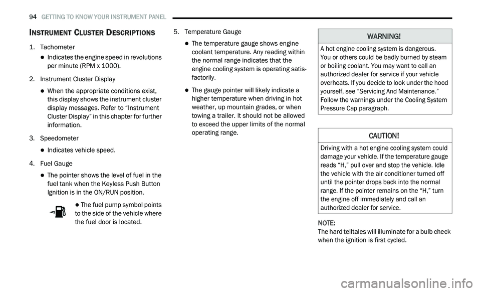
INSTRUMENT CLUSTER DESCRIPTIONS
1. Tachometer
Indicates the engine speed in revolutions
per minute (RPM x 1000).
2. I nstrument Cluster Display
When the appropriate conditions exist,
this display shows the instrument cluster
display messages. Refer to “Instrument
Cluster Display” in this chapter for further
information.
3. S peedometer
Indicates vehicle speed.
4. F uel Gauge
The pointer shows the level of fuel in the
fuel tank when the Keyless Push Button
Ignition is in the ON/RUN position.
The fuel pump symbol points
to the side of the vehicle where
t h
e fuel door is located. 5. T
emperature Gauge
The temperature gauge shows engine
coolant temperature. Any reading within
the normal range indicates that the
engine cooling system is operating satis
-
factorily.
The gauge pointer will likely indicate a
higher temperature when driving in hot
weather, up mountain grades, or when
towing a trailer. It should not be allowed
to exceed the upper limits of the normal
operating range.
NOTE:
The hard telltales will illuminate for a bulb check
w h
en the ignition is first cycled.
WARNING!
A hot engine cooling system is dangerous.
You or others could be badly burned by steam
o r
boiling coolant. You may want to call an
authorized dealer for service if your vehicle
overheats. If you decide to look under the hood
yourself, see “Servicing And Maintenance.”
Follow the warnings under the Cooling System
Pressure Cap paragraph.
CAUTION!
Driving with a hot engine cooling system could
damage your vehicle. If the temperature gauge
reads “H,” pull over and stop the vehicle. Idle
the vehicle with the air conditioner turned off
until the pointer drops back into the normal
range. If the pointer remains on the “H,” turn
the engine off immediately and call an
authorized dealer for service.
Page 103 of 396
GETTING TO KNOW YOUR INSTRUMENT PANEL 101
If the light remains on when the parking brake has
been disengaged, and the fluid level is at the full
mark on the master cylinder reservoir, it indicates a
possible brake hydraulic system malfunction or that
a problem with the Brake Booster has been
detected by the Anti-Lock Brake System (ABS) /
Electronic Stability Control (ESC) system. In this
case, the light will remain on until the condition has
been corrected. If the problem is related to the
brake booster, the ABS pump will run when applying
the brake, and a brake pedal pulsation may be felt
during each stop.
The dual brake system provides a reserve
br
aking capacity in the event of a failure to a
portion of the hydraulic system. A leak in either
half of the dual brake system is indicated by the
Brake Warning Light, which will turn on when
the brake fluid level in the master cylinder has
dropped below a specified level.
The light will remain on until the cause is
c o
rrected.
NOTE:
The light may flash momentarily during sharp
c o
rnering maneuvers, which change fluid level
conditions. The vehicle should have service
performed, and the brake fluid level checked. If brake failure is indicated, immediate repair is
n
e
cessary.
Vehicles equipped with the Anti-Lock Brake
S y
stem (ABS) are also equipped with Electronic
Brake Force Distribution (EBD). In the event of
an EBD failure, the Brake Warning Light will turn
on along with the ABS Light. Immediate repair to
the ABS system is required.
Operation of the Brake Warning Light can be
c h
ecked by turning the ignition switch from the
OFF position to the ON/RUN position. The light
should illuminate for approximately two
seconds. The light should then turn off unless
the parking brake is applied or a brake fault is
detected. If the light does not illuminate, have
the light inspected by an authorized dealer.
The light also will turn on when the parking
b r
ake is applied with the ignition switch in the
ON/RUN position. NOTE:
This light shows only that the parking brake is
a p
plied. It does not show the degree of brake
application.
Vehicle Security Warning Light — If
Equipped
This light will flash at a fast rate for
approximately 15 seconds when the
v e
hicle security alarm is arming, and
then will flash slowly until the vehicle
is disarmed.
Engine Coolant Temperature Warning
Light
This warning light warns of an
overheated engine condition. If the
e n
gine coolant temperature is too
high, this indicator will illuminate and
a single chime will sound. If the temperature
reaches the upper limit, a continuous chime will
sound for four minutes or until the engine is
able to cool, whichever comes first.
If the light turns on while driving, safely pull over
a n
d stop the vehicle. If the Air Conditioning (A/C)
system is on, turn it off. Also, shift the
transmission into NEUTRAL and idle the vehicle.
WARNING!
Driving a vehicle with the red brake light on is
dangerous. Part of the brake system may
have failed. It will take longer to stop the
vehicle. You could have a collision. Have the
vehicle checked immediately.
3
Page 104 of 396
102 GETTING TO KNOW YOUR INSTRUMENT PANEL
If the temperature reading does not return to
normal, turn the engine off immediately and call
for service.
Refer to “If Your Engine Overheats” in “In Case
Of
Emergency” for further information.
Transmission Temperature Warning Light
— If Equipped
This warning light will illuminate to
warn of a high transmission fluid
te
mperature. This may occur with
strenuous usage such as trailer
towing. If this light turns on, stop the vehicle and
run the engine at idle or slightly faster, with the
transmission in PARK or NEUTRAL, until the
light turns off. Once the light turns off, you may
continue to drive normally.
Battery Charge Warning Light
This warning light will illuminate when
the battery is not charging properly. If
i t
stays on while the engine is running,
there may be a malfunction with the
charging system. Contact an authorized dealer
as soon as possible.
This indicates a possible problem with the
e l
ectrical system or a related component.
Oil Pressure Warning Light
This warning light will illuminate to
indicate low engine oil pressure. If the
li
ght turns on while driving, stop the
vehicle, shut off the engine as soon as
possible, and contact an authorized dealer.
A chime will sound when this light turns on.
Do not operate the vehicle until the cause is
c o
rrected. This light does not indicate how
much oil is in the engine. The engine oil level
must be checked under the hood.
Electronic Throttle Control (ETC) Warning
Light
This warning light will illuminate to
indicate a problem with the Electronic
T h
rottle Control (ETC) system. If a
problem is detected while the vehicle is
running, the light will either stay on or flash
depending on the nature of the problem. Cycle the
ignition when the vehicle is safely and completely
stopped and the transmission is placed in the PARK
position. The light should turn off. If the light
remains on with the vehicle running, your vehicle
will usually be drivable; however, see an authorized
dealer for service as soon as possible.
NOTE:
This light may turn on if the accelerator and
b r
ake pedals are pressed at the same time.
If the light continues to flash when the vehicle is
r u
nning, immediate service is required and you
may experience reduced performance, an
elevated/rough idle, or engine stall and your
vehicle may require towing. The light will come
on when the ignition is placed in the ON/RUN or
ACC/ON/RUN position and remain on briefly as
a bulb check. If the light does not come on
during starting, have the system checked by an
authorized dealer.WARNING!
If you continue operating the vehicle when
the Transmission Temperature Warning Light
is illuminated you could cause the fluid to boil
over, come in contact with hot engine or
exhaust components and cause a fire.
CAUTION!
Continuous driving with the Transmission
Temperature Warning Light illuminated will
eventually cause severe transmission
damage or transmission failure.
Page 105 of 396
GETTING TO KNOW YOUR INSTRUMENT PANEL 103
Electric Power Steering Fault Warning
Light
This warning light will turn on when
there's a fault with the Electric Power
St
eering (EPS) system. Refer to
“Power Steering” in “Starting And
Operating” for further information.
Door Open Warning Light — If Equipped
This indicator will illuminate when a
door is ajar/open and not fully closed.
NOTE:
If the vehicle is moving, there will also be a
s i
ngle chime.
Liftgate Open Warning Light
This warning light will illuminate when
the liftgate is open.
NOTE:
If the vehicle is moving, there will also be a
s i
ngle chime.
YELLOW WARNING LIGHTS
Engine Check/Malfunction Indicator
Warning Light (MIL)
The Engine Check/Malfunction
Indicator Light (MIL) is a part of an
On
board Diagnostic System called
OBD II that monitors engine and
automatic transmission control systems. This
warning light will illuminate when the ignition
is in the ON/RUN position before engine start.
If the bulb does not come on when turning the
i g
nition switch from OFF to ON/RUN, have the
condition checked promptly. Certain conditions, such as a loose or missing
g
a
s cap, poor quality fuel, etc., may illuminate
the light after engine start. The vehicle should
be serviced if the light stays on through several
typical driving styles. In most situations, the
vehicle will drive normally and will not require
towing.
When the engine is running, the MIL may flash
t o
alert serious conditions that could lead to
immediate loss of power or severe catalytic
converter damage. The vehicle should be
serviced by an authorized dealer as soon as
possible if this occurs.
WARNING!
Continued operation with reduced assist
could pose a safety risk to yourself and
others. Service should be obtained as soon
as possible.
WARNING!
A malfunctioning catalytic converter, as
referenced above, can reach higher
temperatures than in normal operating
conditions. This can cause a fire if you drive
slowly or park over flammable substances
such as dry plants, wood, cardboard, etc.
This could result in death or serious injury to
t h
e driver, occupants or others.
3
Page 106 of 396
104 GETTING TO KNOW YOUR INSTRUMENT PANEL
Electronic Stability Control (ESC) Active
Warning Light — If Equipped
This warning light will indicate when the
Electronic Stability Control system is
Ac
tive. The “ESC Indicator Light” in the
instrument cluster will come on when the
ignition is placed in the ON/RUN or ACC/ON/RUN
position, and when ESC is activated. It should go out
with the engine running. If the “ESC Indicator Light”
comes on continuously with the engine running, a
malfunction has been detected in the ESC system. If
this warning light remains on after several ignition
cycles, and the vehicle has been driven several
miles (kilometers) at speeds greater than 30 mph
( 4
8 km/h), see an authorized dealer as soon as
p o
ssible to have the problem diagnosed and
corrected.
The “ESC OFF Indicator Light” and the “ESC
Indicator Light” come on momentarily each
time the ignition is placed in the ON/RUN or
ACC/ON/RUN position.
The ESC system will make buzzing or clicking
sounds when it is active. This is normal; the
sounds will stop when ESC becomes inactive.
This light will come on when the vehicle is in
an ESC event.
Electronic Stability Control (ESC) OFF
Warning Light — If Equipped
This warning light indicates the
Electronic Stability Control (ESC) is
o f
f.
Each time the ignition is turned to ON/RUN or
A C
C/ON/RUN, the ESC system will be on, even
if it was turned off previously.
Tire Pressure Monitoring System (TPMS)
Warning Light
The warning light switches on and a
message is displayed to indicate that
t h
e tire pressure is lower than the
recommended value and/or that slow
pressure loss is occurring. In these cases, optimal tire duration and fuel consumption may
not be guaranteed.
Should one or more tires be in the condition
m
e
ntioned above, the display will show the
indications corresponding to each tire.
Each tire, including the spare (if provided),
sh
ould be checked monthly when cold and
inflated to the inflation pressure recommended
by the vehicle manufacturer on the vehicle
placard or tire inflation pressure label. If your
vehicle has tires of a different size than the size
indicated on the vehicle placard or tire inflation
pressure label, you should determine the
proper tire inflation pressure for those tires.
CAUTION!
Prolonged driving with the Malfunction
Indicator Light (MIL) on could cause damage
to the vehicle control system. It also could
affect fuel economy and driveability. If the
MIL is flashing, severe catalytic converter
damage and power loss will soon occur.
Immediate service is required.
CAUTION!
Do not continue driving with one or more flat
tires as handling may be compromised. Stop
the vehicle, avoiding sharp braking and
steering. If a tire puncture occurs, repair
immediately using the dedicated tire repair
kit and contact an authorized dealer as soon
as possible.
Page 108 of 396
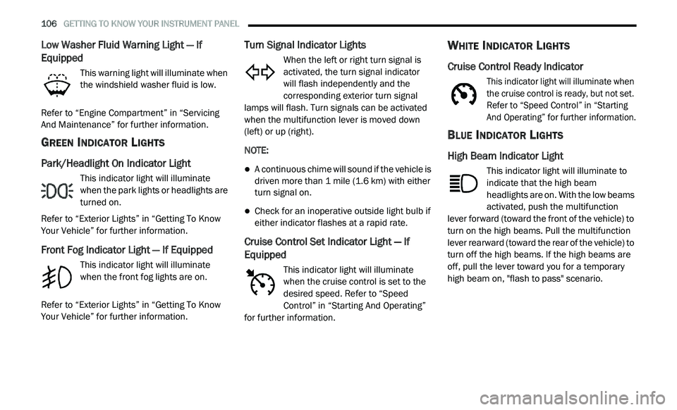
106 GETTING TO KNOW YOUR INSTRUMENT PANEL
Low Washer Fluid Warning Light — If
Equipped
This warning light will illuminate when
the windshield washer fluid is low.
Refer to “Engine Compartment” in “Servicing
A n
d Maintenance” for further information.
GREEN INDICATOR LIGHTS
Park/Headlight On Indicator Light
This indicator light will illuminate
when the park lights or headlights are
tu
rned on.
Refer to “Exterior Lights” in “Getting To Know
Y o
ur Vehicle” for further information.
Front Fog Indicator Light — If Equipped
This indicator light will illuminate
when the front fog lights are on.
Refer to “Exterior Lights” in “Getting To Know
Y o
ur Vehicle” for further information.
Turn Signal Indicator Lights
When the left or right turn signal is
activated, the turn signal indicator
will flash independently and the
c o
rresponding exterior turn signal
lamps will flash. Turn signals can be activated
when the multifunction lever is moved down
(left) or up (right).
NOTE:
A continuous chime will sound if the vehicle is
driven more than 1 mile (1.6 km) with either
t u
rn signal on.
Check for an inoperative outside light bulb if
either indicator flashes at a rapid rate.
Cruise Control Set Indicator Light — If
Equipped
This indicator light will illuminate
when the cruise control is set to the
d e
sired speed. Refer to “Speed
Control” in “Starting And Operating”
for further information.
WHITE INDICATOR LIGHTS
Cruise Control Ready Indicator
This indicator light will illuminate when
the cruise control is ready, but not set.
R e
fer to “Speed Control” in “Starting
And Operating” for further information.
BLUE INDICATOR LIGHTS
High Beam Indicator Light
This indicator light will illuminate to
indicate that the high beam
h e
adlights are on. With the low beams
activated, push the multifunction
lever forward (toward the front of the vehicle) to
turn on the high beams. Pull the multifunction
lever rearward (toward the rear of the vehicle) to
turn off the high beams. If the high beams are
off, pull the lever toward you for a temporary
high beam on, "flash to pass" scenario.
Page 110 of 396

108 GETTING TO KNOW YOUR INSTRUMENT PANEL
EMISSIONS INSPECTION AND
MAINTENANCE PROGRAMS
In some localities, it may be a legal requirement
to pass an inspection of your vehicle's
emissions control system. Failure to pass could
prevent vehicle registration.
For states that require an Inspection
a
nd Maintenance (I/M), this check
v e
rifies the “Malfunction Indicator
Light (MIL)” is functioning and is not
on when the engine is running, and that the
OBD II system is ready for testing.
Normally, the OBD II system will be ready. The
OB
D II system may not be ready if your vehicle
was recently serviced, recently had a depleted
battery or a battery replacement. If the OBD II
system should be determined not ready for the
I/M test, your vehicle may fail the test. Your vehicle has a simple ignition actuated test,
w
h
ich you can use prior to going to the test
station. To check if your vehicle's OBD II system
is ready, you must do the following:
1. Cycle the ignition switch to the ON position, b
ut do not crank or start the engine.
NOTE:
If you crank or start the engine, you will have to
s t
art this test over.
2. A s soon as you cycle the ignition switch to
t
he ON position, you will see the
“Malfunction Indicator Light (MIL)” symbol
come on as part of a normal bulb check.
3. Approximately 15 seconds later, one of two t
hings will happen:
The MIL will flash for about 10 seconds
and then return to being fully illuminated
until you turn OFF the ignition or start the
engine. This means that your vehicle's
OBD II system is not ready and you
should not proceed to the I/M station.
The MIL will not flash at all and will
remain fully illuminated until you place
the ignition in the off position or start the
engine. This means that your vehicle's
OBD II system is ready and you can
proceed to the I/M station.
If your OBD II system is not ready, y
ou should
see an authorized dealer or repair facility. If your
vehicle was recently serviced or had a battery
failure or replacement, you may need to do
nothing more than drive your vehicle as you
normally would in order for your OBD II system
to update. A recheck with the above test routine
may then indicate that the system is now ready.
Regardless of whether your vehicle's OBD II
s y
stem is ready or not, if the MIL is illuminated
during normal vehicle operation you should have
your vehicle serviced before going to the I/M
station. The I/M station can fail your vehicle
because the MIL is on with the engine running.