stop start DODGE JOURNEY 2020 Owners Manual
[x] Cancel search | Manufacturer: DODGE, Model Year: 2020, Model line: JOURNEY, Model: DODGE JOURNEY 2020Pages: 396, PDF Size: 25.53 MB
Page 11 of 396
9
GETTING TO KNOW YOUR VEHICLE
KEYS
KEY FOB
Your vehicle uses a keyless ignition system.
The ignition system consists of a key fob with
R e
mote Keyless Entry (RKE) and a START/STOP
push button ignition system. The Remote
Keyless Entry system consists of a key fob and
Keyless Enter-N-Go feature if equipped.
NOTE:
The key fob may not be found if it is located next
t o
a mobile phone, laptop or other electronic
device; these devices may block the key fob’s
wireless signal.
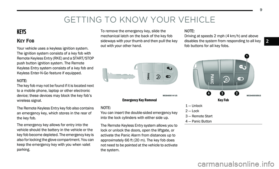
The Remote Keyless Entry key fob also contains
an
emergency key, which stores in the rear of
the key fob.
The emergency key allows for entry into the
v e
hicle should the battery in the vehicle or the
key fob become depleted. The emergency key is
also for locking the glove compartment. You can
keep the emergency key with you when valet
parking. To remove the emergency key, slide the
m
e
chanical latch on the back of the key fob
sideways with your thumb and then pull the key
out with your other hand.
Emergency Key Removal
NOTE:
You can insert the double-sided emergency key
in
to the lock cylinders with either side up.
The Remote Keyless Entry system allows you to
l o
ck or unlock the doors, open the liftgate, or
activate the Panic Alarm from distances up to
approximately 66 ft (20 m). The key fob does
n o
t need to be pointed at the vehicle to activate
the system. NOTE:
Driving at speeds 2 mph (4 km/h) and above
d i
sables the system from responding to all key
fob buttons for all key fobs.
Key Fob
1 — Unlock
2 — Lock
3 — Remote Start
4 — Panic Button
2
Page 12 of 396
10 GETTING TO KNOW YOUR VEHICLE
Backup Starting Method
In case the ignition switch does not change with
th
e push of a button, the key fob may have a low
or fully depleted battery.
In a situation of a low or fully depleted battery,
a backup method can be used to operate the
i g
nition switch. Put the nose side of the key fob
(side opposite of the emergency key) against
the START/STOP ignition button and push to
operate the ignition switch.
To Unlock The Doors And Liftgate
Push and release the unlock button on the key
fob once to unlock the driver's door or twice
within five seconds to unlock all doors and the
liftgate.
All doors can be programmed to unlock on the
f i
rst push of the unlock button. Refer to
“Uconnect Settings” in “Multimedia” for further
information.
NOTE:
If the vehicle is unlocked by a key fob, and no
d o
or is opened within 60 seconds, the vehicle
will re-lock and if equipped, the security alarm
will arm. The turn signal lights will flash twice to
a
c
knowledge the unlock signal. The illuminated
entry system will be activated.
1st Push Of Key Fob Unlock Button
This feature lets you program the system to
u n
lock either the driver's door or all doors on
the first push of the unlock button on the key
fob. To change the current setting, refer to
“Uconnect Settings” in “Multimedia” for further
information.
NOTE:
If the vehicle is equipped with Passive Entry,
r e
fer to “Keyless Enter-N-Go — Passive Entry” in
“Doors” in this chapter for further information.
Headlight Illumination On Approach
This feature activates the headlights for up
to 90 seconds when the doors are unlocked
w i
th the key fob. The time for this feature is
programmable, on vehicles equipped, through
Uconnect Settings. To change the current
setting, refer to “Uconnect Settings” in
“Multimedia” for further information.
To Lock The Doors And Liftgate
Push and release the lock button on the key fob
to lock all doors and liftgate.
The turn signal lights will flash and the horn will
c h
irp to acknowledge the signal. Refer to
“Uconnect Settings” in “Multimedia” for further
programmable information.
If the vehicle is equipped with Passive Entry,
r e
fer to “Keyless Enter-N-Go — Passive Entry” in
“Doors” in this chapter for further information.
Vehicles Equipped With Keyless Enter-N-Go —
P a
ssive Entry
If one or more doors are open, or the liftgate is
o p
en, the doors will lock. The doors will unlock
again automatically if the key is left inside the
passenger compartment, otherwise the doors
will stay locked.
Sound Horn With Lock
This feature will cause the horn to chirp
when the doors are locked with the key fob.
This feature can be turned on or turned off.
To change the current setting, refer to
“ U
connect Settings” in “Multimedia” for
further information.
Page 14 of 396
12 GETTING TO KNOW YOUR VEHICLE
4. To assemble the key fob case, snap the two
halves together.
Programming Additional Key Fobs
Programming the key fob may be performed by
an authorized dealer.
NOTE:
Once a key fob is programmed to a vehicle, it
c a
nnot be repurposed and reprogrammed to
another vehicle.
General Information
The following regulatory statement applies to all
Radio Frequency (RF) devices equipped in this
vehicle:
This device complies with Part 15 of the FCC
R u
les and with Innovation, Science and
Economic Development Canada license-exempt
RSS standard(s). Operation is subject to the
following two conditions:
1. T his device may not cause harmful
i
nterference, and
2. T his device must accept any interference
r
eceived, including interference that may
cause undesired operation. Le présent appareil est conforme aux CNR
d
`
Innovation, Science and Economic
Development applicables aux appareils radio
exempts de licence. L'exploitation est autorisée
aux deux conditions suivantes:
1. l 'appareil ne doit pas produire de
b
rouillage, et
2. l 'utilisateur de l'appareil doit accepter tout
b
rouillage radioélectrique subi, même si le
brouillage est susceptible d'en compro -
mettre le fonctionnement.
La operación de este equipo está sujeta a las
s i
guientes dos condiciones:
1. e s posible que este equipo o dispositivo no
c
ause interferencia perjudicial y
2. e ste equipo o dispositivo debe aceptar
c
ualquier interferencia, incluyendo la que
pueda causar su operación no deseada.
NOTE:
Changes or modifications not expressly
a p
proved by the party responsible for compli -
ance could void the user’s authority to operate
t h
e equipment.
IGNITION SWITCH
KEYLESS PUSH BUTTON IGNITION
This feature allows the driver to operate the
ignition with the push of a button as long as the
key fob is in the passenger compartment.
The Keyless Push Button Ignition has four
op
erating positions, three of which are labeled
and will illuminate when in position. The three
positions are OFF, ACC, and ON/RUN. The fourth
position is START. During START, RUN will
illuminate.
NOTE:
If the ignition switch does not change with the
p u
sh of a button, the key fob may have a low or
depleted battery. In this situation, a back up
method can be used to operate the ignition
switch. Put the nose side (side opposite of the
emergency key) of the key fob against the
START/STOP ignition button and push to
operate the ignition switch.
Page 15 of 396
GETTING TO KNOW YOUR VEHICLE 13
(Continued)
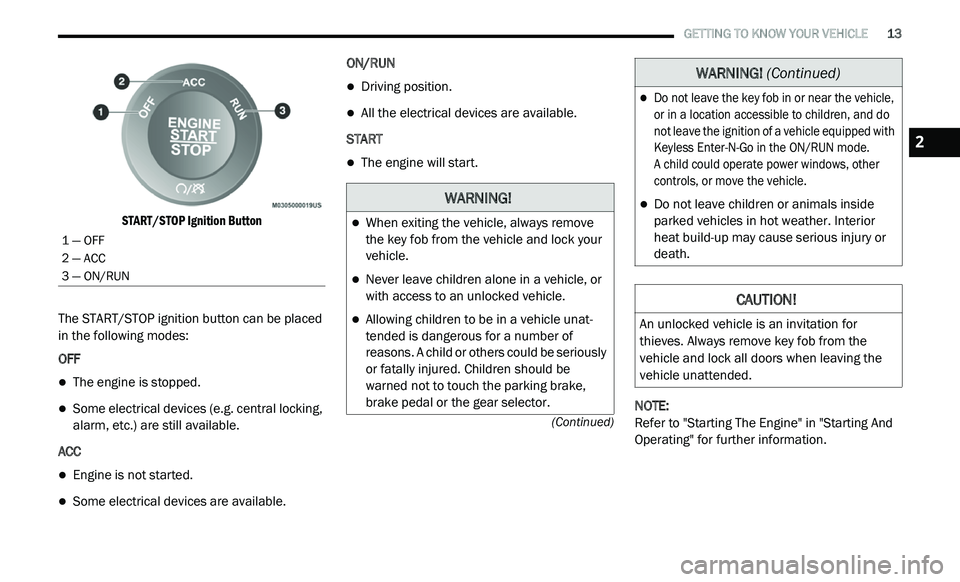
START/STOP Ignition Button
The START/STOP ignition button can be placed
i n
the following modes:
OFF
The engine is stopped.
Some electrical devices (e.g. central locking,
alarm, etc.) are still available.
ACC
Engine is not started.
Some electrical devices are available. ON/RUN
Driving position.
All the electrical devices are available.
START
The engine will start.
NOTE:
Refer to "Starting The Engine" in "Starting And
O p
erating" for further information.
1 — OFF
2 — ACC
3 — ON/RUN
WARNING!
When exiting the vehicle, always remove
the key fob from the vehicle and lock your
vehicle.
Never leave children alone in a vehicle, or
with access to an unlocked vehicle.
Allowing children to be in a vehicle unat -
tended is dangerous for a number of
r e
asons. A child or others could be seriously
or fatally injured. Children should be
warned not to touch the parking brake,
brake pedal or the gear selector.
Do not leave the key fob in or near the vehicle,
or in a location accessible to children, and do
not leave the ignition of a vehicle equipped with
Keyless Enter-N-Go in the ON/RUN mode.
A child could operate power windows, other
c o
ntrols, or move the vehicle.
Do not leave children or animals inside
parked vehicles in hot weather. Interior
heat build-up may cause serious injury or
death.
CAUTION!
An unlocked vehicle is an invitation for
thieves. Always remove key fob from the
vehicle and lock all doors when leaving the
vehicle unattended.
WARNING! (Continued)
2
Page 17 of 396
GETTING TO KNOW YOUR VEHICLE 15
REMOTE START ABORT MESSAGE
The following messages will appear in the
instrument cluster display if the vehicle fails to
remote start or exits remote start prematurely if
equipped with Remote Start:
Remote Start Cancelled — Door Open
Remote Start Cancelled — Hood Open
Remote Start Cancelled — Fuel Low
Remote Start Cancelled — L/Gate Open
Remote Start Disabled — Start Vehicle To
Reset The message stays active until the ignition is
p
l
aced in the ON/RUN position.
TO ENTER REMOTE START MODE
Push and release the remote start button on the
key fob twice within five seconds. The vehicle
doors will lock, the parking lights will flash and
the horn will chirp twice (if programmed). Then,
the engine will start and the vehicle will remain
in the Remote Start mode for a 15 minute cycle.
NOTE:
If an engine fault is present or fuel level is
low, the vehicle will start and then shut down
in 10 seconds.
The park lamps will turn on and remain on
during Remote Start mode.
For security, power window and power
sunroof operation (if equipped) are disabled
when the vehicle is in the Remote Start
mode.
The engine can be started two consecutive
times (two 15 minute cycles) with the key
f o
b. However, the ignition must be placed in
the ON/RUN position before you can repeat
the start sequence for a third cycle.
TO EXIT REMOTE START MODE
W
ITHOUT DRIVING THE VEHICLE
Push and release the remote start button one
time or allow the engine to run for the entire
15 minute cycle.
NOTE:
To avoid unintentional shutdowns, the system
wi
ll disable for two seconds after receiving a
valid Remote Start request.
TO EXIT REMOTE START MODE AND
D
RIVE THE VEHICLE
Before the end of 15 minute cycle, push and
re
lease the unlock button on the key fob to
unlock the doors and disarm the vehicle
security alarm (if equipped). Then, prior to the
end of the 15 minute cycle, push and release
t h
e START/STOP ignition button.
NOTE:
The message “Push Start Button” will appear in
t h
e instrument cluster display until you push the
START/STOP ignition button.
WARNING!
Do not start or run an engine in a closed
garage or confined area. Exhaust gas
contains Carbon Monoxide (CO) which is
odorless and colorless. Carbon Monoxide is
poisonous and can cause serious injury or
death when inhaled.
Keep key fobs away from children. Opera -
tion of the Remote Start System, windows,
d o
or locks or other controls could cause
serious injury or death.
2
Page 20 of 396
18 GETTING TO KNOW YOUR VEHICLE
Le présent appareil est conforme aux CNR
d`Innovation, Science and Economic
Development applicables aux appareils radio
exempts de licence. L'exploitation est autorisée
aux deux conditions suivantes:
1. l 'appareil ne doit pas produire de
b
rouillage, et
2. l 'utilisateur de l'appareil doit accepter tout
b
rouillage radioélectrique subi, même si le
brouillage est susceptible d'en compro -
mettre le fonctionnement.
La operación de este equipo está sujeta a las
s i
guientes dos condiciones:
1. e s posible que este equipo o dispositivo no
c
ause interferencia perjudicial y
2. e ste equipo o dispositivo debe aceptar
c
ualquier interferencia, incluyendo la que
pueda causar su operación no deseada.
NOTE:
Changes or modifications not expressly
a p
proved by the party responsible for compli -
ance could void the user’s authority to operate
t h
e equipment.
VEHICLE SECURITY ALARM — IF EQUIPPED
The vehicle security alarm monitors the vehicle
doors and liftgate for unauthorized entry and the
START/STOP ignition button for unauthorized
operation. While the vehicle security alarm is
armed, interior switches for door locks are
disabled. If something triggers the alarm, the
vehicle security alarm will provide the following
audible and visible signals: the horn will pulse,
the headlights will turn on, the park lamps and/or
turn signals will flash, and the vehicle security
light in the instrument cluster will flash.
TO ARM THE SYSTEM
Follow these steps to arm the vehicle security
alarm:
1. M ake sure the vehicle ignition system is
O
FF (refer to "Starting The Engine" in
"Starting And Operating" for further
information).
2. Perform one of the following methods to l
ock the vehicle:
Push lock on the interior power door lock
switch with the driver and/or passenger
door open.
Push the lock button on the exterior
Passive Entry Door Handle with a valid
key fob available in the same exterior
zone (refer to "Keyless Enter-N-Go —
Passive Entry" in “Doors” in this chapter
for further information).
Push the lock button on the key fob.
3. I f any doors are open, close them.
TO DISARM THE SYSTEM
The vehicle security alarm can be disarmed
using any of the following methods:
Push the unlock button on the key fob.
Grasp the Passive Entry Door Handle with a
valid key fob within 5 ft (1.5 m) of the passive
e n
try door handle (if equipped). Refer to
"Keyless Enter-N-Go — Passive Entry" in
“Doors” in this chapter for further information.
Cycle the vehicle ignition system out of the
OFF position.
For vehicles equipped with Keyless
Enter-N-Go — Passive Entry, push the
START/STOP ignition button (requires at
least one valid key fob in the vehicle).
Page 98 of 396
96 GETTING TO KNOW YOUR INSTRUMENT PANEL
Right Arrow Button
Push and release the ri
ght arrow
button for access to main menus or
s u
bmenus. Push and hold the right
arrow button for two seconds to
reset features.
Back Button
Push and release the BA
CK button
to scroll back to a previous menu.
OIL CHANGE DUE
Your vehicle is equipped with an engine oil
change indicator system. The “Oil Change Due”
message will appear in the instrument cluster
display for five seconds after a single chime has
sounded to indicate the next scheduled oil
change interval. The engine oil change indicator
system is duty cycle based, which means the
engine oil change interval may fluctuate
dependent upon your personal driving style. Unless reset, this message will continue to
d
i
splay each time you cycle the ignition to the
ON/RUN position. To turn off the message
temporarily, push and release the up arrow
button. To reset the oil change indicator system
(after performing the scheduled maintenance),
perform the following procedure:
1. W ithout pushing the brake pedal, push and
r
elease the ENGINE START/STOP button
and cycle the ignition to the ON/RUN
position (do not start the engine).
2. Fully push the accelerator pedal, slowly, t
hree times within 10 seconds.
3. W ithout pushing the brake pedal, push and
r
elease the ENGINE START/STOP button
once to return the ignition to the OFF/LOCK
position.
NOTE:
If the indicator message illuminates when you
s t
art the vehicle, the oil change indicator system
did not reset. If necessary, repeat this procedure.
INSTRUMENT CLUSTER DISPLAY
S
ELECTABLE MENU ITEMS
Push and release the up or down arrow button
until the desired Selectable Menu item is
displayed in the instrument cluster display.
Follow the Menu or submenu prompts as
d e
sired.
Fuel Economy
Push and release the up or down arrow button
until “Fuel Economy” displays highlighted in the
instrument cluster display and push the right
arrow button. The following Fuel Economy
functions will display in the instrument cluster
display:
Average Fuel Economy
Distance To Empty (DTE)
Instantaneous Fuel Economy
Page 101 of 396
GETTING TO KNOW YOUR INSTRUMENT PANEL 99
BATTERY SAVER ON/BATTERY SAVER
M
ODE MESSAGE — ELECTRICAL LOAD
R
EDUCTION ACTIONS — IF EQUIPPED
This vehicle is equipped with an Intelligent
Battery Sensor (IBS) to perform additional
monitoring of the electrical system and status
of the vehicle battery.
In cases when the IBS detects charging system
f a
ilure, or the vehicle battery conditions are
deteriorating, electrical load reduction actions
will take place to extend the driving time and
distance of the vehicle. This is done by reducing
power to or turning off non-essential electrical
loads.
Load reduction is only active when the engine is
r u
nning. It will display a message if there is a
risk of battery depletion to the point where the
vehicle may stall due to lack of electrical supply,
or will not restart after the current drive cycle.
When load reduction is activated, the message
“B
attery Saver On” or “Battery Saver Mode” will
appear in the instrument cluster.
These messages indicate the vehicle battery
h a
s a low state of charge and continues to lose
electrical charge at a rate that the charging
system cannot sustain. NOTE:
The charging system is independent from
load reduction. The charging system
performs a diagnostic on the charging
system continuously.
If the Battery Charge Warning Light is on it
may indicate a problem with the charging
system. Refer to “Battery Charge Warning
Light” in “Getting To Know Your Instrument
Panel” for further information.
The electrical loads that may be switched off
(if equipped), and vehicle functions which can
b e
affected by load reduction:
Heated Seat/Vented Seats/Heated Wheel
Rear Defroster And Heated Mirrors
HVAC System
115 Volts AC Power Inverter System
Audio and Telematics System
Loss of the battery charge may indicate one or
m o
re of the following conditions:
The charging system cannot deliver enough
electrical power to the vehicle system
because the electrical loads are larger than the capability of charging system. The
charging system is still functioning properly.
Excess vehicle electrical loads are turned on
(e.g. HVAC on max settings, exterior and inte
-
rior lights, overloaded power outlets +12 Volts,
1 1
5 Volts AC, USB ports) during certain driving
conditions (city driving, towing, frequent stop -
ping, etc.).
Installed options (additional lights, upfitter
electrical accessories, audio systems, alarms
and similar devices.
Unusual driving cycles (short trips separated
by long parking periods).
The vehicle was parked for an extended
period of time (weeks, months).
The battery was recently replaced and was
not charged completely.
The battery was discharged by an electrical
load left on when the vehicle was parked.
The battery was used for an extended period
with the engine not running to supply radio,
lights, chargers, +12 Volts portable appli -
ances like vacuum cleaners, game consoles
a n
d similar devices.
3
Page 104 of 396
102 GETTING TO KNOW YOUR INSTRUMENT PANEL
If the temperature reading does not return to
normal, turn the engine off immediately and call
for service.
Refer to “If Your Engine Overheats” in “In Case
Of
Emergency” for further information.
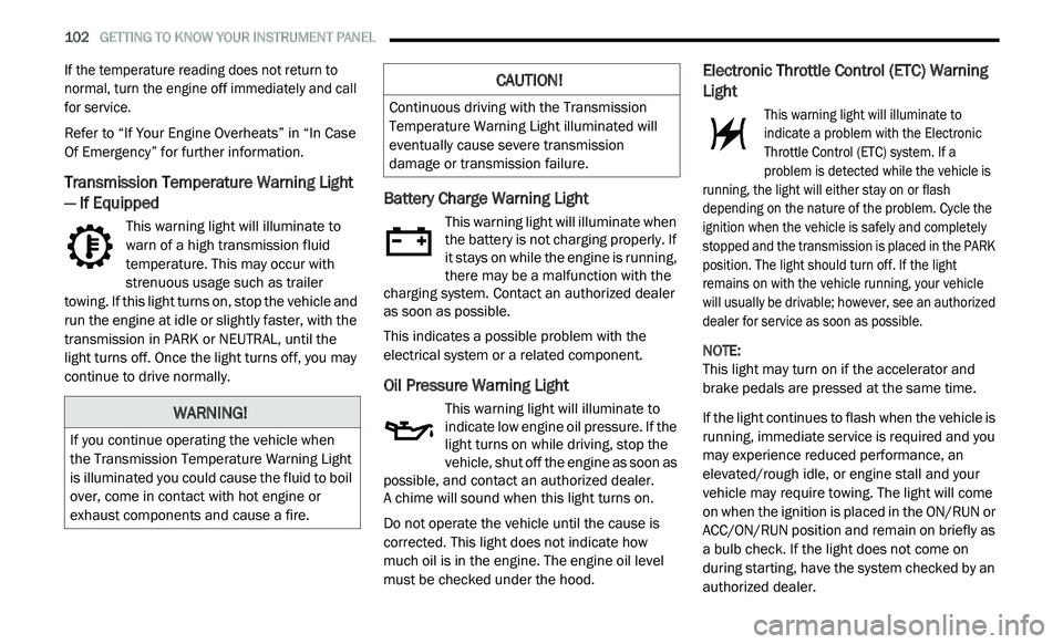
Transmission Temperature Warning Light
— If Equipped
This warning light will illuminate to
warn of a high transmission fluid
te
mperature. This may occur with
strenuous usage such as trailer
towing. If this light turns on, stop the vehicle and
run the engine at idle or slightly faster, with the
transmission in PARK or NEUTRAL, until the
light turns off. Once the light turns off, you may
continue to drive normally.
Battery Charge Warning Light
This warning light will illuminate when
the battery is not charging properly. If
i t
stays on while the engine is running,
there may be a malfunction with the
charging system. Contact an authorized dealer
as soon as possible.
This indicates a possible problem with the
e l
ectrical system or a related component.
Oil Pressure Warning Light
This warning light will illuminate to
indicate low engine oil pressure. If the
li
ght turns on while driving, stop the
vehicle, shut off the engine as soon as
possible, and contact an authorized dealer.
A chime will sound when this light turns on.
Do not operate the vehicle until the cause is
c o
rrected. This light does not indicate how
much oil is in the engine. The engine oil level
must be checked under the hood.
Electronic Throttle Control (ETC) Warning
Light
This warning light will illuminate to
indicate a problem with the Electronic
T h
rottle Control (ETC) system. If a
problem is detected while the vehicle is
running, the light will either stay on or flash
depending on the nature of the problem. Cycle the
ignition when the vehicle is safely and completely
stopped and the transmission is placed in the PARK
position. The light should turn off. If the light
remains on with the vehicle running, your vehicle
will usually be drivable; however, see an authorized
dealer for service as soon as possible.
NOTE:
This light may turn on if the accelerator and
b r
ake pedals are pressed at the same time.
If the light continues to flash when the vehicle is
r u
nning, immediate service is required and you
may experience reduced performance, an
elevated/rough idle, or engine stall and your
vehicle may require towing. The light will come
on when the ignition is placed in the ON/RUN or
ACC/ON/RUN position and remain on briefly as
a bulb check. If the light does not come on
during starting, have the system checked by an
authorized dealer.WARNING!
If you continue operating the vehicle when
the Transmission Temperature Warning Light
is illuminated you could cause the fluid to boil
over, come in contact with hot engine or
exhaust components and cause a fire.
CAUTION!
Continuous driving with the Transmission
Temperature Warning Light illuminated will
eventually cause severe transmission
damage or transmission failure.
Page 107 of 396
GETTING TO KNOW YOUR INSTRUMENT PANEL 105
As an added safety feature, your vehicle has
been equipped with a Tire Pressure Monitoring
System (TPMS) that illuminates a low tire
pressure telltale when one or more of your tires is
significantly under-inflated. Accordingly, when
the low tire pressure telltale illuminates, you
should stop and check your tires as soon as
possible, and inflate them to the proper pressure.
Driving on a significantly under-inflated tire
causes the tire to overheat and can lead to tire
failure. Under-inflation also reduces fuel
efficiency and tire tread life, and may affect the
vehicle’s handling and stopping ability.
Please note that the TPMS is not a substitute for
pr
oper tire maintenance, and it is the driver’s
responsibility to maintain correct tire pressure,
even if under-inflation has not reached the level
to trigger illumination of the TPMS low tire
pressure telltale.
Your vehicle has also been equipped with a TPMS
m a
lfunction indicator to indicate when the system is
not operating properly. The TPMS malfunction
indicator is combined with the low tire pressure
telltale. When the system detects a malfunction, the
telltale will flash for approximately one minute and
then remain continuously illuminated. This
sequence will continue upon subsequent vehicle start-ups as long as the malfunction exists. When
the malfunction indicator is illuminated, the system
may not be able to detect or signal low tire pressure
as intended. TPMS malfunctions may occur for a
variety of reasons, including the installation of
replacement or alternate tires or wheels on the
vehicle that prevent the TPMS from functioning
properly. Always check the TPMS malfunction
telltale after replacing one or more tires or wheels
on your vehicle to ensure that the replacement or
alternate tires and wheels allow the TPMS to
continue to function properly.
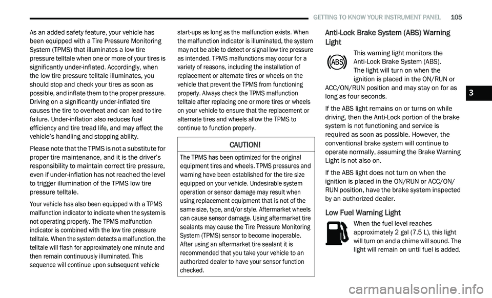
Anti-Lock Brake System (ABS) Warning
Light
This warning light monitors the
Anti-Lock Brake System (ABS).
The light will turn on when the
ignition is placed in the ON/RUN or
A C
C/ON/RUN position and may stay on for as
long as four seconds.
If the ABS light remains on or turns on while
d r
iving, then the Anti-Lock portion of the brake
system is not functioning and service is
required as soon as possible. However, the
conventional brake system will continue to
operate normally, assuming the Brake Warning
Light is not also on.
If the ABS light does not turn on when the
i g
nition is placed in the ON/RUN or ACC/ON/
RUN position, have the brake system inspected
by an authorized dealer.
Low Fuel Warning Light
When the fuel level reaches
approximately 2 gal (7.5 L), this light
w i
ll turn on and a chime will sound. The
light will remain on until fuel is added.
CAUTION!
The TPMS has been optimized for the original
equipment tires and wheels. TPMS pressures and
warning have been established for the tire size
equipped on your vehicle. Undesirable system
operation or sensor damage may result when
using replacement equipment that is not of the
same size, type, and/or style. Aftermarket wheels
can cause sensor damage. Using aftermarket tire
sealants may cause the Tire Pressure Monitoring
System (TPMS) sensor to become inoperable.
After using an aftermarket tire sealant it is
recommended that you take your vehicle to an
authorized dealer to have your sensor function
checked.
3