stop start DODGE MAGNUM SRT 2007 1.G User Guide
[x] Cancel search | Manufacturer: DODGE, Model Year: 2007, Model line: MAGNUM SRT, Model: DODGE MAGNUM SRT 2007 1.GPages: 380, PDF Size: 6.63 MB
Page 140 of 380
Loose Fuel Filler Cap
If the vehicle diagnostic system determines that the fuel
filler cap is loose, improperly installed, or damaged, a
ªCheck Gascapº message will display in the Electronic
Vehicle Information Center (EVIC). Tighten the fuel filler
cap properly and press the odometer reset button to turn
off the message. If the problem continues, the message
will appear the next time the vehicle is started.
A loose, improperly installed, or damaged fuel filler cap
may also turn on the Malfunction Indicator Light (MIL).
(See page 292 for more information.)
20. Brake System Warning Light
This light monitors various brake functions,
including brake fluid level and parking
brake application. If the brake light turns on,
it may indicate that the parking brake is
applied, that the brake fluid level is low, or that there
is a problem with the anti-lock brake system.
The dual brake system provides a reserve braking capac-
ity to a portion of the hydraulic system in the event of a
failure. Failure of either half of the dual brake system isindicated by the Brake Warning Light, which will turn on
when the brake fluid level in the master cylinder drops
below a specified level.
The light will remain on until the cause is corrected.
NOTE:The light may flash momentarily during sharp
cornering maneuvers, which change fluid level condi-
tions. The vehicle should have service performed, and
the brake fluid level checked.
Immediate repair is necessary if brake failure is indicated.
WARNING!
Driving a vehicle with the brake light on is danger-
ous. Part of the brake system may have failed. It will
take longer to stop the vehicle. You could have an
accident. Have the vehicle checked immediately.
Vehicles equipped with Anti-Lock brakes (ABS) are also
equipped with Electronic Brake Force Distribution (EBD).
Both the Brake Warning Light and the ABS Light will
UNDERSTANDING YOUR INSTRUMENT PANEL 139
4
Page 160 of 380
Operation Instructions - CD Mode
NOTE:
The ignition switch must be in the ON or ACC
position to operate the radio.
Inserting The Compact Disc (Single CD Player)
Gently insert one CD into the CD player with the CD
label facing up. The CD will automatically be pulled into
the CD Player and the CD icon will illuminate on the
radio display.
If the volume control is ON, the unit will switch to CD
mode and begin to play. The display will show the track
number and play time in minutes and seconds. Play will
begin at the start of track one.
NOTE:
²
On some vehicles, you may insert or eject a disc with
the radio or ignition switch OFF.
²If you insert a disc with the ignition ON and the radio
OFF, the CD will automatically be pulled into the CD
Player.
²This radio does not play discs with MP3 tracks.
SEEK Button (CD Mode)
Press the right side of the SEEK button for the next track
on the CD. Press the left side of the button to return to the
beginning of the current track, or return to the beginning
of the previous track if the CD is within the first 10
seconds of the current selection.
MUTE Button (CD Mode)
Press the MUTE button to cancel the sound from the
speakers.9MUTE9will display. Press the MUTE button a
second time and the sound from the speakers will return.
Rotating the volume control or turning OFF the ignition
will also return the sound from the speakers.
SCAN Button (CD Mode)
Press this button to play the first 10 seconds of each track.
To stop the scan function, press the button a second time.
EJECT Button (CD Mode)
Press this button and the disc will unload and
move to the entrance for easy removal. The
unit will switch to the last selected mode.
If you do not remove the disc within 15 seconds, it will be
reloaded. The radio mode will continue to appear.
UNDERSTANDING YOUR INSTRUMENT PANEL 159
4
Page 208 of 380
ENGINE BLOCK HEATER Ð IF EQUIPPED
The engine block heater warms engine coolant and
permits quicker starts in cold weather. Connect the cord
to a standard 110-115 volt AC electrical outlet with a
grounded, three-wire extension cord.
The engine block heater cord is routed under the hood on
the driver side of the vehicle. It has a removable cap that
is located on the driver side of the Integrated Power
Module.
WARNING!
Remember to disconnect the cord before driving.
Damage to the 110-115 volt electrical cord could
cause electrocution.
AUTOMATIC TRANSMISSION
CAUTION!
Damage to the transmission may occur if the follow-
ing precautions are not observed:
²Shift into PARK only after the vehicle has come to
a complete stop.
²Shift into or out of REVERSE only after the
vehicle has come to a complete stop and the
engine is at idle speed.
²Do not shift from REVERSE, PARK, or NEUTRAL
into any forward gear when the engine is above
idle speed.
²Before shifting into any gear, make sure your foot
is firmly on the brake pedal.
STARTING AND OPERATING 207
5
Page 212 of 380
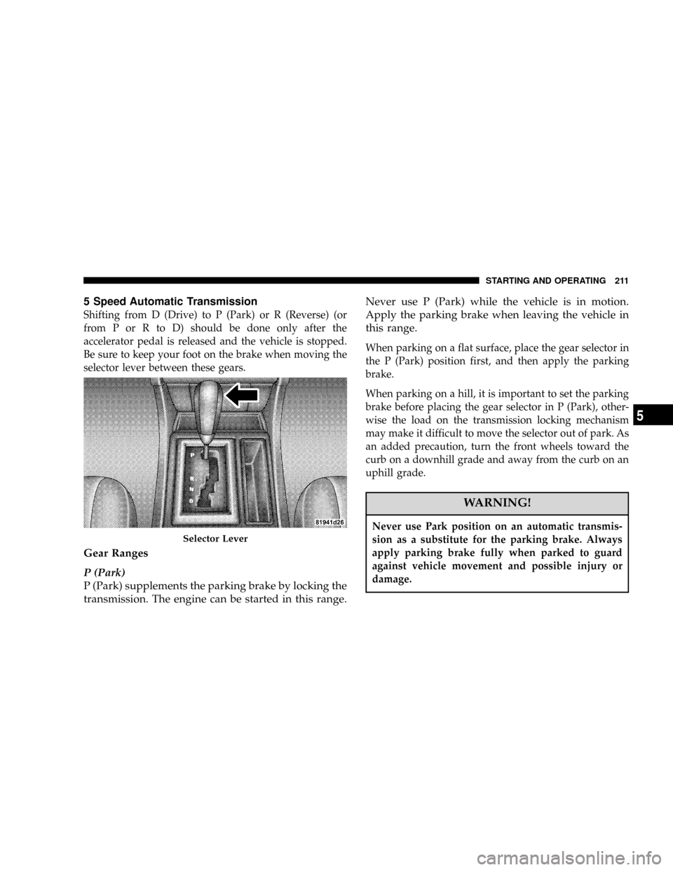
5 Speed Automatic Transmission
Shifting from D (Drive) to P (Park) or R (Reverse) (or
from P or R to D) should be done only after the
accelerator pedal is released and the vehicle is stopped.
Be sure to keep your foot on the brake when moving the
selector lever between these gears.
Gear Ranges
P (Park)
P (Park) supplements the parking brake by locking the
transmission. The engine can be started in this range.Never use P (Park) while the vehicle is in motion.
Apply the parking brake when leaving the vehicle in
this range.
When parking on a flat surface, place the gear selector in
the P (Park) position first, and then apply the parking
brake.
When parking on a hill, it is important to set the parking
brake before placing the gear selector in P (Park), other-
wise the load on the transmission locking mechanism
may make it difficult to move the selector out of park. As
an added precaution, turn the front wheels toward the
curb on a downhill grade and away from the curb on an
uphill grade.
WARNING!
Never use Park position on an automatic transmis-
sion as a substitute for the parking brake. Always
apply parking brake fully when parked to guard
against vehicle movement and possible injury or
damage.
Selector Lever
STARTING AND OPERATING 211
5
Page 213 of 380
The following indicators should be used to ensure that
you have engaged the selector lever into the P (Park)
position:
²When shifting into P (Park) move the lever all the way
forward until it stops, and is fully seated.
²Look at the shift indicator display on the instrument
panel to ensure it is in the P (Park) position.
CAUTION!
Damage to the shifter could result if the selector
lever is moved out of P (Park) before the ignition is
turned from the LOCK to ON position.
R (Reverse)
Shift into R (Reverse) gear only when the vehicle is
completely stopped.
N (Neutral)
No power is transmitted from the engine to the drive
axle. When the brakes are released, the vehicle can be
moved freely (pushed or towed). Do not engage N(Neutral) position while driving except to coast when
the vehicle is in danger of skidding (e.g., on icy roads).
The engine may be started in this range. Use this range
for starting your vehicle if it is moving or being towed.
CAUTION!
Coasting the vehicle, or driving for any other reason
with selector lever in NEUTRAL can result in trans-
mission damage.
WARNING!
Do not coast in N (Neutral) and never turn off the
ignition to coast down a hill. These are unsafe
practices that limit your response to changing traffic
or road conditions. You might lose control of the
vehicle and have an accident.
212 STARTING AND OPERATING
Page 215 of 380
Delayed Shifts in Cold Temperatures
During cold temperature operation, you may notice
delayed upshifts depending on engine and transmission
temperature as well as vehicle speed. This feature im-
proves warm up time of the engine and transmission to
achieve maximum efficiency.
Temporary Transmission Limp Home Mode
The transmission is monitored for abnormal conditions.
If a condition is detected that could result in transmission
damage, the transmission will engage Limp Home Mode.
If vehicle acceleration worsens, or the transmission no
longer shifts, the transmission is most likely operating in
the Limp Home Mode. In this mode, the transmission
will remain in the current gear until the vehicle is
brought to a stop. After the vehicle has stopped, P (Park),
R (Reverse), and N (Neutral) will continue to operate.
Second gear will operate in the D (Drive) shifter position.
The Malfunction Indicator Light may be illuminated.
A reset feature is available to allow the vehicle to be
driven to a dealer for service. To reset the transmission,
use the following procedure:
1. Stop the vehicle.2. Move the selector lever to the P (Park) position.
3. Turn off the engine.
4. Wait approximately 10 seconds.
5. Restart the engine.
6. Move the selector lever to the desired range. If the
problem is no longer detected, the transmission will
return to normal operation.
NOTE:Even if the transmission can be reset, we
recommend that you visit a dealer at your earliest
possible convenience. Your dealer has diagnostic equip-
ment to determine if the problem could recur.
Have the transmission checked at your authorized dealer
as soon as possible.
If the problem has been momentary, the transmission can
be reset to regain all forward gears.
Permanent Transmission Limp Home Mode
Permanent Limp Home Mode will be activated if the
transmission enters temporary Limp Home Mode three
214 STARTING AND OPERATING
Page 217 of 380
right for at least one second. The transmission will now
operate automatically, shifting between the five available
gears.
AutostickTGeneral Information
²
You can start out in first or second gear. The system
will ignore attempts to upshift at too low of a vehicle
speed.
²The transmission will automatically downshift to first
gear when coming to a stop.
²Starting out in second gear is helpful in snowy or icy
conditions.
²Avoid using speed control when Autosticktis en-
gaged.
²The transmission will not automatically shift up when
maximum engine speed is reached while Autosticktis
engaged.
²Transmission shifting will be more noticeable when
Autosticktis engaged.
DRIVING ON SLIPPERY SURFACES
Acceleration
Rapid acceleration on snow covered, wet, or other slip-
pery surfaces may cause the rear wheels to pull errati-
cally to the right or left. This phenomenon occurs when
there is a difference in the surface traction under the rear
(driving) wheels.
WARNING!
Rapid acceleration on slippery surfaces is danger-
ous. Unequal traction can cause sudden pulling of
the rear wheels. You could lose control of the vehicle
and possibly have an accident. Accelerate slowly and
carefully whenever there is likely to be poor traction
(ice, snow, wet mud, loose sand, etc.).
Traction
When driving on wet or slushy roads, it is possible for a
wedge of water to build up between the tire and road
surface. This is known as hydroplaning and may cause
216 STARTING AND OPERATING
Page 218 of 380
partial or complete loss of vehicle control and stopping
ability. To reduce this possibility, the following precau-
tions should be observed:
1. Slow down during rainstorms or when the roads are
slushy.
2. Slow down if road has standing water or puddles.
3. Replace tires when tread wear indicators first become
visible.
4. Keep tires properly inflated.
5. Maintain sufficient distance between your vehicle and
the vehicle in front to avoid a collision in a sudden stop.PARKING BRAKE
The parking brake should always be applied when the
driver is not in the vehicle.
WARNING!
Never use Park position on an automatic transmis-
sion as a substitute for the parking brake. Always
apply parking brake fully when parked to guard
against vehicle movement and possible injury or
damage.
When parking on a flat surface, place the gear selector in
the P (Park) position first, and then apply the parking
brake.
When parking on a hill, it is important to apply the
parking brake before placing the gear selector in P (Park),
otherwise the load on the transmission locking mecha-
nism may make it difficult to move the selector out of
park. As an added precaution, turn the front wheels
toward the curb on a downhill grade and away from the
curb on an uphill grade.
STARTING AND OPERATING 217
5
Page 220 of 380
BRAKE SYSTEM
Your vehicle is equipped with dual hydraulic
brake systems. If either of the two hydraulic
systems loses normal capability, the remaining
system will still function. There will be some
loss of overall braking effectiveness. This may be evident
by increased pedal travel during application, greater
pedal force required to slow or stop, and potential
activation of the Brake Warning Light.
In the event power assist is lost for any reason (for
example, repeated brake applications with the engine off)
the brakes will still function. The effort required to brake
the vehicle will be much greater than that required with
the power system operating.
Anti-Lock Brake System
The Anti-Lock Brake System provides increased vehicle
stability and brake performance under most braking
conditions. The system automatically ªpumpsº the
brakes during severe braking conditions to prevent
wheel lock-up.The electronic brake force distribution (EBD) prevents the
rear wheels from over-braking and provides greater
control of available braking forces applied to the rear
axle.
When the vehicle is driven over 7 mph (11 km/h), you
may also hear a slight clicking sound as well as some
related motor noises. These noises are the system per-
forming its self check cycle to ensure that the ABS system
is working properly. This self check occurs each time the
vehicle is started and accelerated past 7 mph (11 km/h).
ABS is activated during braking under certain road or
stopping conditions. ABS-inducing conditions can in-
clude ice, snow, gravel, bumps, railroad tracks, loose
debris, or panic stops.
STARTING AND OPERATING 219
5
Page 221 of 380
You also may experience the following when the brake
system goes into Anti-lock:
²The ABS motor running (it may continue to run for a
short time after the stop),
²the clicking sound of solenoid valves,
²brake pedal pulsations,
²and a slight drop or fall away of the brake pedal at the
end of the stop.
These are all normal characteristics of ABS.
WARNING!
²The Anti-Lock Brake System contains sophisticated
electronic equipment that may be susceptible to inter-
ference caused by improperly installed or high output
radio transmitting equipment. This interference can
cause possible loss of anti-lock braking capability. In-
stallation of such equipment should be performed by
qualified professionals.
²Pumping of the Anti-Lock Brakes will diminish their
effectiveness and may lead to an accident. Pumping
makes the stopping distance longer. Just press firmly on
your brake pedal when you need to slow down or stop.
²Anti-lock system (ABS) cannot prevent the natural laws
of physics from acting on the vehicle, nor can it increase
braking or steering efficiency beyond that afforded by
the condition of the vehicle brakes and tires or the
traction afforded.
²The ABS cannot prevent accidents, including those
resulting from excessive speed in turns, following an-
other vehicle too closely, or hydroplaning. Only a safe,
attentive, and skillful driver can prevent accidents.
²The capabilities of an ABS equipped vehicle must never
be exploited in a reckless or dangerous manner, which
could jeopardize the user's safety or the safety of others.
220 STARTING AND OPERATING