relay DODGE NEON 1997 1.G Wiring Diagrams Manual PDF
[x] Cancel search | Manufacturer: DODGE, Model Year: 1997, Model line: NEON, Model: DODGE NEON 1997 1.GPages: 256, PDF Size: 2.99 MB
Page 177 of 256

Downloaded from www.Manualslib.com manuals search engine 8
RELAY MIRROR
FOLDING
POWER
M
M
M
1
43
LEFT
MIRROR
34
15
M MM P90
18
LG/BK
P90
18
LG/BK
P90
18
LG/BK
9C231
9C205
P90
18
LG/BK
C21
POWER
MIRROR
SWITCH
6C1
P91
18
WT/BK
P91
18
WT/BK
P91
18
WT/BK
10C205
10C231
7C1 C18
5P95
18
DB/WT
P95
18
DB/WT
P95
18
DB/WT
P93
18
YL/BK
P93
18
YL/BK
P93
18
YL/BK
P99
18
GY
P99
18
GY
P99
18
GY
12 11 4
81112
P99
18
GY
P91
18
WT/BK
C143C1
P92
18
YLP94
18
WT/YL
66
6 RETRACT 4 LEFT
5 EXTEND 1 DOWN
2 UP
3 RIGHT
1
2
3
4 PTC
5
6PTC1
2
3
4 6 5
POWER POWER
3 RIGHT 2 UP
1 DOWN
5 EXTEND 4 LEFT
6 RETRACT MIRROR RIGHT
(8W-62-4)
(8W-62-2)
PL-RHD8W-62 POWER MIRRORS 8W - 62 - 3
PLR06202978W-1
Page 178 of 256

Downloaded from www.Manualslib.com manuals search engine 65 2
481
1
RIGHT
POWER
MIRROR LEFT
POWER
MIRROR
9C205
C2319
RUN F21
15A BREAKER CIRCUITHOLDER
FUSE
MIRROR
POWER
POWER
MIRROR
SWITCH
5 2
G203
P90
18
LG/BK
P90
18
LG/BK
P90
18
LG/BK
P90
18
LG/BK
F121
18
TN/BKF121
18
TN/BK
P110
18
OR
POWER
FOLDING
MIRROR
RELAY
Z8
18
BK/VT
Z8
14
BK/VT
Z8
18
BK/VT
S310
4C205
Z8 18BK/VT
(8W-62-3) (8W-62-3)
(8W-62-2)
(8W-15-6) (8W-11-10)
(8W-15-6)
8W - 62 - 4 8W-62 POWER MIRRORSPL-RHD
978W-1PLR06203
Page 179 of 256

Downloaded from www.Manualslib.com manuals search engine 8W-62 POWER MIRRORS
INDEX
page page
DESCRIPTION AND OPERATION
HELPFUL INFORMATION.................. 5POWER FOLDING MIRRORS............... 5
POWER MIRRORS....................... 5
DESCRIPTION AND OPERATION
POWER MIRRORS
Power for the power mirror switch is supplied on
circuit F121. This circuit is protected by a 15 amp
circuit breaker located in the right front door. Power
for the circuit breaker is supplied by circuit F21.
The F21 circuit is protected by a 30 amp circuit
breaker. This circuit breaker also supplies power to
the power windows.
The power mirror switch has a right and left posi-
tion. Moving the switch to either of these positions
changes the voltage path internal to the switch (ie.
changes polarity at the motors).
When the switch is moved to the RIGHT position
and mirror movement UP is selected, voltage is sup-
plied to the mirror on circuit P92 and the ground
path is supplied on circuit P90. The P90 circuit con-
nects from the mirror to the normally CLOSED con-
tacts in the mirror relay located in the right door.
When the right mirror DOWN movement is
selected voltage is supplied through the switch to cir-
cuit P110. The P110 circuit connects from the switch
to the power mirror relay located in the door, coil
side. Power on the coil side causes the contacts in the
relay to CLOSE connecting circuits F121 and P90.
The P90 circuit then supplies power to the DOWN
side of the motor. Ground for the motor is supplied
on circuit P92 back to the switch and then connects
to circuit Z8. The Z8 circuit connects from the switch
to its grounding point on the right instrument panel
center support.
If right door mirror movement LEFT is selected
voltage is supplied through the P94 circuit and the
ground is passed through circuit P91. When left mir-
ror RIGHT movement is selected the power and
ground are reversed.
When the switch is moved to the LEFT position
and mirror movement UP is selected, voltage is sup-
plied to the mirror on circuit P93 and the ground
path is supplied on circuit P90. The P90 circuit con-
nects from the mirror to the normally CLOSED con-
tacts in the mirror relay located in the right door.
When the left mirror DOWN movement is selected
voltage is supplied through the switch to circuit P110.
The P110 circuit connects from the switch to the powermirror relay located in the door, coil side. Power on the
coil side causes the contacts in the relay to CLOSE con-
necting circuits F121 and P90. The P90 circuit then
supplies power to the DOWN side of the motor. Ground
for the motor is supplied on circuit P93 back to the
switch and then connects to circuit Z8. The Z8 circuit
connects from the switch to its grounding point on the
right instrument panel center support.
If left door mirror movement LEFT is selected volt-
age is supplied through the P95 circuit and the
ground is passed through circuit P91. When left mir-
ror RIGHT movement is selected the power and
ground are reversed.
POWER FOLDING MIRRORS
Power for the power mirror switch is supplied on
circuit F121. This circuit is protected by a 15 amp
circuit breaker located in the right front door. Power
for the circuit breaker is supplied by circuit F21.
The F21 circuit is protected by a 30 amp circuit
breaker. This circuit breaker also supplies power to
the power windows.
When the operator selects mirrors RETRACT volt-
age is supplied on circuit F121 through the CLOSED
contacts in the switch to circuit P110. Circuit P110
connects to the power mirror relay coil side.
Voltage on the coil side of the relay causes the con-
tacts in the relay to CLOSE connecting circuits F121
and P90. The P90 circuit connects from the relay to
the power mirrors. Ground for the motors is supplied
on circuit P99 back to the power mirror switch. Inter-
nal to the switch the P99 circuit connects to the Z8
ground circuit.
When the operator selects the EXTEND function
power is supplied on circuit F121 through the
CLOSED contacts in the switch to circuit P99. The
P99 circuit connects to the power mirror motors.
Ground for the motors is supplied on circuit P90.
HELPFUL INFORMATION
²Check the 30 amp circuit breaker located behind
the fuse block
²Check the 15 amp circuit breaker located in the
right door
²Check the grounding point at the instrument
panel right center support
PL8W - 62 POWER MIRRORS 8W - 62 - 5
Page 189 of 256

Downloaded from www.Manualslib.com manuals search engine 8W-80 CONNECTOR PIN-OUTS
INDEX
page
SCHEMATICS AND DIAGRAMS........................................................... 1
Component Page
A/C Compressor Clutch................8W-80-4
A/C Cycling switch...................8W-80-4
A/C-Heater Blower Motor..............8W-80-4
A/C-Heater Control Switch.............8W-80-4
A/C High Pressure Switch..............8W-80-4
A/C Low Ptressure Switch..............8W-80-5
ABS Hydraulic Modulator..............8W-80-5
ABS Relay Box......................8W-80-5
Airbag Control Module................8W-80-5
Ash Receiver lamp...................8W-80-6
Back-Up Lamp Switch (MTX)...........8W-80-6
Battery Temperature Sensor............8W-80-6
Blower Motor Resister Block............8W-80-6
Brake Warning Lamp Switch...........8W-80-6
C101..............................8W-80-7
C102..............................8W-80-7
C103..............................8W-80-7
C105..............................8W-80-8
C108..............................8W-80-8
C160..............................8W-80-8
C161..............................8W-80-8
C203..............................8W-80-9
C205..............................8W-80-9
C206..............................8W-80-9
C225..............................8W-80-9
C230.............................8W-80-10
C231.............................8W-80-10
C241.............................8W-80-10
C301.............................8W-80-11
C303.............................8W-80-11
C309.............................8W-80-11
C315.............................8W-80-11
C323.............................8W-80-11
C324.............................8W-80-11
C325.............................8W-80-12
C340.............................8W-80-12
C341.............................8W-80-12
Camshaft Position Sensor.............8W-80-12
Clockspring........................8W-80-12
Clutch Pedal Position Switch (MTX).....8W-80-12
Controller Anti-Lock Brake............8W-80-13
Crankshaft Position Sensor............8W-80-14
Data Link Connector.................8W-80-14
Dome Lamp........................8W-80-14
Downstream Heated Oxygen Sensor.....8W-80-15Component Page
Driver Side Airbag..................8W-80-15
Duty Cycle Evap/Purge Solenoid........8W-80-15
EGR Transducer solenoid.............8W-80-15
Engine Coolant Temperature
Sensor (ECT).....................8W-80-15
Engine Oil Pressure Switch............8W-80-16
Front Fog Lamp Switch...............8W-80-16
Fuel Injector No.1...................8W-80-16
Fuel Injector No.2...................8W-80-16
Fuel Injector No.3...................8W-80-16
Fuel Injector No.4...................8W-80-16
Fuel Pump Module..................8W-80-17
Generator.........................8W-80-17
Glove Box Lamp and Switch...........8W-80-17
Headlamp Dimmer and Optical
Horn Switch.....................8W-80-17
Headlamp Leveling Switch............8W-80-17
Headlamp Switch...................8W-80-17
Horn No.1.........................8W-80-18
Horn No.2.........................8W-80-18
(IAT/Map) Sensor...................8W-80-18
Idle Air Control Motor (IAC)...........8W-80-18
Ignition Coil Pack...................8W-80-18
Ignition Switch.....................8W-80-19
Immobilizer Engine Sensor............8W-80-19
Immobilizer Sensor..................8W-80-19
Instument Cluster - C1...............8W-80-19
Instument Cluster - C2...............8W-80-19
Intermittent Wipe/Wash Switch........8W-80-20
Key-In Switch......................8W-80-20
Knock Sensor......................8W-80-20
Left Airbag Impact Sensor.............8W-80-20
Left Back-Up Lamp..................8W-80-20
Left Door Lock Switch................8W-80-21
Left Door Window Motor..............8W-80-21
Left Fog Lamp......................8W-80-21
Left Front Door Lock Motor...........8W-80-21
Left Front Door Speaker..............8W-80-21
Left Front Wheel Speed Sensor.........8W-80-22
Left Headlamp.....................8W-80-22
Left Headlamp Leveling Motor.........8W-80-22
Left Instrument Panel Speaker
(Premium).......................8W-80-22
Left License Lamp...................8W-80-22
Left Park/Turn Signal Lamp...........8W-80-22
8W - 80 - 2 8W - 80 CONNECTOR PIN-OUTSPL
Page 190 of 256

Downloaded from www.Manualslib.com manuals search engine Component Page
Left Power Mirror...................8W-80-23
Left Power Window Switch............8W-80-23
Left Rear Door Lock Motor............8W-80-23
Left Rear Fog Lamp.................8W-80-23
Left Rear Speaker...................8W-80-23
Left Rear Wheel Speed Sensor.........8W-80-23
Left Repeater Lamp.................8W-80-24
Left Tail/Stop Lamp.................8W-80-24
Left Turn Signal Lamp...............8W-80-24
Map/Reading Lamps.................8W-80-24
Master Power Window Switch..........8W-80-24Component Page
Park/Neutral Position Switch (ATX).....8W-80-25
Passenger Side Airbag................8W-80-25
Power Folding Mirror Relay...........8W-80-25
Power Mirror Fuse Holder............8W-80-25
Power Mirror Switch - C1.............8W-80-25
Power Mirror Switch - C2.............8W-80-26
Power Steering Pressure Switch........8W-80-26
Power Sunroof Motor.................8W-80-26
Powertrain Control Module - C1........8W-80-26
Powertrain Control Module - C2........8W-80-27
PRNDL Lamp......................8W-80-28
Radiator Fan Motor..................8W-80-28
Radio - C1.........................8W-80-28
Radio - C2.........................8W-80-29
Rear Fog Lamp Switch...............8W-80-29
Rear Window Defogger Switch.........8W-80-29
Right Airbag Impact Sensor...........8W-80-29
Right Back-Up Lamp.................8W-80-29
Right Door Lock Switch...............8W-80-30
Right Door Window Motor.............8W-80-30
Right Fog Lamp....................8W-80-30
Right Front Door Lock Motor..........8W-80-30
Right Front Door Speaker.............8W-80-30
Right Front Wheel Speed Sensor........8W-80-31
Right Headlamp....................8W-80-31
Right Headlamp Leveling Motor........8W-80-31
PL8W - 80 CONNECTOR PIN-OUTS 8W - 80 - 3
DESCRIPTION AND OPERATION (Continued)
Page 191 of 256

Downloaded from www.Manualslib.com manuals search engine Component Page
Right Instrument Panel Speaker
(Premium).......................8W-80-31
Right License Lamp.................8W-80-31
Right Park/Turn Signal Lamp..........8W-80-31
Right Power Mirror..................8W-80-32
Right Rear Door Lock Motor...........8W-80-32
Right Rear Fog Lamp................8W-80-32
Right Rear Speaker..................8W-80-32
Right Rear Wheel Speed Sensor........8W-80-32
Right Repeater Lamp................8W-80-33
Right Tail/Stop Lamp................8W-80-33
Right Turn Signal Lamp..............8W-80-33
Solid State Fan Relay................8W-80-33
Stop Lamp Switch...................8W-80-33Component Page
Sunroof Slide Switch.................8W-80-34
Sunroof Vent Switch.................8W-80-34
Throttle Position Sensor (TPS).........8W-80-34
Torque Convertor Clutch (TCC)
Solenoid (ATX)...................8W-80-34
Trunk Lamp.......................8W-80-34
Turn Signal/Hazard Switch............8W-80-35
Upstream Heated Oxygen Sensor.......8W-80-35
Vapor Canister Leak Detector..........8W-80-35
Vehicle Speed Sensor.................8W-80-35
Windsheild Washer Pump Motor........8W-80-36
Wiper Motor.......................8W-80-36
8W - 80 - 4 8W - 80 CONNECTOR PIN-OUTSPL
DESCRIPTION AND OPERATION (Continued)
Page 192 of 256

Downloaded from www.Manualslib.com manuals search engine 978W-1
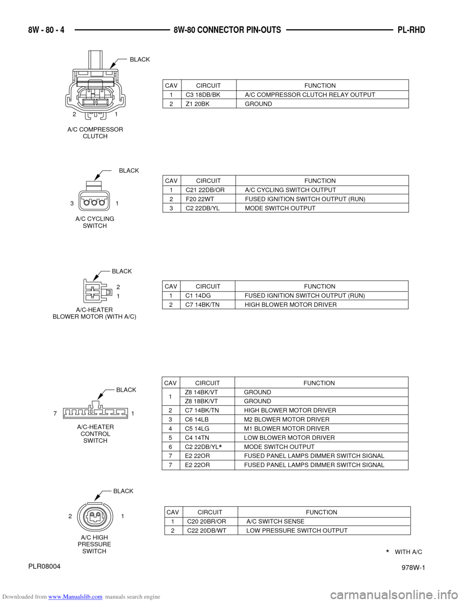
PL-RHD 8W - 80 - 4 8W-80 CONNECTOR PIN-OUTS
PLR08004
CAV CIRCUIT FUNCTION
1 C3 18DB/BK A/C COMPRESSOR CLUTCH RELAY OUTPUT
2 Z1 20BK GROUND
CAV CIRCUIT FUNCTION
1 C21 22DB/OR A/C CYCLING SWITCH OUTPUT
2 F20 22WT FUSED IGNITION SWITCH OUTPUT (RUN)
3 C2 22DB/YL MODE SWITCH OUTPUT
BLACK
A/C CYCLING
SWITCH
31
BLACK
71
CAV CIRCUIT FUNCTION
1Z8 14BK/VT GROUND
Z8 18BK/VT GROUND
2 C7 14BK/TN HIGH BLOWER MOTOR DRIVER
3 C6 14LB M2 BLOWER MOTOR DRIVER
4 C5 14LG M1 BLOWER MOTOR DRIVER
5 C4 14TN LOW BLOWER MOTOR DRIVER
6 C2 22DB/YL*MODE SWITCH OUTPUT
7 E2 22OR FUSED PANEL LAMPS DIMMER SWITCH SIGNAL
7 E2 22OR FUSED PANEL LAMPS DIMMER SWITCH SIGNAL
*WITH A/C A/C-HEATER
CONTROL
SWITCH
CAV CIRCUIT FUNCTION
1 C20 20BR/OR A/C SWITCH SENSE
2 C22 20DB/WT LOW PRESSURE SWITCH OUTPUT BLACK21
A/C HIGH
PRESSURE
SWITCH
1
A/C COMPRESSOR
CLUTCH
BLACK
2
2
1
A/C-HEATER
BLOWER MOTOR (WITH A/C)
BLACK
CAV CIRCUIT FUNCTION
1 C1 14DG FUSED IGNITION SWITCH OUTPUT (RUN)
2 C7 14BK/TN HIGH BLOWER MOTOR DRIVER
Page 193 of 256

Downloaded from www.Manualslib.com manuals search engine 978W-1
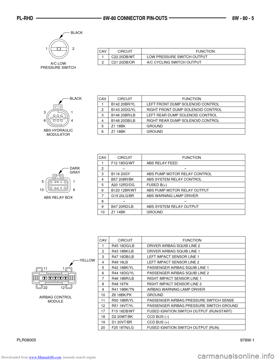
8W - 80 - 5 PL-RHD 8W-80 CONNECTOR PIN-OUTS
PLR08005
CAV CIRCUIT FUNCTION
1 C22 20DB/WT LOW PRESSURE SWITCH OUTPUT
2 C21 20DB/OR A/C CYCLING SWITCH OUTPUT
A/C LOW
PRESSURE SWITCH
BLACK
12
CAV CIRCUIT FUNCTION
1 B142 20BR/YL LEFT FRONT DUMP SOLENOID CONTROL
2 B143 20DG/YL RIGHT FRONT DUMP SOLENOID CONTROL
3 B146 20BR/LB LEFT REAR DUMP SOLENOID CONTROL
4 B148 20DB/LB RIGHT REAR DUMP SOLENOID CONTROL
5 Z1 18BK GROUND
6 Z1 18BK GROUND
BLACK
CAV CIRCUIT FUNCTION
1 F12 18DG/WT ABS RELAY FEED
2 Ð Ð
3 B116 20GY ABS PUMP MOTOR RELAY CONTROL
4 B57 20BR/BK ABS SYSTEM RELAY CONTROL
5 A20 12RD/DG FUSED B(+)
6 B120 12BR/WT ABS PUMP MOTOR RELAY OUTPUT
7 G19 20LG/BR ABS WARNING LAMP DRIVER
8 Ð Ð
9 B47 20RD/LB ABS SYSTEM RELAY OUTPUT
10 Z1 14BK GROUND
DARK
GRAY
ABS HYDRAULIC
MODULATOR 31
64
ABS RELAY BOX 51
10 6
CAV CIRCUIT FUNCTION
1 R45 18DG/LB DRIVER AIRBAG SQUIB LINE 2
2 R43 18BK/LB DRIVER AIRBAG SQUIB LINE 1
3 R47 18DB/LB LEFT IMPACT SENSOR LINE 1
4 R49 18LB LEFT IMPACT SENSOR LINE 2
5 R42 18BK/YL PASSENGER AIRBAG SQUIB LINE 1
6 R44 18DG/YL PASSENGER AIRBAG SQUIB LINE 2
7 R46 18BR/LB RIGHT IMPACT SENSOR LINE 1
8 R48 18TN RIGHT IMPACT SENSOR LINE 2
9 R41 18BK/TN AIRBAG WARNING LAMP DRIVER
10 Z6 18BK/PK GROUND
11 R50 18BR/YL PASSENGER AIRBAG PRESSURE SWTICH SENSE
12 R51 18VT/YL PASSENGER AIRBAG PRESSURE SWITCH GROUND
17 F15 18DB/WT FUSED IGNITION SWITCH OUTPUT (RUN/START)
18 D2 20WT/BK CCD BUS (Ð)
19 D1 20VT/BR CCD BUS (+)
20 F25 18TN/LG FUSED IGNITION SWITCH OUTPUT (RUN)
11 1
22 12
AIRBAG CONTROL
MODULEYELLOW
Page 200 of 256

Downloaded from www.Manualslib.com manuals search engine 978W-1
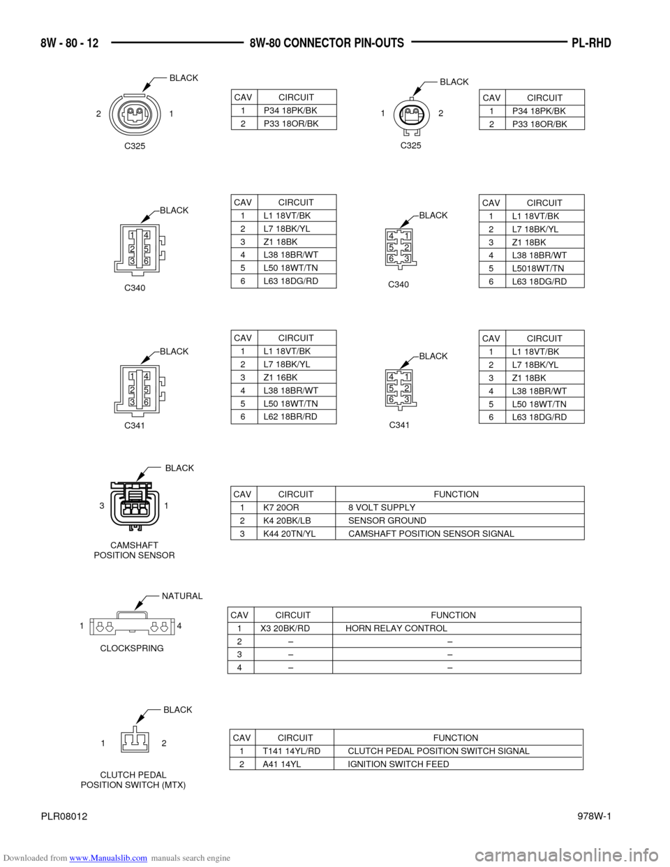
PL-RHD 8W - 80 - 12 8W-80 CONNECTOR PIN-OUTS
PLR08012
CAV CIRCUIT FUNCTION
1 K7 20OR 8 VOLT SUPPLY
2 K4 20BK/LB SENSOR GROUND
3 K44 20TN/YL CAMSHAFT POSITION SENSOR SIGNAL
CAV CIRCUIT FUNCTION
1 X3 20BK/RD HORN RELAY CONTROL
2Ð Ð
3Ð Ð
4Ð Ð
NATURAL
1 4
CLOCKSPRING
CAV CIRCUIT FUNCTION
1 T141 14YL/RD CLUTCH PEDAL POSITION SWITCH SIGNAL
2 A41 14YL IGNITION SWITCH FEED
CLUTCH PEDAL
POSITION SWITCH (MTX)BLACK
1 2
BLACKBLACK
CAV CIRCUIT
1 P34 18PK/BK
2 P33 18OR/BK
CAV CIRCUIT
1 P34 18PK/BK
2 P33 18OR/BK 122 1
C325C325
CAMSHAFT
POSITION SENSOR
31
BLACK
CAV CIRCUIT
1 L1 18VT/BK
2 L7 18BK/YL
3 Z1 18BK
4 L38 18BR/WT
5 L50 18WT/TN
6 L63 18DG/RD
CAV CIRCUIT
1 L1 18VT/BK
2 L7 18BK/YL
3 Z1 18BK
4 L38 18BR/WT
5 L5018WT/TN
6 L63 18DG/RD
C340C340
CAV CIRCUIT
1 L1 18VT/BK
2 L7 18BK/YL
3 Z1 16BK
4 L38 18BR/WT
5 L50 18WT/TN
6 L62 18BR/RD
CAV CIRCUIT
1 L1 18VT/BK
2 L7 18BK/YL
3 Z1 18BK
4 L38 18BR/WT
5 L50 18WT/TN
6 L63 18DG/RD
C341C341
14
25
36
BLACK
41
52
63BLACK
14
25
36
BLACK
41
52
63BLACK
Page 201 of 256

Downloaded from www.Manualslib.com manuals search engine 978W-1
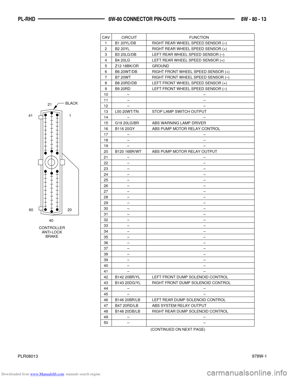
8W - 80 - 13PL-RHD 8W-80 CONNECTOR PIN-OUTS
PLR08013
CAV CIRCUIT FUNCTION
1 B1 20YL/DB RIGHT REAR WHEEL SPEED SENSOR (Ð)
2 B2 20YL RIGHT REAR WHEEL SPEED SENSOR (+)
3 B3 20LG/DB LEFT REAR WHEEL SPEED SENSOR (Ð)
4 B4 20LG LEFT REAR WHEEL SPEED SENSOR (+)
5 Z12 18BK/OR GROUND
6 B6 20WT/DB RIGHT FRONT WHEEL SPEED SENSOR (+)
7 B7 20WT RIGHT FRONT WHEEL SPEED SENSOR (Ð)
8 B8 20RD/DB LEFT FRONT WHEEL SPEED SENSOR (+)
9 B9 20RD LEFT FRONT WHEEL SPEED SENSOR (Ð)
10 Ð Ð
11 Ð Ð
12 Ð Ð
13 L50 20WT/TN STOP LAMP SWITCH OUTPUT
14 Ð Ð
15 G19 20LG/BR ABS WARNING LAMP DRIVER
16 B116 20GY ABS PUMP MOTOR RELAY CONTROL
17 Ð Ð
18 Ð Ð
19 Ð Ð
20 B120 16BR/WT ABS PUMP MOTOR RELAY OUTPUT
21 Ð Ð
22 Ð Ð
23 Ð Ð
24 Ð Ð
25 Ð Ð
26 Ð Ð
27 Ð Ð
28 Ð Ð
29 Ð Ð
30 Ð Ð
31 Ð Ð
32 Ð Ð
33 Ð Ð
34 Ð Ð
35 Ð Ð
36 Ð Ð
37 Ð Ð
38 Ð Ð
39 Ð Ð
40 Ð Ð
41 Ð Ð
42 B142 20BR/YL LEFT FRONT DUMP SOLENOID CONTROL
43 B143 20DG/YL RIGHT FRONT DUMP SOLENOID CONTROL
44 Ð Ð
45 Ð Ð
46 B146 20BR/LB LEFT REAR DUMP SOLENOID CONTROL
47 B47 20RD/LB ABS SYSTEM RELAY OUTPUT
48 B148 20DB/LB RIGHT REAR DUMP SOLENOID CONTROL
49 Ð Ð
50 Ð Ð
(CONTINUED ON NEXT PAGE)
BLACK
60 20 41 121
CONTROLLER
ANTI-LOCK
BRAKE40