fuel system DODGE NEON 1999 Service Repair Manual
[x] Cancel search | Manufacturer: DODGE, Model Year: 1999, Model line: NEON, Model: DODGE NEON 1999Pages: 1200, PDF Size: 35.29 MB
Page 893 of 1200
(9) Rotate throttle lever forward to the wide open
position and slide kickdown cable connector onto nail
head.
(10) Install throttle cable cover. Tighten bolt to 5.6
N´m (50 ins. lbs.).
THROTTLE POSITION SENSOR (TPS)
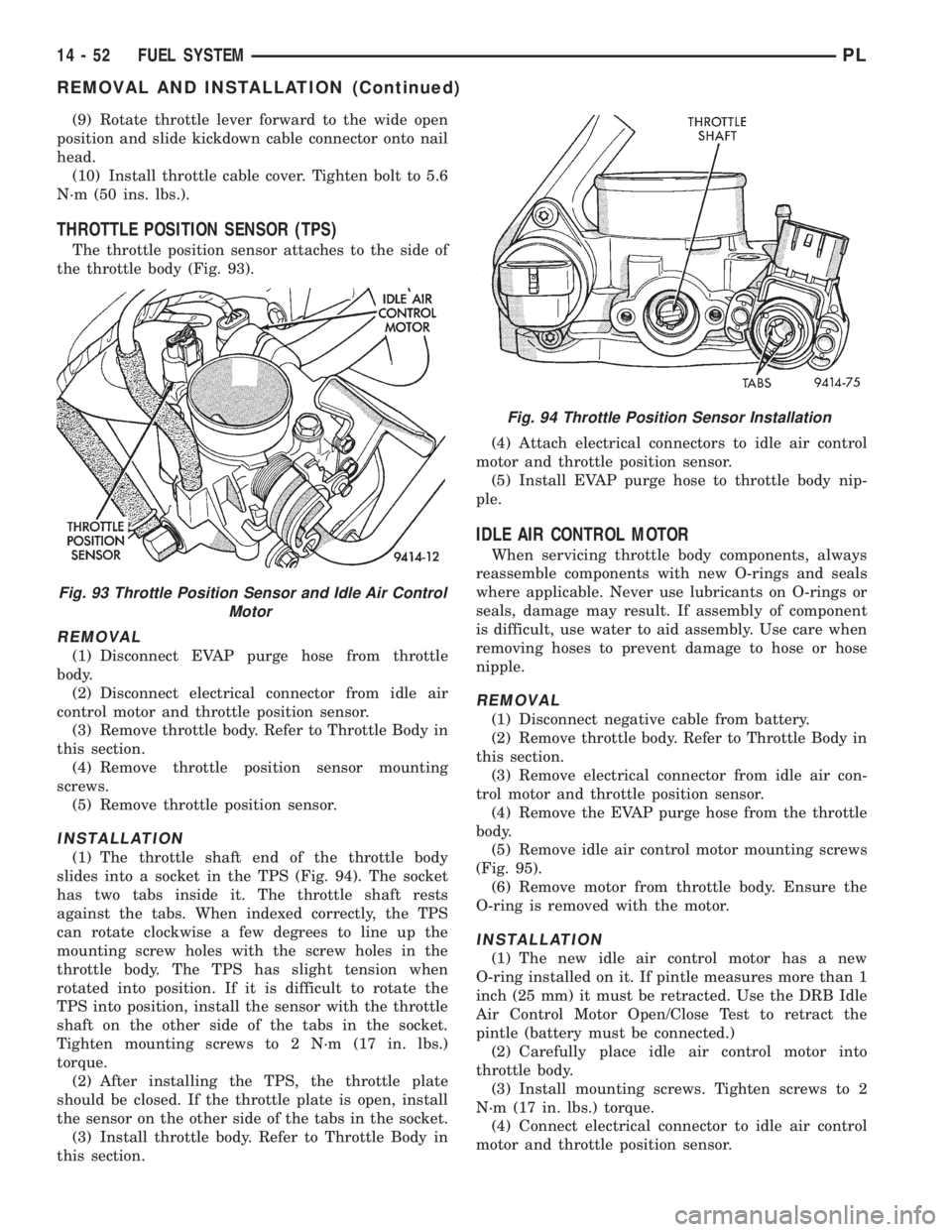
The throttle position sensor attaches to the side of
the throttle body (Fig. 93).
REMOVAL
(1) Disconnect EVAP purge hose from throttle
body.
(2) Disconnect electrical connector from idle air
control motor and throttle position sensor.
(3) Remove throttle body. Refer to Throttle Body in
this section.
(4) Remove throttle position sensor mounting
screws.
(5) Remove throttle position sensor.
INSTALLATION
(1) The throttle shaft end of the throttle body
slides into a socket in the TPS (Fig. 94). The socket
has two tabs inside it. The throttle shaft rests
against the tabs. When indexed correctly, the TPS
can rotate clockwise a few degrees to line up the
mounting screw holes with the screw holes in the
throttle body. The TPS has slight tension when
rotated into position. If it is difficult to rotate the
TPS into position, install the sensor with the throttle
shaft on the other side of the tabs in the socket.
Tighten mounting screws to 2 N´m (17 in. lbs.)
torque.
(2) After installing the TPS, the throttle plate
should be closed. If the throttle plate is open, install
the sensor on the other side of the tabs in the socket.
(3) Install throttle body. Refer to Throttle Body in
this section.(4) Attach electrical connectors to idle air control
motor and throttle position sensor.
(5) Install EVAP purge hose to throttle body nip-
ple.
IDLE AIR CONTROL MOTOR
When servicing throttle body components, always
reassemble components with new O-rings and seals
where applicable. Never use lubricants on O-rings or
seals, damage may result. If assembly of component
is difficult, use water to aid assembly. Use care when
removing hoses to prevent damage to hose or hose
nipple.
REMOVAL
(1) Disconnect negative cable from battery.
(2) Remove throttle body. Refer to Throttle Body in
this section.
(3) Remove electrical connector from idle air con-
trol motor and throttle position sensor.
(4) Remove the EVAP purge hose from the throttle
body.
(5) Remove idle air control motor mounting screws
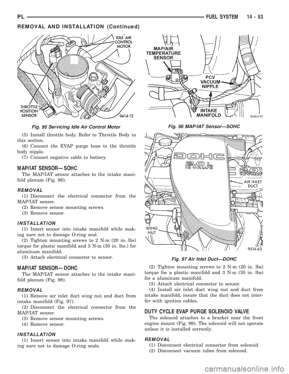
(Fig. 95).
(6) Remove motor from throttle body. Ensure the
O-ring is removed with the motor.
INSTALLATION
(1) The new idle air control motor has a new
O-ring installed on it. If pintle measures more than 1
inch (25 mm) it must be retracted. Use the DRB Idle
Air Control Motor Open/Close Test to retract the
pintle (battery must be connected.)
(2) Carefully place idle air control motor into
throttle body.
(3) Install mounting screws. Tighten screws to 2
N´m (17 in. lbs.) torque.
(4) Connect electrical connector to idle air control
motor and throttle position sensor.
Fig. 93 Throttle Position Sensor and Idle Air Control
Motor
Fig. 94 Throttle Position Sensor Installation
14 - 52 FUEL SYSTEMPL
REMOVAL AND INSTALLATION (Continued)
Page 894 of 1200
(5) Install throttle body. Refer to Throttle Body in
this section.
(6) Connect the EVAP purge hose to the throttle
body nipple.
(7) Connect negative cable to battery.
MAP/IAT SENSORÐSOHC
The MAP/IAT sensor attaches to the intake mani-
fold plenum (Fig. 96).
REMOVAL
(1) Disconnect the electrical connector from the
MAP/IAT sensor.
(2) Remove sensor mounting screws.
(3) Remove sensor.
INSTALLATION
(1) Insert sensor into intake manifold while mak-
ing sure not to damage O-ring seal.
(2) Tighten mounting screws to 2 N´m (20 in. lbs)
torque for plastic manifold and 3 N´m (30 in. lbs.) for
aluminum manifold.
(3) Attach electrical connector to sensor.
MAP/IAT SENSORÐDOHC
The MAP/IAT sensor attaches to the intake mani-
fold plenum (Fig. 98).
REMOVAL
(1) Remove air inlet duct wing nut and duct from
intake manifold (Fig. 97).
(2) Disconnect the electrical connector from the
MAP/IAT sensor.
(3) Remove sensor mounting screws.
(4) Remove sensor.
INSTALLATION
(1) Insert sensor into intake manifold while mak-
ing sure not to damage O-ring seals.(2) Tighten mounting screws to 2 N´m (20 in. lbs)
torque foe a plastic manifold and 3 N´m (30 in. lbs)
for a aluminum manifold.
(3) Attach electrical connector to sensor.
(4) Install air inlet duct wing nut and duct from
intake manifold, insure that the duct does not inter-
fer with ignition cables.
DUTY CYCLE EVAP PURGE SOLENOID VALVE
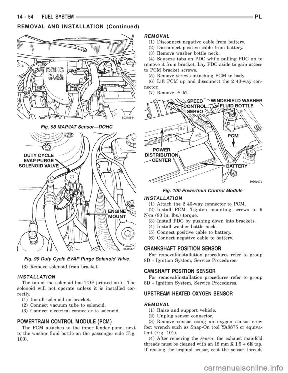
The solenoid attaches to a bracket near the front
engine mount (Fig. 99). The solenoid will not operate
unless it is installed correctly.
REMOVAL
(1) Disconnect electrical connector from solenoid.
(2) Disconnect vacuum tubes from solenoid.
Fig. 95 Servicing Idle Air Control MotorFig. 96 MAP/IAT SensorÐSOHC
Fig. 97 Air Inlet DuctÐDOHC
PLFUEL SYSTEM 14 - 53
REMOVAL AND INSTALLATION (Continued)
Page 895 of 1200
(3) Remove solenoid from bracket.
INSTALLATION
The top of the solenoid has TOP printed on it. The
solenoid will not operate unless it is installed cor-
rectly.
(1) Install solenoid on bracket.
(2) Connect vacuum tube to solenoid.
(3) Connect electrical connector to solenoid.
POWERTRAIN CONTROL MODULE (PCM)
The PCM attaches to the inner fender panel next
to the washer fluid bottle on the passenger side (Fig.
100).
REMOVAL
(1) Disconnect negative cable from battery.
(2) Disconnect positive cable from battery.
(3) Remove washer bottle neck.
(4) Squeeze tabs on PDC while pulling PDC up to
remove it from bracket. Lay PDC aside to gain access
to PCM bracket screws.
(5) Remove screws attaching PCM to body.
(6) Lift PCM up and disconnect the 2 40-way con-
nector.
(7) Remove PCM.
INSTALLATION
(1) Attach the 2 40-way connector to PCM.
(2) Install PCM. Tighten mounting screws to 9
N´m (80 in. lbs.) torque.
(3) Install PDC by pushing down into brackets.
(4) Install washer bottle neck.
(5) Connect positive cable to battery.
(6) Connect negative cable to battery.
CRANKSHAFT POSITION SENSOR
For removal/installation procedures refer to group
8D - Ignition System, Service Procedures.
CAMSHAFT POSITION SENSOR
For removal/installation procedures refer to group
8D - Ignition System, Service Procedures.
UPSTREAM HEATED OXYGEN SENSOR
REMOVAL
(1) Raise and support vehicle.
(2) Unplug sensor connector.
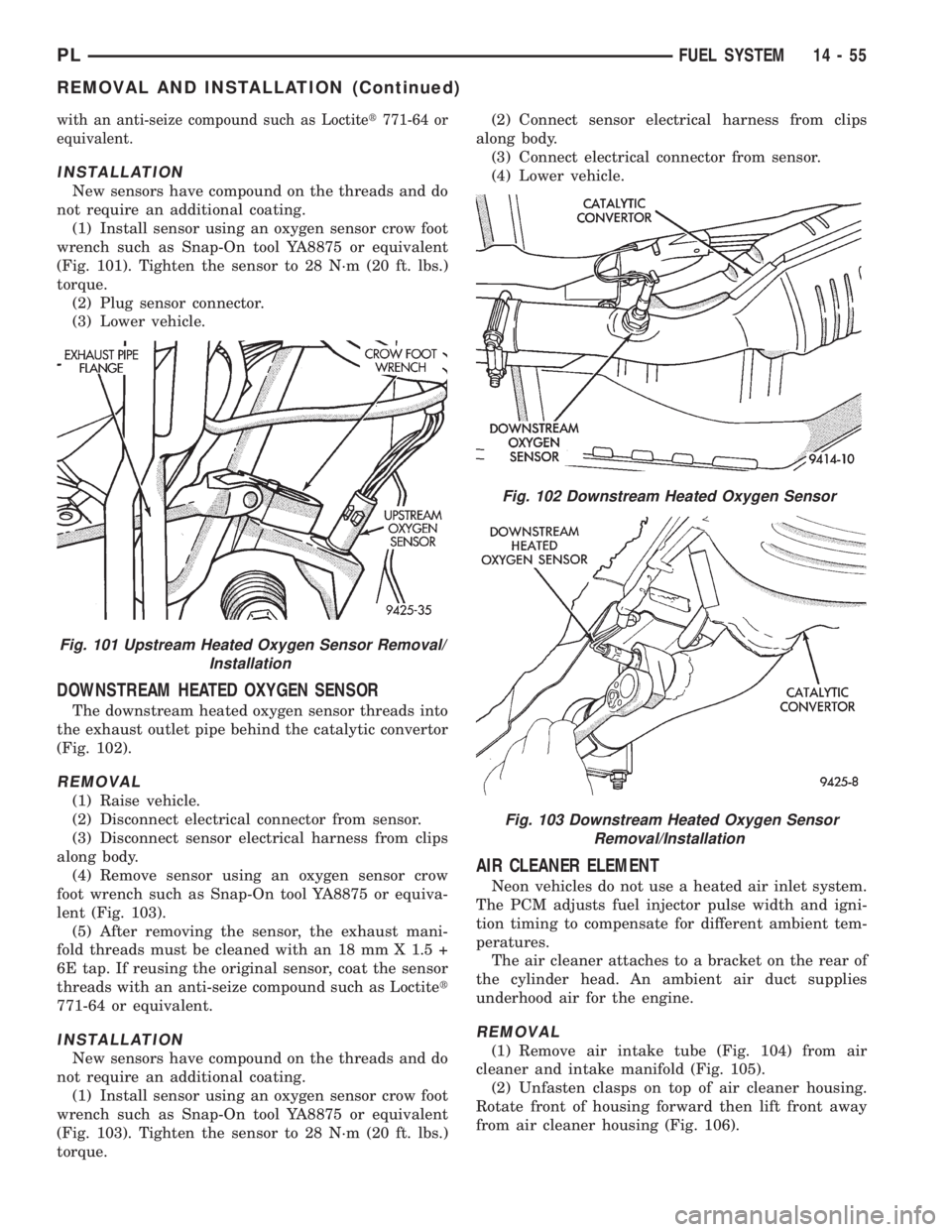
(3) Remove sensor using an oxygen sensor crow
foot wrench such as Snap-On tool YA8875 or equiva-
lent (Fig. 101).
(4) A
fter removing the sensor, the exhaust manifold
threads must be cleaned with an 18 mm X 1.5 + 6E tap.
If reusing the original sensor, coat the sensor threads
Fig. 98 MAP/IAT SensorÐDOHC
Fig. 99 Duty Cycle EVAP Purge Solenoid Valve
Fig. 100 Powertrain Control Module
14 - 54 FUEL SYSTEMPL
REMOVAL AND INSTALLATION (Continued)
Page 896 of 1200
with an anti-seize compound such as Loctitet771-64 or
equivalent.
INSTALLATION
New sensors have compound on the threads and do
not require an additional coating.
(1) Install sensor using an oxygen sensor crow foot
wrench such as Snap-On tool YA8875 or equivalent
(Fig. 101). Tighten the sensor to 28 N´m (20 ft. lbs.)
torque.
(2) Plug sensor connector.
(3) Lower vehicle.
DOWNSTREAM HEATED OXYGEN SENSOR
The downstream heated oxygen sensor threads into
the exhaust outlet pipe behind the catalytic convertor
(Fig. 102).
REMOVAL
(1) Raise vehicle.
(2) Disconnect electrical connector from sensor.
(3) Disconnect sensor electrical harness from clips
along body.
(4) Remove sensor using an oxygen sensor crow
foot wrench such as Snap-On tool YA8875 or equiva-
lent (Fig. 103).
(5) After removing the sensor, the exhaust mani-
fold threads must be cleaned with an 18 mm X 1.5 +
6E tap. If reusing the original sensor, coat the sensor
threads with an anti-seize compound such as Loctitet
771-64 or equivalent.
INSTALLATION
New sensors have compound on the threads and do
not require an additional coating.
(1) Install sensor using an oxygen sensor crow foot
wrench such as Snap-On tool YA8875 or equivalent
(Fig. 103). Tighten the sensor to 28 N´m (20 ft. lbs.)
torque.(2) Connect sensor electrical harness from clips
along body.
(3) Connect electrical connector from sensor.
(4) Lower vehicle.
AIR CLEANER ELEMENT
Neon vehicles do not use a heated air inlet system.
The PCM adjusts fuel injector pulse width and igni-
tion timing to compensate for different ambient tem-
peratures.
The air cleaner attaches to a bracket on the rear of
the cylinder head. An ambient air duct supplies
underhood air for the engine.
REMOVAL
(1) Remove air intake tube (Fig. 104) from air
cleaner and intake manifold (Fig. 105).
(2) Unfasten clasps on top of air cleaner housing.
Rotate front of housing forward then lift front away
from air cleaner housing (Fig. 106).
Fig. 101 Upstream Heated Oxygen Sensor Removal/
Installation
Fig. 102 Downstream Heated Oxygen Sensor
Fig. 103 Downstream Heated Oxygen Sensor
Removal/Installation
PLFUEL SYSTEM 14 - 55
REMOVAL AND INSTALLATION (Continued)
Page 897 of 1200
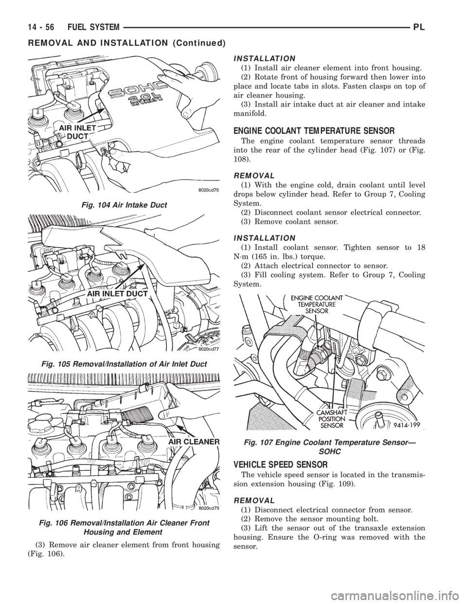
(3) Remove air cleaner element from front housing
(Fig. 106).
INSTALLATION
(1) Install air cleaner element into front housing.
(2) Rotate front of housing forward then lower into
place and locate tabs in slots. Fasten clasps on top of
air cleaner housing.
(3) Install air intake duct at air cleaner and intake
manifold.
ENGINE COOLANT TEMPERATURE SENSOR
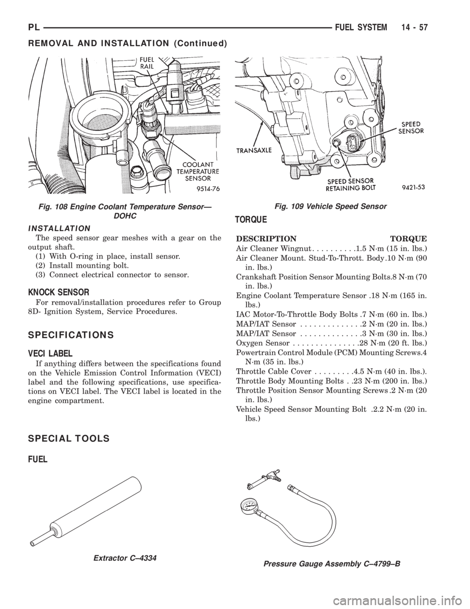
The engine coolant temperature sensor threads
into the rear of the cylinder head (Fig. 107) or (Fig.
108).
REMOVAL
(1) With the engine cold, drain coolant until level
drops below cylinder head. Refer to Group 7, Cooling
System.
(2) Disconnect coolant sensor electrical connector.
(3) Remove coolant sensor.
INSTALLATION
(1) Install coolant sensor. Tighten sensor to 18
N´m (165 in. lbs.) torque.
(2) Attach electrical connector to sensor.
(3) Fill cooling system. Refer to Group 7, Cooling
System.
VEHICLE SPEED SENSOR
The vehicle speed sensor is located in the transmis-
sion extension housing (Fig. 109).
REMOVAL
(1) Disconnect electrical connector from sensor.
(2) Remove the sensor mounting bolt.
(3) Lift the sensor out of the transaxle extension
housing. Ensure the O-ring was removed with the
sensor.
Fig. 104 Air Intake Duct
Fig. 105 Removal/Installation of Air Inlet Duct
Fig. 106 Removal/Installation Air Cleaner Front
Housing and Element
Fig. 107 Engine Coolant Temperature SensorÐ
SOHC
14 - 56 FUEL SYSTEMPL
REMOVAL AND INSTALLATION (Continued)
Page 898 of 1200
INSTALLATION
The speed sensor gear meshes with a gear on the
output shaft.
(1) With O-ring in place, install sensor.
(2) Install mounting bolt.
(3) Connect electrical connector to sensor.
KNOCK SENSOR
For removal/installation procedures refer to Group
8D- Ignition System, Service Procedures.
SPECIFICATIONS
VECI LABEL
If anything differs between the specifications found
on the Vehicle Emission Control Information (VECI)
label and the following specifications, use specifica-
tions on VECI label. The VECI label is located in the
engine compartment.
TORQUE
DESCRIPTION TORQUE
Air Cleaner Wingnut..........1.5 N´m (15 in. lbs.)
Air Cleaner Mount. Stud-To-Thrott. Body .10 N´m (90
in. lbs.)
Crankshaft Position Sensor Mounting Bolts.8 N´m (70
in. lbs.)
Engine Coolant Temperature Sensor .18 N´m (165 in.
lbs.)
IAC Motor-To-Throttle Body Bolts .7 N´m (60 in. lbs.)
MAP/IAT Sensor..............2N´m(20in.lbs.)
MAP/IAT Sensor..............3N´m(30in.lbs.)
Oxygen Sensor...............28N´m(20ft.lbs.)
Powertrain Control Module (PCM) Mounting Screws.4
N´m (35 in. lbs.)
Throttle Cable Cover.........4.5 N´m (40 in. lbs.).
Throttle Body Mounting Bolts . .23 N´m (200 in. lbs.)
Throttle Position Sensor Mounting Screws .2 N´m (20
in. lbs.)
Vehicle Speed Sensor Mounting Bolt .2.2 N´m (20 in.
lbs.)
SPECIAL TOOLS
FUEL
Fig. 108 Engine Coolant Temperature SensorÐ
DOHCFig. 109 Vehicle Speed Sensor
Extractor C±4334Pressure Gauge Assembly C±4799±B
PLFUEL SYSTEM 14 - 57
REMOVAL AND INSTALLATION (Continued)
Page 899 of 1200
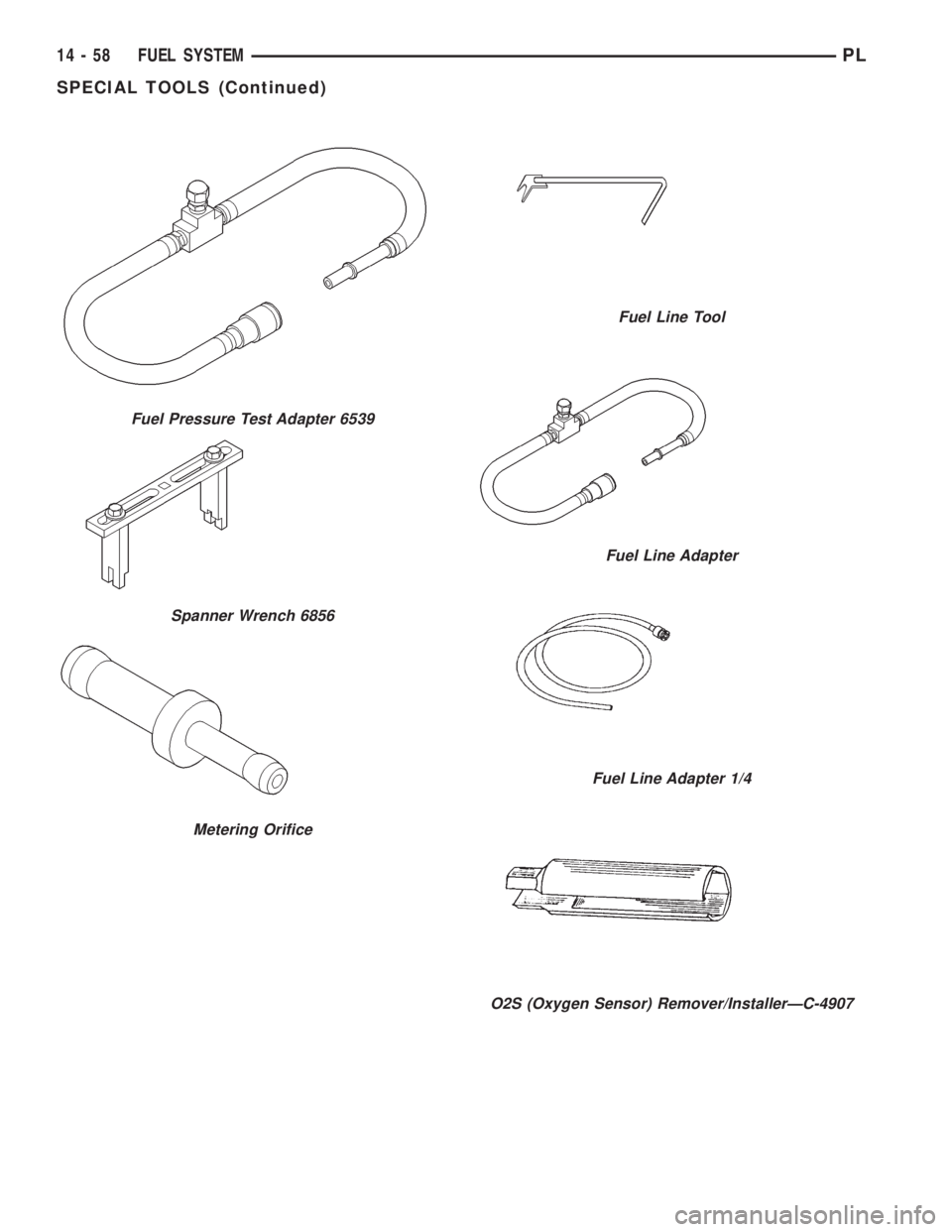
Fuel Pressure Test Adapter 6539
Spanner Wrench 6856
Metering Orifice
Fuel Line Tool
Fuel Line Adapter
Fuel Line Adapter 1/4
O2S (Oxygen Sensor) Remover/InstallerÐC-4907
14 - 58 FUEL SYSTEMPL
SPECIAL TOOLS (Continued)
Page 900 of 1200
FUEL SYSTEMÐ1.8L ENGINE
CONTENTS
page
GENERAL INFORMATION
FUEL SYSTEMÐ1.8L SOHC ENGINE....... 1
GENERAL INFORMATION
FUEL SYSTEMÐ1.8L SOHC ENGINE
The fuel delivery system used on the 1.8L SOHC
engine operates the same as the fuel system used on
the 2.0L SOHC engine. It also contains the samecomponents as the 2.0L engine, and the service pro-
cedures are the same. Refer to group 14 for the 2.0L
engine in this manual for a complete description of
the fuel system and its service procedures.
PLFUEL SYSTEMÐ1.8L ENGINE 14 - 1
Page 1164 of 1200
EMISSION CONTROL SYSTEMS
CONTENTS
page page
EVAPORATIVE EMISSION CONTROLS........ 11
EXHAUST GAS RECIRCULATION (EGR)
SYSTEM.............................. 18ON-BOARD DIAGNOSTICS.................. 1
ON-BOARD DIAGNOSTICS
INDEX
page page
GENERAL INFORMATION
SYSTEM DESCRIPTION................... 1
DESCRIPTION AND OPERATION
CIRCUIT ACTUATION TEST MODE........... 2
COMPONENT MONITORS.................. 9
DIAGNOSTIC TROUBLE CODES............. 2
HIGH AND LOW LIMITS................... 10LOAD VALUE........................... 10
MALFUNCTION INDICATOR LAMP (MIL)....... 1
MONITORED SYSTEMS.................... 6
NON-MONITORED CIRCUITS............... 9
STATE DISPLAY TEST MODE............... 2
TRIP DEFINITION........................ 9
GENERAL INFORMATION
SYSTEM DESCRIPTION
The Powertrain Control Module (PCM) monitors
many different circuits in the fuel injection, ignition,
emission and engine systems. If the PCM senses a
problem with a monitored circuit often enough to
indicate an actual problem, it stores a Diagnostic
Trouble Code (DTC) in the PCM's memory. If the
code applies to a non-emissions related component or
system, and the problem is repaired or ceases to
exist, the PCM cancels the code after 40 warmup
cycles. Diagnostic trouble codes that affect vehicle
emissions illuminate the Malfunction Indicator Lamp
(MIL). Refer to Malfunction Indicator Lamp in this
section.
Certain criteria must be met before the PCM
stores a DTC in memory. The criteria may be a spe-
cific range of engine RPM, engine temperature,
and/or input voltage to the PCM.
The PCM might not store a DTC for a monitored
circuit even though a malfunction has occurred. This
may happen because one of the DTC criteria for the
circuit has not been met.For example, assume the
diagnostic trouble code criteria requires the PCM to
monitor the circuit only when the engine operates
between 750 and 2000 RPM. Suppose the sensor'soutput circuit shorts to ground when engine operates
above 2400 RPM (resulting in 0 volt input to the
PCM). Because the condition happens at an engine
speed above the maximum threshold (2000 rpm), the
PCM will not store a DTC.
There are several operating conditions for which
the PCM monitors and sets DTC's. Refer to Moni-
tored Systems, Components, and Non-Monitored Cir-
cuits in this section.
NOTE: Various diagnostic procedures may actually
cause a diagnostic monitor to set a DTC. For
instance, pulling a spark plug wire to perform a
spark test may set the misfire code. When a repair
is completed and verified, use the DRB scan tool to
erase all DTC's and extinguish the MIL.
Technicians can display stored DTC's by using the
DRB scan tool. Refer to Diagnostic Trouble Codes in
this section. For DTC information, refer to charts in
this section.
DESCRIPTION AND OPERATION
MALFUNCTION INDICATOR LAMP (MIL)
As a functional test, the Malfunction Indicator
Lamp (MIL) illuminates at key-on before engine
PLEMISSION CONTROL SYSTEMS 25 - 1
Page 1165 of 1200
cranking. Whenever the Powertrain Control Module
(PCM) sets a Diagnostic Trouble Code (DTC) that
affects vehicle emissions, it illuminates the MIL. If a
problem is detected, the PCM sends a message over
the CCD Bus to the instrument cluster to illuminate
the lamp. The PCM illuminates the MIL only for
DTC's that affect vehicle emissions. The MIL stays
on continuously when the PCM has entered a
Limp-In mode or identified a failed emission compo-
nent or system. The MIL remains on until the DTC
is erased. Refer to the Diagnostic Trouble Code
charts in this group for emission related codes.
Also, the MIL either flashes or illuminates contin-
uously when the PCM detects active engine misfire.
Refer to Misfire Monitoring in this section.
Additionally, the PCM may reset (turn off) the MIL
when one of the following occur:
²PCM does not detect the malfunction for 3 con-
secutive trips (except misfire and fuel system moni-
tors).
²PCM does not detect a malfunction while per-
forming three successive engine misfire or fuel sys-
tem tests. The PCM performs these tests while the
engine is operating within6375 RPM of and within
10 % of the load of the operating condition at which
the malfunction was first detected.
STATE DISPLAY TEST MODE
The switch inputs to the Powertrain Control Mod-
ule (PCM) have two recognized states; HIGH and
LOW. For this reason, the PCM cannot recognize the
difference between a selected switch position versus
an open circuit, a short circuit, or a defective switch.
If the State Display screen shows the change from
HIGH to LOW or LOW to HIGH, assume the entire
switch circuit to the PCM functions properly. From
the state display screen, access either State Display
Inputs and Outputs or State Display Sensors.
CIRCUIT ACTUATION TEST MODE
The Circuit Actuation Test Mode checks for proper
operation of output circuits or devices the Powertrain
Control Module (PCM) may not internally recognize.
The PCM attempts to activate these outputs and
allow an observer to verify proper operation. Most of
the tests provide an audible or visual indication of
device operation (click of relay contacts, fuel spray,
etc.). Except for intermittent conditions, if a device
functions properly during testing, assume the device,
its associated wiring, and driver circuit work cor-
rectly.
DIAGNOSTIC TROUBLE CODES
A Diagnostic Trouble Code (DTC) indicates the
PCM has recognized an abnormal condition in the
system.
²The preferred and most accurate method of
retrieving a DTC is by using the DRB scan tool. The
scan tool supplies detailed diagnostic information
which can be used to more accurately diagnose
causes for a DTC.
Remember that DTC's are the results of a sys-
tem or circuit failure, but do not directly iden-
tify the failed component or components.
NOTE: For a list of DTC's, refer to the charts in this
section.
BULB CHECK
Each time the ignition key is turned to the ON
position, the malfunction indicator (check engine)
lamp on the instrument panel should illuminate for
approximately 2 seconds then go out. This is done for
a bulb check.
OBTAINING DTC'S USING DRB SCAN TOOL
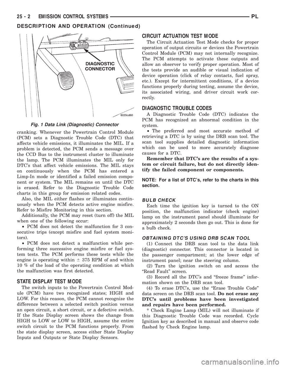
(1) Connect the DRB scan tool to the data link
(diagnostic) connector. This connector is located in
the passenger compartment; at the lower edge of
instrument panel; near the steering column.
(2) Turn the ignition switch on and access the
ªRead Faultº screen.
(3) Record all the DTC's and ªfreeze frameº infor-
mation shown on the DRB scan tool.
(4) To erase DTC's, use the ªErase Trouble Codeº
data screen on the DRB scan tool.Do not erase any
DTC's until problems have been investigated
and repairs have been performed.
* Check Engine Lamp (MIL) will not illuminate if
this Diagnostic Trouble Code was recorded. Cycle
Ignition key as described in manual and observe code
flashed by Check Engine lamp.
Fig. 1 Data Link (Diagnostic) Connector
25 - 2 EMISSION CONTROL SYSTEMSPL
DESCRIPTION AND OPERATION (Continued)