engine oil DODGE NEON 1999 Service Repair Manual
[x] Cancel search | Manufacturer: DODGE, Model Year: 1999, Model line: NEON, Model: DODGE NEON 1999Pages: 1200, PDF Size: 35.29 MB
Page 1152 of 1200
(4) Remove two resistor block retaining screws.
The screw threads attaching the resistor block are
not full length. It is necessary to gently pry out the
resistor block while turning the screws counterclock-
wise enabling the threads to engages.
(5) Remove resistor block from vehicle.
INSTALLATION
For installation, reverse the above procedures.
BLOWER MOTOR WHEEL
The blower motor wheel is only serviced with the
blower motor. The wheel and the motor are balanced
as an assembly. If the blower motor wheel requires
replacement, the blower motor must also be replaced.
Refer to blower motor for replacement procedure.
COMPRESSOR
CAUTION: Add only new lubricant when system
requires additional lubricant. Do not use old
reclaimed lubricant.
REMOVAL
The A/C compressor may be unbolted and reposi-
tioned without discharging the refrigerant system.
Discharging is not necessary if removing the com-
pressor clutch/coil assembly, engine, cylinder head, or
alternator.
WARNING: REFRIGERANT PRESSURES REMAIN
HIGH EVEN THOUGH THE ENGINE MAY BE
TURNED OFF. DO NOT TWIST OR KINK THE
REFRIGERANT LINES WHEN REMOVING A FULLY
CHARGED COMPRESSOR. SAFETY GLASSES
MUST BE WORN.
(1) Disconnect battery negative cable.
(2) Loosen and remove drive belts, refer to Group
7, Engine Cooling.
(3) Using a R-134a refrigerant recovery machine,
remove the refrigerant from A/C system. If the com-
pressor is being replaced.
(4) Disconnect compressor clutch wire lead.
(5) Remove refrigerant lines from compressor, if
necessary.
(6) If system is left open place plug/cap over open
lines.
(7) Remove compressor attaching bolt.
(8) Remove compressor. If refrigerant lines were
not removed, lift compressor/clutch assembly and tie
it to a suitable component.
INSTALLATION
For installation, reverse the above procedures.
COMPRESSOR CLUTCH/COIL ASSEMBLY
Compressor assembly must be removed from mount-
ing. Although, refrigerant discharge is not necessary.
REMOVAL
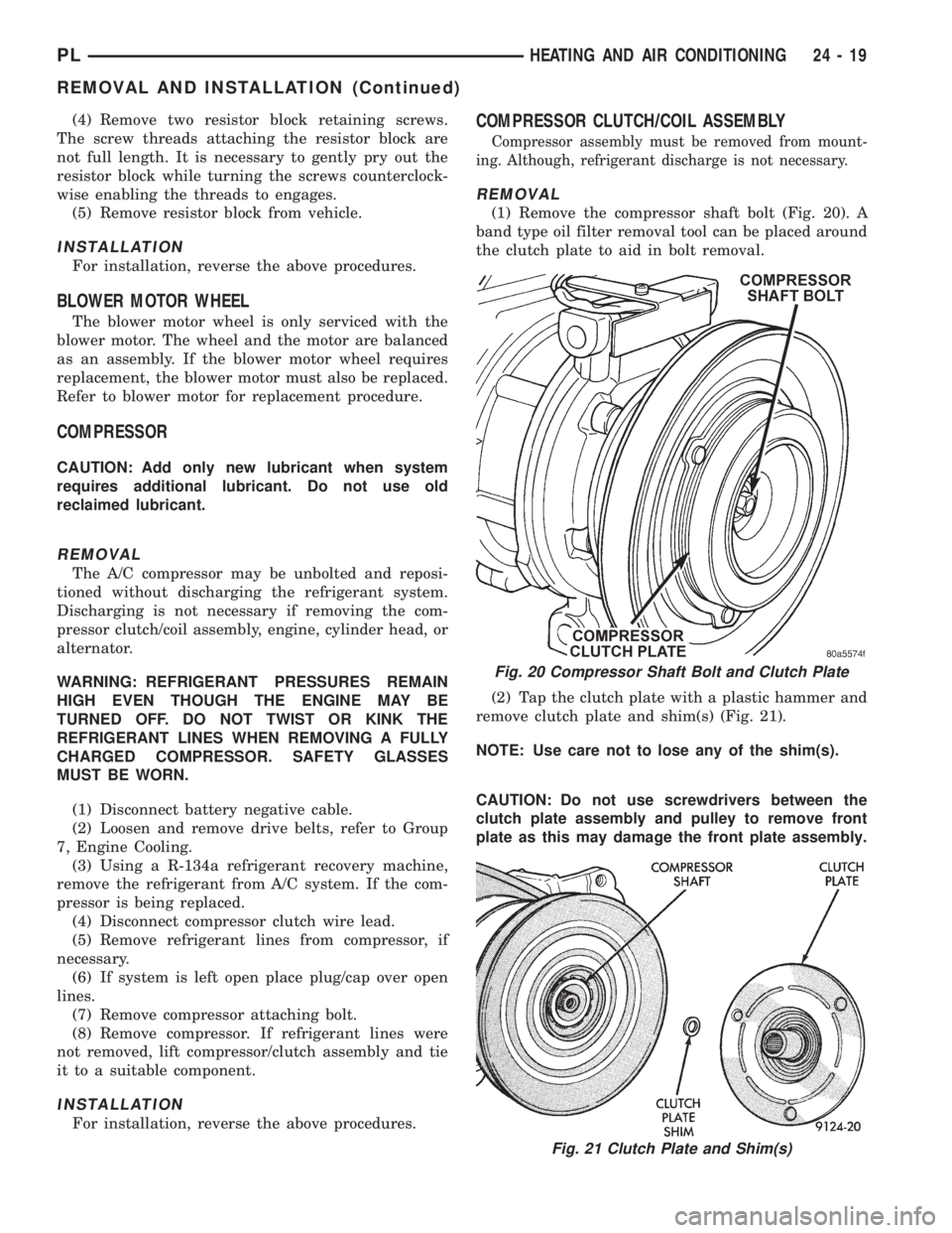
(1) Remove the compressor shaft bolt (Fig. 20). A
band type oil filter removal tool can be placed around
the clutch plate to aid in bolt removal.
(2) Tap the clutch plate with a plastic hammer and
remove clutch plate and shim(s) (Fig. 21).
NOTE: Use care not to lose any of the shim(s).
CAUTION: Do not use screwdrivers between the
clutch plate assembly and pulley to remove front
plate as this may damage the front plate assembly.
Fig. 20 Compressor Shaft Bolt and Clutch Plate
Fig. 21 Clutch Plate and Shim(s)
PLHEATING AND AIR CONDITIONING 24 - 19
REMOVAL AND INSTALLATION (Continued)
Page 1167 of 1200
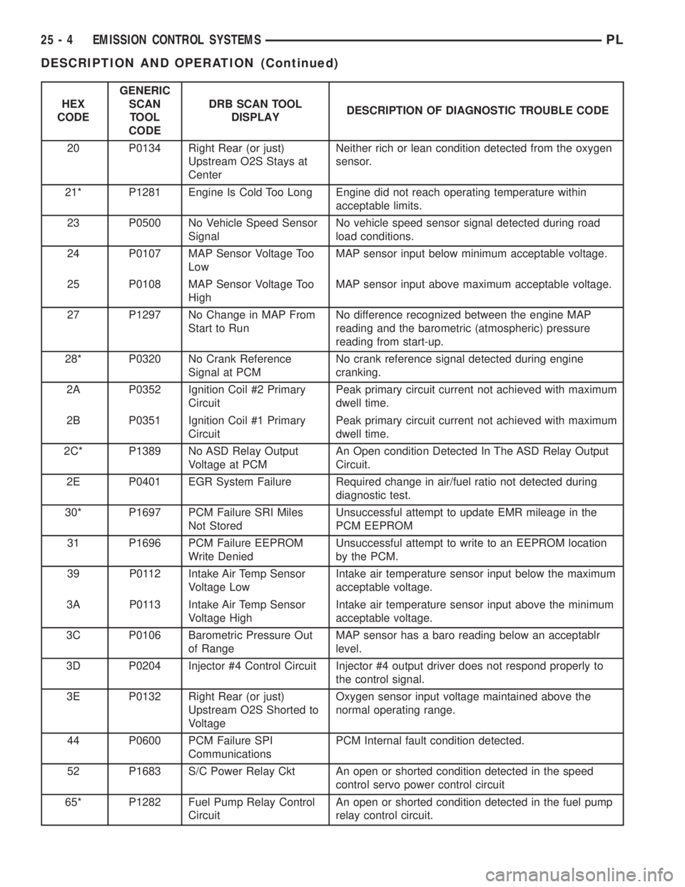
HEX
CODEGENERIC
SCAN
TOOL
CODEDRB SCAN TOOL
DISPLAYDESCRIPTION OF DIAGNOSTIC TROUBLE CODE
20 P0134 Right Rear (or just)
Upstream O2S Stays at
CenterNeither rich or lean condition detected from the oxygen
sensor.
21* P1281 Engine Is Cold Too Long Engine did not reach operating temperature within
acceptable limits.
23 P0500 No Vehicle Speed Sensor
SignalNo vehicle speed sensor signal detected during road
load conditions.
24 P0107 MAP Sensor Voltage Too
LowMAP sensor input below minimum acceptable voltage.
25 P0108 MAP Sensor Voltage Too
HighMAP sensor input above maximum acceptable voltage.
27 P1297 No Change in MAP From
Start to RunNo difference recognized between the engine MAP
reading and the barometric (atmospheric) pressure
reading from start-up.
28* P0320 No Crank Reference
Signal at PCMNo crank reference signal detected during engine
cranking.
2A P0352 Ignition Coil #2 Primary
CircuitPeak primary circuit current not achieved with maximum
dwell time.
2B P0351 Ignition Coil #1 Primary
CircuitPeak primary circuit current not achieved with maximum
dwell time.
2C* P1389 No ASD Relay Output
Voltage at PCMAn Open condition Detected In The ASD Relay Output
Circuit.
2E P0401 EGR System Failure Required change in air/fuel ratio not detected during
diagnostic test.
30* P1697 PCM Failure SRI Miles
Not StoredUnsuccessful attempt to update EMR mileage in the
PCM EEPROM
31 P1696 PCM Failure EEPROM
Write DeniedUnsuccessful attempt to write to an EEPROM location
by the PCM.
39 P0112 Intake Air Temp Sensor
Voltage LowIntake air temperature sensor input below the maximum
acceptable voltage.
3A P0113 Intake Air Temp Sensor
Voltage HighIntake air temperature sensor input above the minimum
acceptable voltage.
3C P0106 Barometric Pressure Out
of RangeMAP sensor has a baro reading below an acceptablr
level.
3D P0204 Injector #4 Control Circuit Injector #4 output driver does not respond properly to
the control signal.
3E P0132 Right Rear (or just)
Upstream O2S Shorted to
VoltageOxygen sensor input voltage maintained above the
normal operating range.
44 P0600 PCM Failure SPI
CommunicationsPCM Internal fault condition detected.
52 P1683 S/C Power Relay Ckt An open or shorted condition detected in the speed
control servo power control circuit
65* P1282 Fuel Pump Relay Control
CircuitAn open or shorted condition detected in the fuel pump
relay control circuit.
25 - 4 EMISSION CONTROL SYSTEMSPL
DESCRIPTION AND OPERATION (Continued)
Page 1173 of 1200
FUEL PRESSURE
The fuel pressure regulator controls fuel system
pressure. The PCM cannot detect a clogged fuel
pump inlet filter, clogged in-line fuel filter, or a
pinched fuel supply or return line. However, these
could result in a rich or lean condition causing the
PCM to store an oxygen sensor or fuel system diag-
nostic trouble code.
SECONDARY IGNITION CIRCUIT
The PCM cannot detect an inoperative ignition coil,
fouled or worn spark plugs, ignition cross firing, or
open spark plug cables.
CYLINDER COMPRESSION
The PCM cannot detect uneven, low, or high engine
cylinder compression.
EXHAUST SYSTEM
The PCM cannot detect a plugged, restricted or
leaking exhaust system. It may set a EGR or Fuel
system fault or O2S.
FUEL INJECTOR MECHANICAL
MALFUNCTIONS
The PCM cannot determine if a fuel injector is
clogged, the needle is sticking or if the wrong injector
is installed. However, these could result in a rich or
lean condition causing the PCM to store a diagnostic
trouble code for either misfire, an oxygen sensor, or
the fuel system.
EXCESSIVE OIL CONSUMPTION
Although the PCM monitors engine exhaust oxygen
content when the system is in closed loop, it cannot
determine excessive oil consumption.
THROTTLE BODY AIR FLOW
The PCM cannot detect a clogged or restricted air
cleaner inlet or filter element.
VACUUM ASSIST
The PCM cannot detect leaks or restrictions in the
vacuum circuits of vacuum assisted engine control
system devices. However, these could cause the PCM
to store a MAP sensor diagnostic trouble code and
cause a high idle condition.
PCM SYSTEM GROUND
The PCM cannot determine a poor system ground.
However, one or more diagnostic trouble codes may
be generated as a result of this condition. The mod-
ule should be mounted to the body at all times, also
during diagnostic.
PCM CONNECTOR ENGAGEMENT
The PCM may not be able to determine spread or
damaged connector pins. However, it might store
diagnostic trouble codes as a result of spread connec-
tor pins.
HIGH AND LOW LIMITS
The PCM compares input signal voltages from each
input device with established high and low limits for
the device. If the input voltage is not within limits
and other criteria are met, the PCM stores a diagnos-
tic trouble code in memory. Other diagnostic trouble
code criteria might include engine RPM limits or
input voltages from other sensors or switches that
must be present before verifying a diagnostic trouble
code condition.
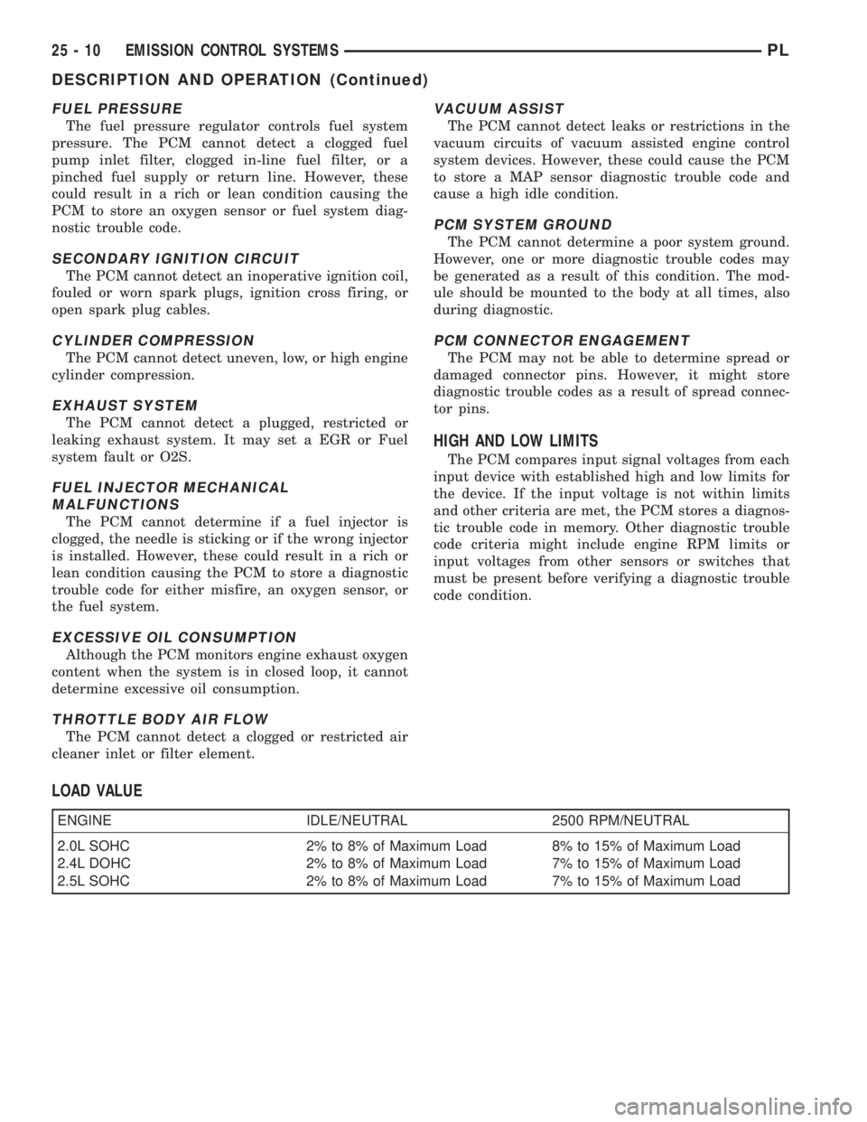
LOAD VALUE
ENGINE IDLE/NEUTRAL 2500 RPM/NEUTRAL
2.0L SOHC 2% to 8% of Maximum Load 8% to 15% of Maximum Load
2.4L DOHC 2% to 8% of Maximum Load 7% to 15% of Maximum Load
2.5L SOHC 2% to 8% of Maximum Load 7% to 15% of Maximum Load
25 - 10 EMISSION CONTROL SYSTEMSPL
DESCRIPTION AND OPERATION (Continued)