open gas tank DODGE NEON 1999 Service Repair Manual
[x] Cancel search | Manufacturer: DODGE, Model Year: 1999, Model line: NEON, Model: DODGE NEON 1999Pages: 1200, PDF Size: 35.29 MB
Page 198 of 1200
SELECTION AND ADDITIVES
The use of aluminum cylinder heads, intake mani-
folds DOHC, and water pumps requires special corro-
sion protection. MopartAntifreeze or the equivalent
is recommended for best engine cooling without cor-
rosion. When mixed only to a freeze point of -37ÉC
(-35ÉF) to -59ÉC (-50ÉF). If it looses color or becomes
contaminated, drain, flush, and replace with fresh
properly mixed solution.
COOLING SYSTEM PRESSURE CAP
The cooling system is equipped with a pressure cap
that releases built up pressure, maintaining a range
of 97-124 kPa (14-18 psi).
The cooling system will operate at higher than
atmospheric pressure. The higher pressure raises the
coolant boiling point thus, allowing increased radia-
tor cooling capacity.
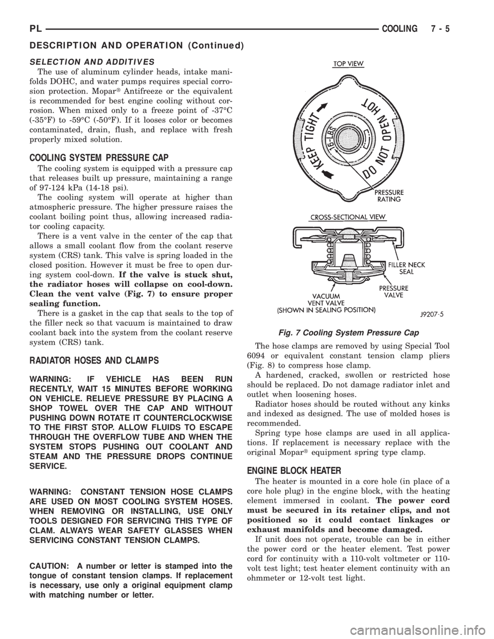
There is a vent valve in the center of the cap that
allows a small coolant flow from the coolant reserve
system (CRS) tank. This valve is spring loaded in the
closed position. However it must be free to open dur-
ing system cool-down.If the valve is stuck shut,
the radiator hoses will collapse on cool-down.
Clean the vent valve (Fig. 7) to ensure proper
sealing function.
There is a gasket in the cap that seals to the top of
the filler neck so that vacuum is maintained to draw
coolant back into the system from the coolant reserve
system (CRS) tank.
RADIATOR HOSES AND CLAMPS
WARNING: IF VEHICLE HAS BEEN RUN
RECENTLY, WAIT 15 MINUTES BEFORE WORKING
ON VEHICLE. RELIEVE PRESSURE BY PLACING A
SHOP TOWEL OVER THE CAP AND WITHOUT
PUSHING DOWN ROTATE IT COUNTERCLOCKWISE
TO THE FIRST STOP. ALLOW FLUIDS TO ESCAPE
THROUGH THE OVERFLOW TUBE AND WHEN THE
SYSTEM STOPS PUSHING OUT COOLANT AND
STEAM AND THE PRESSURE DROPS CONTINUE
SERVICE.
WARNING: CONSTANT TENSION HOSE CLAMPS
ARE USED ON MOST COOLING SYSTEM HOSES.
WHEN REMOVING OR INSTALLING, USE ONLY
TOOLS DESIGNED FOR SERVICING THIS TYPE OF
CLAM. ALWAYS WEAR SAFETY GLASSES WHEN
SERVICING CONSTANT TENSION CLAMPS.
CAUTION: A number or letter is stamped into the
tongue of constant tension clamps. If replacement
is necessary, use only a original equipment clamp
with matching number or letter.The hose clamps are removed by using Special Tool
6094 or equivalent constant tension clamp pliers
(Fig. 8) to compress hose clamp.
A hardened, cracked, swollen or restricted hose
should be replaced. Do not damage radiator inlet and
outlet when loosening hoses.
Radiator hoses should be routed without any kinks
and indexed as designed. The use of molded hoses is
recommended.
Spring type hose clamps are used in all applica-
tions. If replacement is necessary replace with the
original Mopartequipment spring type clamp.
ENGINE BLOCK HEATER
The heater is mounted in a core hole (in place of a
core hole plug) in the engine block, with the heating
element immersed in coolant.The power cord
must be secured in its retainer clips, and not
positioned so it could contact linkages or
exhaust manifolds and become damaged.
If unit does not operate, trouble can be in either
the power cord or the heater element. Test power
cord for continuity with a 110-volt voltmeter or 110-
volt test light; test heater element continuity with an
ohmmeter or 12-volt test light.
Fig. 7 Cooling System Pressure Cap
PLCOOLING 7 - 5
DESCRIPTION AND OPERATION (Continued)
Page 201 of 1200
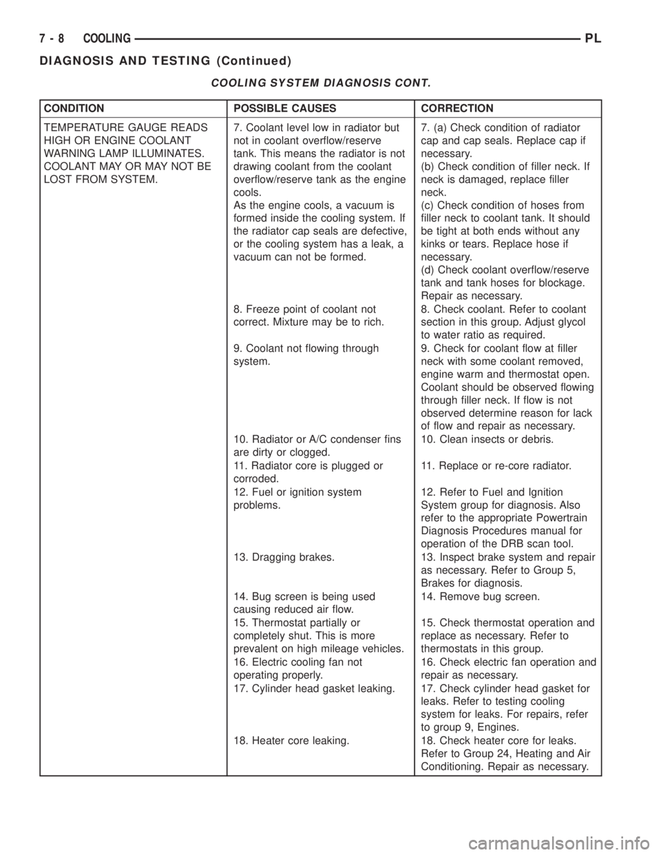
COOLING SYSTEM DIAGNOSIS CONT.
CONDITION POSSIBLE CAUSES CORRECTION
TEMPERATURE GAUGE READS
HIGH OR ENGINE COOLANT
WARNING LAMP ILLUMINATES.
COOLANT MAY OR MAY NOT BE
LOST FROM SYSTEM.7. Coolant level low in radiator but
not in coolant overflow/reserve
tank. This means the radiator is not
drawing coolant from the coolant
overflow/reserve tank as the engine
cools.
As the engine cools, a vacuum is
formed inside the cooling system. If
the radiator cap seals are defective,
or the cooling system has a leak, a
vacuum can not be formed.7. (a) Check condition of radiator
cap and cap seals. Replace cap if
necessary.
(b) Check condition of filler neck. If
neck is damaged, replace filler
neck.
(c) Check condition of hoses from
filler neck to coolant tank. It should
be tight at both ends without any
kinks or tears. Replace hose if
necessary.
(d) Check coolant overflow/reserve
tank and tank hoses for blockage.
Repair as necessary.
8. Freeze point of coolant not
correct. Mixture may be to rich.8. Check coolant. Refer to coolant
section in this group. Adjust glycol
to water ratio as required.
9. Coolant not flowing through
system.9. Check for coolant flow at filler
neck with some coolant removed,
engine warm and thermostat open.
Coolant should be observed flowing
through filler neck. If flow is not
observed determine reason for lack
of flow and repair as necessary.
10. Radiator or A/C condenser fins
are dirty or clogged.10. Clean insects or debris.
11. Radiator core is plugged or
corroded.11. Replace or re-core radiator.
12. Fuel or ignition system
problems.12. Refer to Fuel and Ignition
System group for diagnosis. Also
refer to the appropriate Powertrain
Diagnosis Procedures manual for
operation of the DRB scan tool.
13. Dragging brakes. 13. Inspect brake system and repair
as necessary. Refer to Group 5,
Brakes for diagnosis.
14. Bug screen is being used
causing reduced air flow.14. Remove bug screen.
15. Thermostat partially or
completely shut. This is more
prevalent on high mileage vehicles.15. Check thermostat operation and
replace as necessary. Refer to
thermostats in this group.
16. Electric cooling fan not
operating properly.16. Check electric fan operation and
repair as necessary.
17. Cylinder head gasket leaking. 17. Check cylinder head gasket for
leaks. Refer to testing cooling
system for leaks. For repairs, refer
to group 9, Engines.
18. Heater core leaking. 18. Check heater core for leaks.
Refer to Group 24, Heating and Air
Conditioning. Repair as necessary.
7 - 8 COOLINGPL
DIAGNOSIS AND TESTING (Continued)
Page 208 of 1200
There may be internal leaks, which can be deter-
mined by removing the oil dipstick. If water globules
appear intermixed with the oil, it indicates an inter-
nal leak in the engine. If there is an internal leak,
the engine must be disassembled for repair.
PRESSURE CAP TO FILLER NECK SEAL
PRESSURE RELIEF CHECK
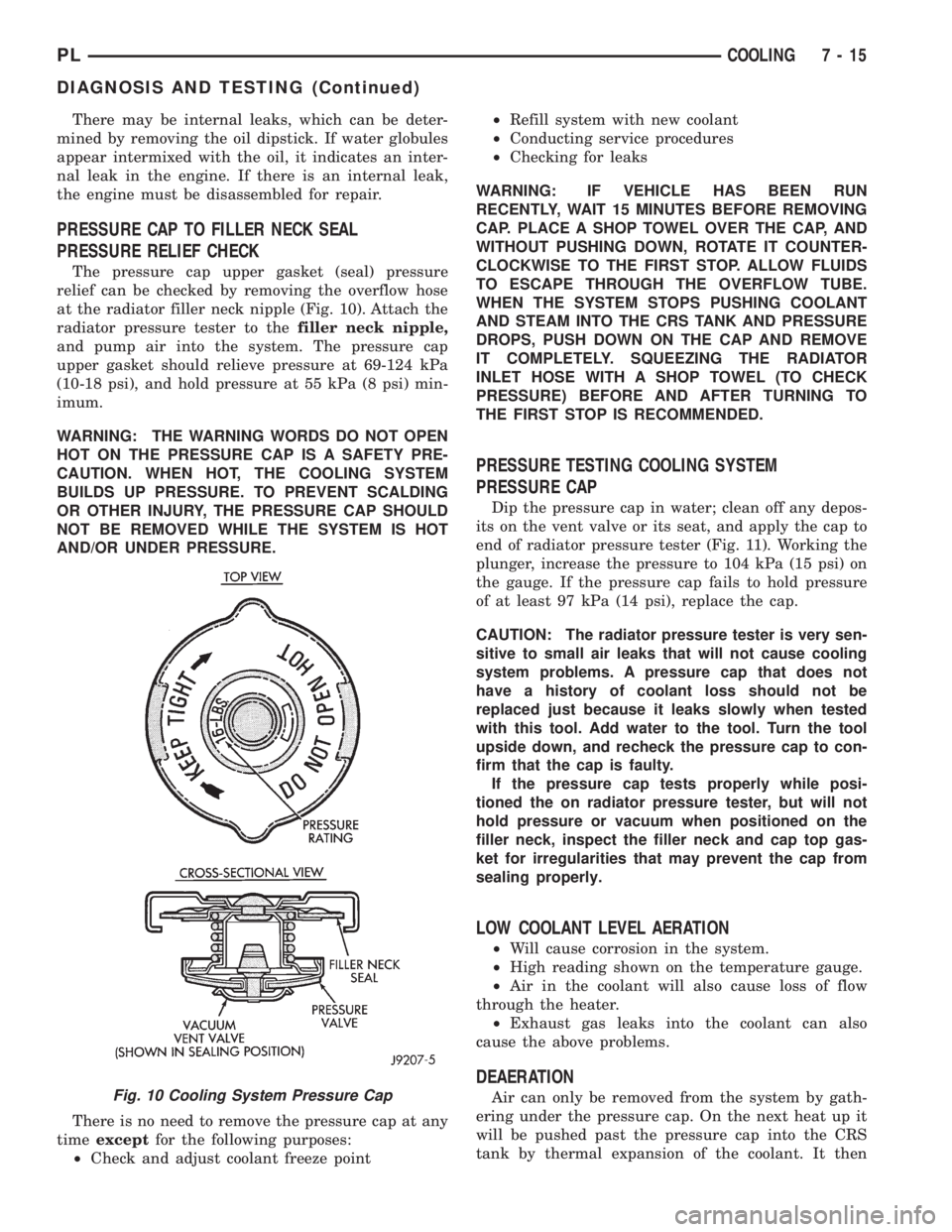
The pressure cap upper gasket (seal) pressure
relief can be checked by removing the overflow hose
at the radiator filler neck nipple (Fig. 10). Attach the
radiator pressure tester to thefiller neck nipple,
and pump air into the system. The pressure cap
upper gasket should relieve pressure at 69-124 kPa
(10-18 psi), and hold pressure at 55 kPa (8 psi) min-
imum.
WARNING: THE WARNING WORDS DO NOT OPEN
HOT ON THE PRESSURE CAP IS A SAFETY PRE-
CAUTION. WHEN HOT, THE COOLING SYSTEM
BUILDS UP PRESSURE. TO PREVENT SCALDING
OR OTHER INJURY, THE PRESSURE CAP SHOULD
NOT BE REMOVED WHILE THE SYSTEM IS HOT
AND/OR UNDER PRESSURE.
There is no need to remove the pressure cap at any
timeexceptfor the following purposes:
²Check and adjust coolant freeze point²Refill system with new coolant
²Conducting service procedures
²Checking for leaks
WARNING: IF VEHICLE HAS BEEN RUN
RECENTLY, WAIT 15 MINUTES BEFORE REMOVING
CAP. PLACE A SHOP TOWEL OVER THE CAP, AND
WITHOUT PUSHING DOWN, ROTATE IT COUNTER-
CLOCKWISE TO THE FIRST STOP. ALLOW FLUIDS
TO ESCAPE THROUGH THE OVERFLOW TUBE.
WHEN THE SYSTEM STOPS PUSHING COOLANT
AND STEAM INTO THE CRS TANK AND PRESSURE
DROPS, PUSH DOWN ON THE CAP AND REMOVE
IT COMPLETELY. SQUEEZING THE RADIATOR
INLET HOSE WITH A SHOP TOWEL (TO CHECK
PRESSURE) BEFORE AND AFTER TURNING TO
THE FIRST STOP IS RECOMMENDED.
PRESSURE TESTING COOLING SYSTEM
PRESSURE CAP
Dip the pressure cap in water; clean off any depos-
its on the vent valve or its seat, and apply the cap to
end of radiator pressure tester (Fig. 11). Working the
plunger, increase the pressure to 104 kPa (15 psi) on
the gauge. If the pressure cap fails to hold pressure
of at least 97 kPa (14 psi), replace the cap.
CAUTION: The radiator pressure tester is very sen-
sitive to small air leaks that will not cause cooling
system problems. A pressure cap that does not
have a history of coolant loss should not be
replaced just because it leaks slowly when tested
with this tool. Add water to the tool. Turn the tool
upside down, and recheck the pressure cap to con-
firm that the cap is faulty.
If the pressure cap tests properly while posi-
tioned the on radiator pressure tester, but will not
hold pressure or vacuum when positioned on the
filler neck, inspect the filler neck and cap top gas-
ket for irregularities that may prevent the cap from
sealing properly.
LOW COOLANT LEVEL AERATION
²Will cause corrosion in the system.
²High reading shown on the temperature gauge.
²Air in the coolant will also cause loss of flow
through the heater.
²Exhaust gas leaks into the coolant can also
cause the above problems.
DEAERATION
Air can only be removed from the system by gath-
ering under the pressure cap. On the next heat up it
will be pushed past the pressure cap into the CRS
tank by thermal expansion of the coolant. It thenFig. 10 Cooling System Pressure Cap
PLCOOLING 7 - 15
DIAGNOSIS AND TESTING (Continued)
Page 845 of 1200
ELECTRIC FUEL PUMP
The electric fuel pump is located in and is part of
the fuel pump module. It is a positive displacement,
gerotor type, immersible pump with a permanent
magnet electric motor. The fuel pump module is sus-
pended in fuel in the fuel tank. The pump draws fuel
through a strainer and pushes it through the motor
to the outlet. The pump contains a check valve. The
valve, in the pump outlet, maintains pump pressure
during engine off conditions. The fuel pump relay
provides voltage to the fuel pump.
The fuel pump has a maximum deadheaded pres-
sure output of approximately 880 kPa (130 psi). The
regulator adjusts fuel system pressure to approxi-
mately 338 kPa (49 psi).
FUEL GAUGE SENDING UNIT
The fuel gauge sending unit (fuel level sensor) is
attached to the side of the fuel pump module. The
sending unit consists of a float, an arm, and a vari-
able resistor (track). The resistor track is used to
send electrical signals to the Powertrain Control
Module (PCM) for fuel gauge operation and for OBD
II emission requirements.
For fuel gauge operation:As fuel level
increases, the float and arm move up. This decreases
the sending unit resistance, causing the fuel gauge to
read full. As fuel level decreases, the float and arm
move down. This increases the sending unit resis-
tance causing the fuel gauge to read empty.
After this fuel level signal is sent to the PCM, the
PCM will transmit the data across the CCD bus cir-
cuits to the instrument panel. Here it is translated
into the appropriate fuel gauge level reading.
FUEL FILTER/FUEL PRESSURE REGULATOR
A combination fuel filter and fuel pressure regula-
tor is used on all gas powered engines. It is located
on the top of the fuel pump module. A separate frame
mounted fuel filter is not used.
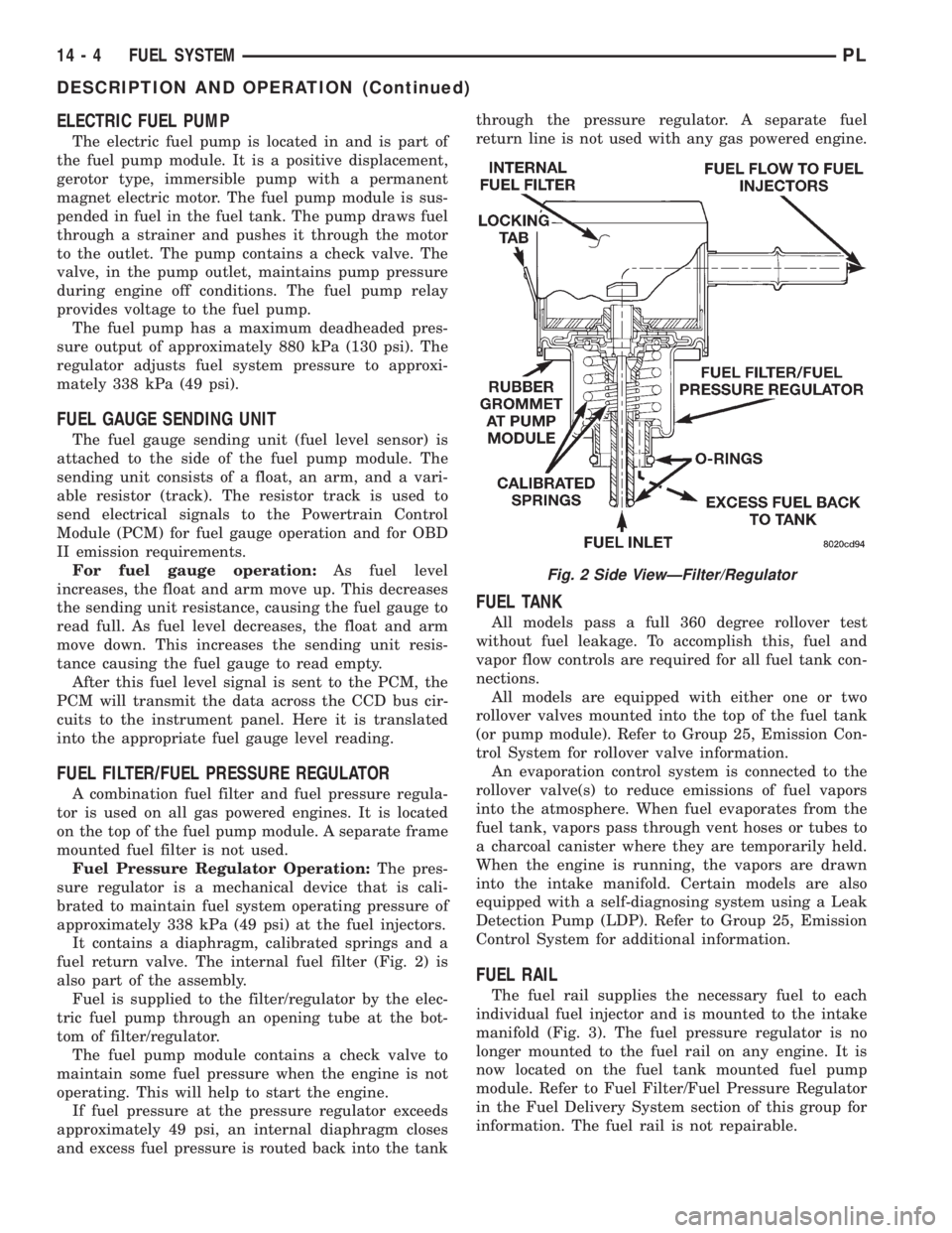
Fuel Pressure Regulator Operation:The pres-
sure regulator is a mechanical device that is cali-
brated to maintain fuel system operating pressure of
approximately 338 kPa (49 psi) at the fuel injectors.
It contains a diaphragm, calibrated springs and a
fuel return valve. The internal fuel filter (Fig. 2) is
also part of the assembly.
Fuel is supplied to the filter/regulator by the elec-
tric fuel pump through an opening tube at the bot-
tom of filter/regulator.
The fuel pump module contains a check valve to
maintain some fuel pressure when the engine is not
operating. This will help to start the engine.
If fuel pressure at the pressure regulator exceeds
approximately 49 psi, an internal diaphragm closes
and excess fuel pressure is routed back into the tankthrough the pressure regulator. A separate fuel
return line is not used with any gas powered engine.
FUEL TANK
All models pass a full 360 degree rollover test
without fuel leakage. To accomplish this, fuel and
vapor flow controls are required for all fuel tank con-
nections.
All models are equipped with either one or two
rollover valves mounted into the top of the fuel tank
(or pump module). Refer to Group 25, Emission Con-
trol System for rollover valve information.
An evaporation control system is connected to the
rollover valve(s) to reduce emissions of fuel vapors
into the atmosphere. When fuel evaporates from the
fuel tank, vapors pass through vent hoses or tubes to
a charcoal canister where they are temporarily held.
When the engine is running, the vapors are drawn
into the intake manifold. Certain models are also
equipped with a self-diagnosing system using a Leak
Detection Pump (LDP). Refer to Group 25, Emission
Control System for additional information.
FUEL RAIL
The fuel rail supplies the necessary fuel to each
individual fuel injector and is mounted to the intake
manifold (Fig. 3). The fuel pressure regulator is no
longer mounted to the fuel rail on any engine. It is
now located on the fuel tank mounted fuel pump
module. Refer to Fuel Filter/Fuel Pressure Regulator
in the Fuel Delivery System section of this group for
information. The fuel rail is not repairable.
Fig. 2 Side ViewÐFilter/Regulator
14 - 4 FUEL SYSTEMPL
DESCRIPTION AND OPERATION (Continued)
Page 851 of 1200
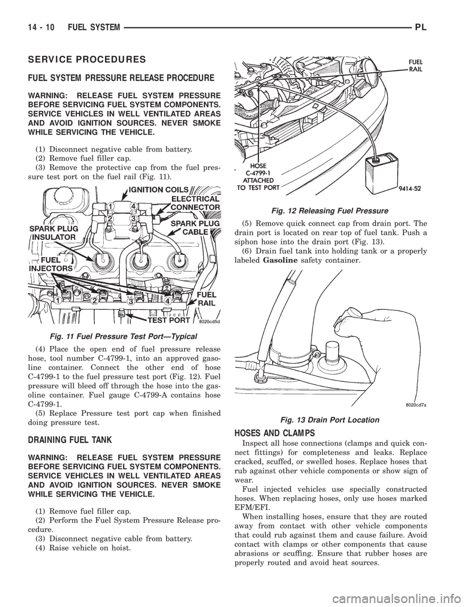
SERVICE PROCEDURES
FUEL SYSTEM PRESSURE RELEASE PROCEDURE
WARNING: RELEASE FUEL SYSTEM PRESSURE
BEFORE SERVICING FUEL SYSTEM COMPONENTS.
SERVICE VEHICLES IN WELL VENTILATED AREAS
AND AVOID IGNITION SOURCES. NEVER SMOKE
WHILE SERVICING THE VEHICLE.
(1) Disconnect negative cable from battery.
(2) Remove fuel filler cap.
(3) Remove the protective cap from the fuel pres-
sure test port on the fuel rail (Fig. 11).
(4) Place the open end of fuel pressure release
hose, tool number C-4799-1, into an approved gaso-
line container. Connect the other end of hose
C-4799-1 to the fuel pressure test port (Fig. 12). Fuel
pressure will bleed off through the hose into the gas-
oline container. Fuel gauge C-4799-A contains hose
C-4799-1.
(5) Replace Pressure test port cap when finished
doing pressure test.
DRAINING FUEL TANK
WARNING: RELEASE FUEL SYSTEM PRESSURE
BEFORE SERVICING FUEL SYSTEM COMPONENTS.
SERVICE VEHICLES IN WELL VENTILATED AREAS
AND AVOID IGNITION SOURCES. NEVER SMOKE
WHILE SERVICING THE VEHICLE.
(1) Remove fuel filler cap.
(2) Perform the Fuel System Pressure Release pro-
cedure.
(3) Disconnect negative cable from battery.
(4) Raise vehicle on hoist.(5) Remove quick connect cap from drain port. The
drain port is located on rear top of fuel tank. Push a
siphon hose into the drain port (Fig. 13).
(6) Drain fuel tank into holding tank or a properly
labeledGasolinesafety container.
HOSES AND CLAMPS
Inspect all hose connections (clamps and quick con-
nect fittings) for completeness and leaks. Replace
cracked, scuffed, or swelled hoses. Replace hoses that
rub against other vehicle components or show sign of
wear.
Fuel injected vehicles use specially constructed
hoses. When replacing hoses, only use hoses marked
EFM/EFI.
When installing hoses, ensure that they are routed
away from contact with other vehicle components
that could rub against them and cause failure. Avoid
contact with clamps or other components that cause
abrasions or scuffing. Ensure that rubber hoses are
properly routed and avoid heat sources.
Fig. 11 Fuel Pressure Test PortÐTypical
Fig. 12 Releasing Fuel Pressure
Fig. 13 Drain Port Location
14 - 10 FUEL SYSTEMPL
Page 856 of 1200

(5) Remove fuel rail mounting screws.
(6) Lift rail off of intake manifold. Cover the fuel
injector openings in the intake manifold.
(7) Remove fuel injector retainer (Fig. 28).
(8) Pull injector out of fuel rail. Replace fuel injec-
tor O-rings (Fig. 29).
INSTALLATION
(1) Apply a light coating of clean engine oil to the
upper O-ring.(2) Install injector in cup on fuel rail.
(3) Install retaining clip.
(4) Apply a light coating of clean engine oil to the
O-ring on the nozzle end of each injector.
(5) Insert fuel injector nozzles into openings in
intake manifold. Seat the injectors in place. Tighten
fuel rail mounting screws to 22.5 N´m63 N´m
(200630 in. lbs.).
(6) Attach electrical connectors to fuel injectors.
(7) Connect fuel supply tube to fuel rail. Refer to
Quick Connect Fittings in the Fuel Delivery Section
of this Group.
FUEL TANK
REMOVAL
(1) Perform fuel system pressure release.
(2) Drain fuel tank. Refer to Draining Fuel Tank
in this section (Fig. 30).
(3) Raise vehicle on hoist.
WARNING: WRAP SHOP TOWELS AROUND
HOSES TO CATCH ANY GASOLINE SPILLAGE.
(4) Disconnect fuel pump module electrical connec-
tor (Fig. 31).
(5) Disconnect the fuel tube from Fuel Filter/Reg-
ulator. Refer to Quick Connect Fittings in the Fuel
Delivery section of this group.
(6) Support tank with transmission jack. Loosen
tank mounting straps and lower tank slightly.
(7) Disconnect fuel filler tube and filler vent tube
from filler hose at fuel tank (Fig. 32).
(8) Disconnect fuel filler vapor relief tube from tee
connecting it to the tank vapor relief tube and EVAP
canister tube.
(9) Disconnect vapor line from Evap canister tube.
(10) Remove tank mounting straps and lower tank.Fig. 27 Fuel Rail and Injectors
Fig. 28 Fuel Injector Retainer
Fig. 29 Fuel Injector O-Rings
Fig. 30 Fuel Tank
PLFUEL SYSTEM 14 - 15
REMOVAL AND INSTALLATION (Continued)