coolant level DODGE NEON 1999 Service User Guide
[x] Cancel search | Manufacturer: DODGE, Model Year: 1999, Model line: NEON, Model: DODGE NEON 1999Pages: 1200, PDF Size: 35.29 MB
Page 210 of 1200
COOLING SYSTEMÐREFILLING
First clean system to remove old glycol, see Cooling
System Cleaning.
Fill system using antifreeze described in Coolant
section. Fill 50 percent of capacity with 100 percent
glycol. Then complete filling system with water.
Continue filling system until full, this provides bet-
ter heater performance.Be careful not to spill
coolant on drive belts or the generator.
Fill coolant reserve system to at least the FULL
mark with 50/50 solution. It may be necessary to add
coolant to the reserve tank after three or four warm-
up/cool down cycles to maintain coolant level between
the FULL and ADD marks; if any trapped air was
removed from the system.
REMOVAL AND INSTALLATION
WATER PUMP
REMOVAL
(1) Raise vehicle on a hoist. Remove right inner
splash shield.
(2) Remove accessory drive belts and power steer-
ing pump. Refer to Accessory Drive Belt service in
this section.
(3) Drain cooling system. Refer to Cooling System
Draining in this section.
(4) Support engine from the bottom and remove
right engine mount.
(5) Remove power steering pump bracket bolts and
set pump and bracket assembly aside. Power steering
lines do not need to be disconnected.
(6) Remove right engine mount bracket.
(7) Remove timing belt and timing belt tensioner.
Refer to Group 9, Engine for procedure.
(8) Remove camshaft sprockets and inner timing
belt cover. Refer to Group 9, Engine for procedure.(9) Remove water pump attaching screws to engine
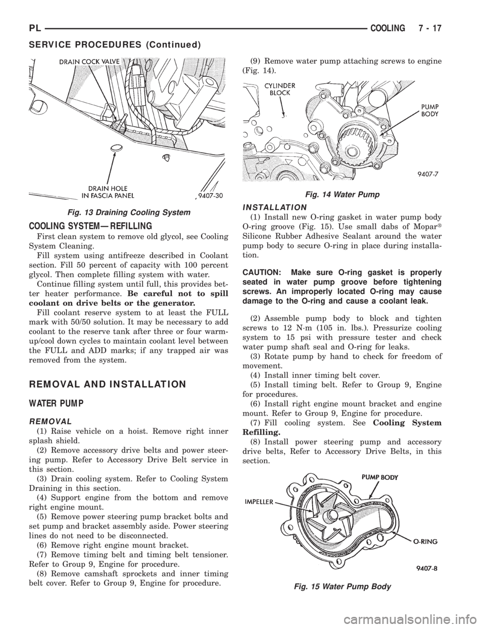
(Fig. 14).
INSTALLATION
(1) Install new O-ring gasket in water pump body
O-ring groove (Fig. 15). Use small dabs of Mopart
Silicone Rubber Adhesive Sealant around the water
pump body to secure O-ring in place during installa-
tion.
CAUTION: Make sure O-ring gasket is properly
seated in water pump groove before tightening
screws. An improperly located O-ring may cause
damage to the O-ring and cause a coolant leak.
(2) Assemble pump body to block and tighten
screws to 12 N´m (105 in. lbs.). Pressurize cooling
system to 15 psi with pressure tester and check
water pump shaft seal and O-ring for leaks.
(3) Rotate pump by hand to check for freedom of
movement.
(4) Install inner timing belt cover.
(5) Install timing belt. Refer to Group 9, Engine
for procedures.
(6) Install right engine mount bracket and engine
mount. Refer to Group 9, Engine for procedure.
(7) Fill cooling system. SeeCooling System
Refilling.
(8) Install power steering pump and accessory
drive belts, Refer to Accessory Drive Belts, in this
section.Fig. 13 Draining Cooling System
Fig. 14 Water Pump
Fig. 15 Water Pump Body
PLCOOLING 7 - 17
SERVICE PROCEDURES (Continued)
Page 211 of 1200
(9) Perform camshaft and crankshaft timing
relearn procedure as follows:
²Connect the DRB scan tool to the data link
(diagnostic) connector. This connector is located in
the passenger compartment; at the lower edge of
instrument panel; near the steering column.
²Turn the ignition switch on and access the ªmis-
cellaneousº screen.
²Select ªre-learn cam/crankº option and follow
directions on DRB screen.
WATER PUMP INLET TUBE
The inlet tube connects the water pump to the
radiator and heater core. This tube is sealed by a
O-ring and held in place by fasteners to the block.
REMOVAL
CAUTION: Do not use any sharp tools to remove
hoses from inlet tube. This may cause the tube to
leak.
(1) Drain cooling system. Refer to procedure out-
lined in this section.
(2) Remove upper radiator hose to access the hose
connections at the inlet tube.
(3) Remove lower radiator hose and heater hose
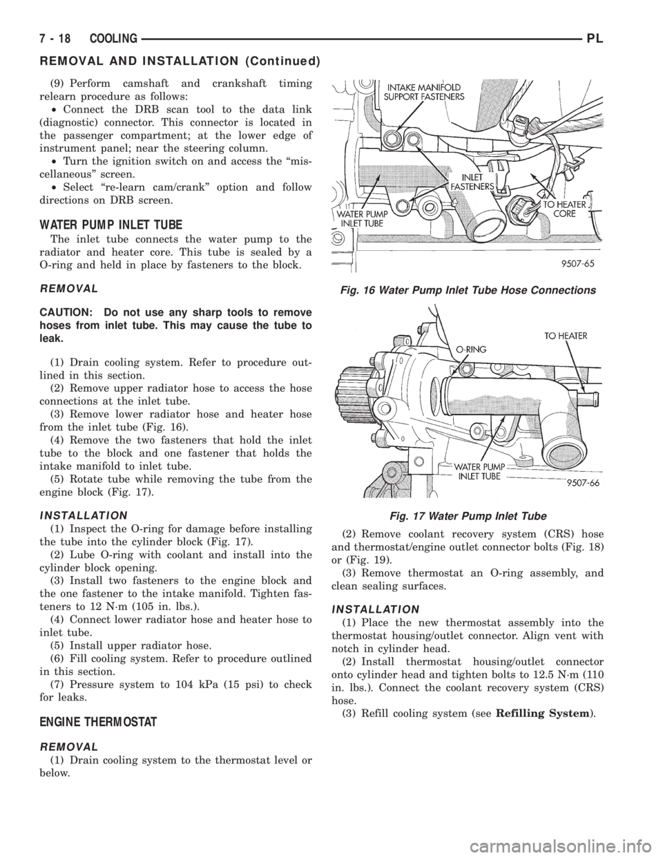
from the inlet tube (Fig. 16).
(4) Remove the two fasteners that hold the inlet
tube to the block and one fastener that holds the
intake manifold to inlet tube.
(5) Rotate tube while removing the tube from the
engine block (Fig. 17).
INSTALLATION
(1) Inspect the O-ring for damage before installing
the tube into the cylinder block (Fig. 17).
(2) Lube O-ring with coolant and install into the
cylinder block opening.
(3) Install two fasteners to the engine block and
the one fastener to the intake manifold. Tighten fas-
teners to 12 N´m (105 in. lbs.).
(4) Connect lower radiator hose and heater hose to
inlet tube.
(5) Install upper radiator hose.
(6) Fill cooling system. Refer to procedure outlined
in this section.
(7) Pressure system to 104 kPa (15 psi) to check
for leaks.
ENGINE THERMOSTAT
REMOVAL
(1) Drain cooling system to the thermostat level or
below.(2) Remove coolant recovery system (CRS) hose
and thermostat/engine outlet connector bolts (Fig. 18)
or (Fig. 19).
(3) Remove thermostat an O-ring assembly, and
clean sealing surfaces.
INSTALLATION
(1) Place the new thermostat assembly into the
thermostat housing/outlet connector. Align vent with
notch in cylinder head.
(2) Install thermostat housing/outlet connector
onto cylinder head and tighten bolts to 12.5 N´m (110
in. lbs.). Connect the coolant recovery system (CRS)
hose.
(3) Refill cooling system (seeRefilling System).
Fig. 16 Water Pump Inlet Tube Hose Connections
Fig. 17 Water Pump Inlet Tube
7 - 18 COOLINGPL
REMOVAL AND INSTALLATION (Continued)
Page 213 of 1200
(5) Connect automatic transmission hoses, if
equipped. Tighten hose clamps to 4 N´m (35 in. lbs.).
(6) Slide fan module down into clip(s) on lower
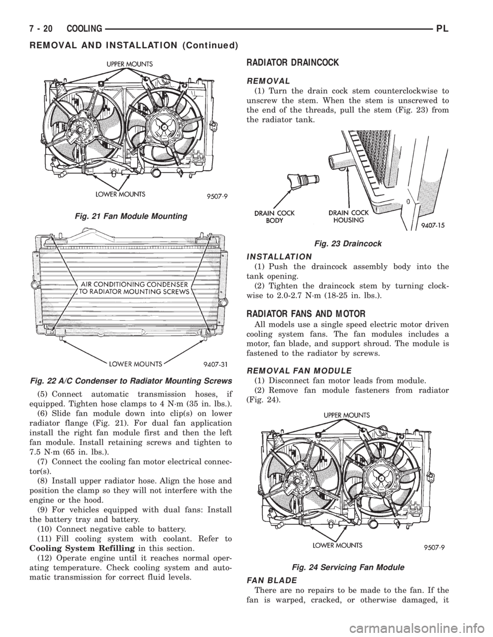
radiator flange (Fig. 21). For dual fan application
install the right fan module first and then the left
fan module. Install retaining screws and tighten to
7.5 N´m (65 in. lbs.).
(7) Connect the cooling fan motor electrical connec-
tor(s).
(8) Install upper radiator hose. Align the hose and
position the clamp so they will not interfere with the
engine or the hood.
(9) For vehicles equipped with dual fans: Install
the battery tray and battery.
(10) Connect negative cable to battery.
(11) Fill cooling system with coolant. Refer to
Cooling System Refillingin this section.
(12) Operate engine until it reaches normal oper-
ating temperature. Check cooling system and auto-
matic transmission for correct fluid levels.
RADIATOR DRAINCOCK
REMOVAL
(1) Turn the drain cock stem counterclockwise to
unscrew the stem. When the stem is unscrewed to
the end of the threads, pull the stem (Fig. 23) from
the radiator tank.
INSTALLATION
(1) Push the draincock assembly body into the
tank opening.
(2) Tighten the draincock stem by turning clock-
wise to 2.0-2.7 N´m (18-25 in. lbs.).
RADIATOR FANS AND MOTOR
All models use a single speed electric motor driven
cooling system fans. The fan modules includes a
motor, fan blade, and support shroud. The module is
fastened to the radiator by screws.
REMOVAL FAN MODULE
(1) Disconnect fan motor leads from module.
(2) Remove fan module fasteners from radiator
(Fig. 24).
FAN BLADE
There are no repairs to be made to the fan. If the
fan is warped, cracked, or otherwise damaged, it
Fig. 21 Fan Module Mounting
Fig. 22 A/C Condenser to Radiator Mounting Screws
Fig. 23 Draincock
Fig. 24 Servicing Fan Module
7 - 20 COOLINGPL
REMOVAL AND INSTALLATION (Continued)
Page 214 of 1200
must be replaced withonlythe recommended part
for adequate strength, performance and safety.
(1) To remove fan from motor shaft, bench support
the motor and motor shaft, while removing the fan
retaining clip, so that the shaft and motor will not be
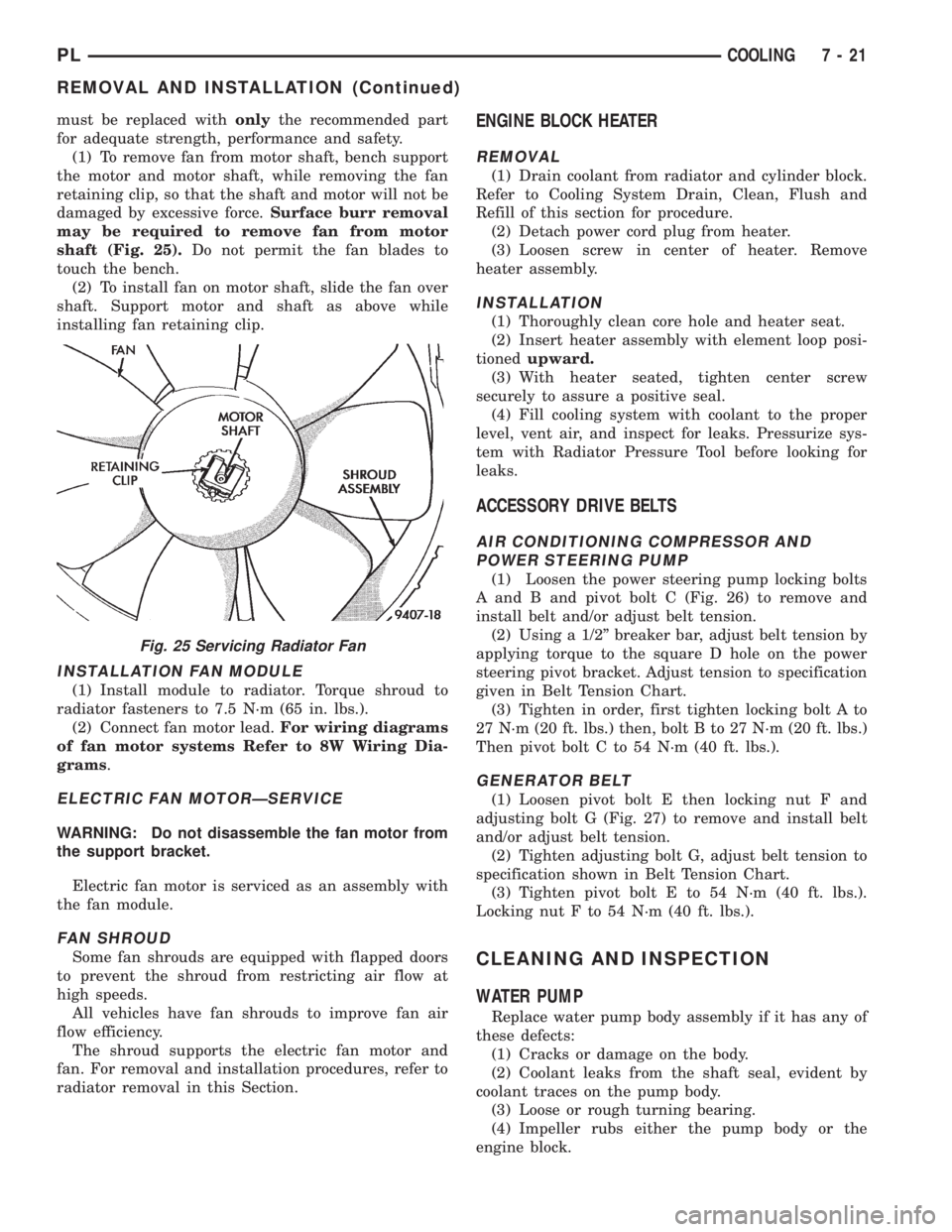
damaged by excessive force.Surface burr removal
may be required to remove fan from motor
shaft (Fig. 25).Do not permit the fan blades to
touch the bench.
(2) To install fan on motor shaft, slide the fan over
shaft. Support motor and shaft as above while
installing fan retaining clip.
INSTALLATION FAN MODULE
(1) Install module to radiator. Torque shroud to
radiator fasteners to 7.5 N´m (65 in. lbs.).
(2) Connect fan motor lead.For wiring diagrams
of fan motor systems Refer to 8W Wiring Dia-
grams.
ELECTRIC FAN MOTORÐSERVICE
WARNING: Do not disassemble the fan motor from
the support bracket.
Electric fan motor is serviced as an assembly with
the fan module.
FAN SHROUD
Some fan shrouds are equipped with flapped doors
to prevent the shroud from restricting air flow at
high speeds.
All vehicles have fan shrouds to improve fan air
flow efficiency.
The shroud supports the electric fan motor and
fan. For removal and installation procedures, refer to
radiator removal in this Section.
ENGINE BLOCK HEATER
REMOVAL
(1) Drain coolant from radiator and cylinder block.
Refer to Cooling System Drain, Clean, Flush and
Refill of this section for procedure.
(2) Detach power cord plug from heater.
(3) Loosen screw in center of heater. Remove
heater assembly.
INSTALLATION
(1) Thoroughly clean core hole and heater seat.
(2) Insert heater assembly with element loop posi-
tionedupward.
(3) With heater seated, tighten center screw
securely to assure a positive seal.
(4) Fill cooling system with coolant to the proper
level, vent air, and inspect for leaks. Pressurize sys-
tem with Radiator Pressure Tool before looking for
leaks.
ACCESSORY DRIVE BELTS
AIR CONDITIONING COMPRESSOR AND
POWER STEERING PUMP
(1) Loosen the power steering pump locking bolts
A and B and pivot bolt C (Fig. 26) to remove and
install belt and/or adjust belt tension.
(2) Using a 1/2º breaker bar, adjust belt tension by
applying torque to the square D hole on the power
steering pivot bracket. Adjust tension to specification
given in Belt Tension Chart.
(3) Tighten in order, first tighten locking bolt A to
27 N´m (20 ft. lbs.) then, bolt B to 27 N´m (20 ft. lbs.)
Then pivot bolt C to 54 N´m (40 ft. lbs.).
GENERATOR BELT
(1) Loosen pivot bolt E then locking nut F and
adjusting bolt G (Fig. 27) to remove and install belt
and/or adjust belt tension.
(2) Tighten adjusting bolt G, adjust belt tension to
specification shown in Belt Tension Chart.
(3) Tighten pivot bolt E to 54 N´m (40 ft. lbs.).
Locking nut F to 54 N´m (40 ft. lbs.).
CLEANING AND INSPECTION
WATER PUMP
Replace water pump body assembly if it has any of
these defects:
(1) Cracks or damage on the body.
(2) Coolant leaks from the shaft seal, evident by
coolant traces on the pump body.
(3) Loose or rough turning bearing.
(4) Impeller rubs either the pump body or the
engine block.
Fig. 25 Servicing Radiator Fan
PLCOOLING 7 - 21
REMOVAL AND INSTALLATION (Continued)
Page 264 of 1200
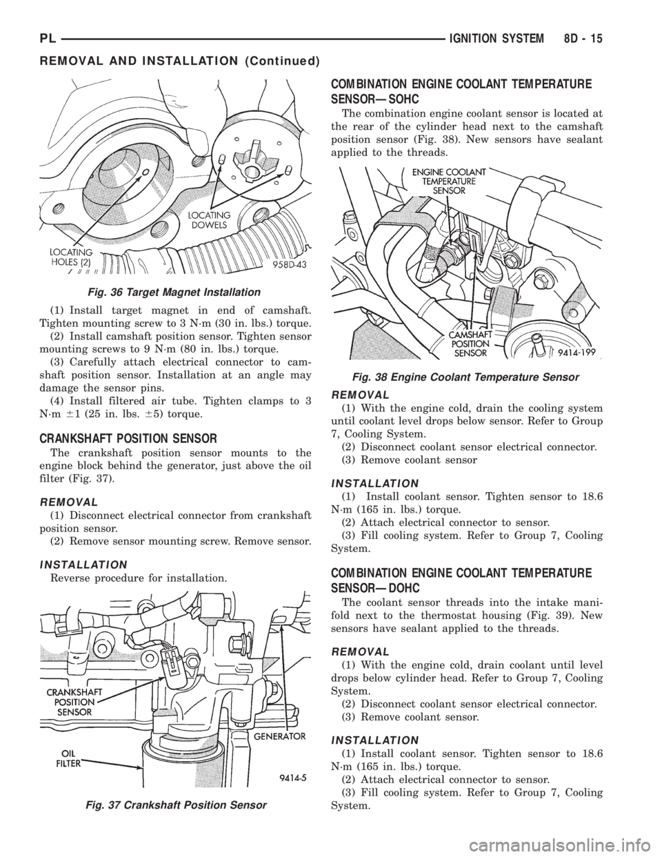
(1) Install target magnet in end of camshaft.
Tighten mounting screw to 3 N´m (30 in. lbs.) torque.
(2) Install camshaft position sensor. Tighten sensor
mounting screws to 9 N´m (80 in. lbs.) torque.
(3) Carefully attach electrical connector to cam-
shaft position sensor. Installation at an angle may
damage the sensor pins.
(4) Install filtered air tube. Tighten clamps to 3
N´m61 (25 in. lbs.65) torque.
CRANKSHAFT POSITION SENSOR
The crankshaft position sensor mounts to the
engine block behind the generator, just above the oil
filter (Fig. 37).
REMOVAL
(1) Disconnect electrical connector from crankshaft
position sensor.
(2) Remove sensor mounting screw. Remove sensor.
INSTALLATION
Reverse procedure for installation.
COMBINATION ENGINE COOLANT TEMPERATURE
SENSORÐSOHC
The combination engine coolant sensor is located at
the rear of the cylinder head next to the camshaft
position sensor (Fig. 38). New sensors have sealant
applied to the threads.
REMOVAL
(1) With the engine cold, drain the cooling system
until coolant level drops below sensor. Refer to Group
7, Cooling System.
(2) Disconnect coolant sensor electrical connector.
(3) Remove coolant sensor
INSTALLATION
(1) Install coolant sensor. Tighten sensor to 18.6
N´m (165 in. lbs.) torque.
(2) Attach electrical connector to sensor.
(3) Fill cooling system. Refer to Group 7, Cooling
System.
COMBINATION ENGINE COOLANT TEMPERATURE
SENSORÐDOHC
The coolant sensor threads into the intake mani-
fold next to the thermostat housing (Fig. 39). New
sensors have sealant applied to the threads.
REMOVAL
(1) With the engine cold, drain coolant until level
drops below cylinder head. Refer to Group 7, Cooling
System.
(2) Disconnect coolant sensor electrical connector.
(3) Remove coolant sensor.
INSTALLATION
(1) Install coolant sensor. Tighten sensor to 18.6
N´m (165 in. lbs.) torque.
(2) Attach electrical connector to sensor.
(3) Fill cooling system. Refer to Group 7, Cooling
System.
Fig. 36 Target Magnet Installation
Fig. 37 Crankshaft Position Sensor
Fig. 38 Engine Coolant Temperature Sensor
PLIGNITION SYSTEM 8D - 15
REMOVAL AND INSTALLATION (Continued)
Page 410 of 1200
8W-02 COMPONENT INDEX
Component Page
A/C Compressor Clutch..................8W-42
A/C Compressor Clutch Relay.............8W-42
A/C Cycling Switch.....................8W-42
A/C Heater Blower Motor................8W-42
A/C Heater Control.....................8W-42
A/C Pressure Switches...................8W-42
ABS Warning Lamp Relay................8W-35
Airbag Control Module...................8W-43
Airbags..............................8W-43
Antenna..............................8W-47
Ash Receiver Lamp.....................8W-44
Automatic Shut Down Relay..............8W-30
Back-Up Lamp Switch...................8W-51
Back-Up Lamps........................8W-51
Battery..............................8W-20
Battery Temperature Sensor..............8W-30
Blower Motor Resistor Block..............8W-42
Brake Warning Lamp Switch...........8W-40, 50
Camshaft Position Sensor................8W-30
Center High Mounted Stop Lamp..........8W-51
Cigar Lighter Relay.....................8W-41
Cigar Lighter/Power Outlet...............8W-41
Circuit Breakers.......................8W-11
Clockspring.....................8W-30, 41, 61
Clutch Pedal Position Switch...........8W-10, 21
Combination Flasher....................8W-52
Controller Anti-Lock Brake...............8W-35
Crankshaft Position Sensor...............8W-30
Data Link Connector....................8W-30
Daytime Running Lamp Module...........8W-50
Diode No. 1........................8W-15, 42
Diode No. 2......................8W-10, 11, 44
Diode No. 3......................8W-11,44,70
Dome Lamp...........................8W-44
Door Ajar Switches.....................8W-44
Door Jamb Switches....................8W-44
Door Lock Motors......................8W-61
Door Lock Motors......................8W-61
Door Lock Switches.....................8W-61
Duty Cycle Evap/Purge Solenoid...........8W-30
EGR Transducer Solenoid................8W-30
Engine Coolant Temperature Sensor........8W-30
Engine Oil Pressure Switch...............8W-40
Engine Starter Motor....................8W-21
Engine Starter Motor Relay...............8W-21
Fog Lamp Relays....................8W-50, 51
Fog Lamp Switches..................8W-50, 51
Fog Lamps.........................8W-50, 51
Fuel Injectors..........................8W-30
Fuel Pump Module.....................8W-30
Fuel Pump Relay.......................8W-30
Fuse Block............................8W-11Component Page
Fuses (FB)............................8W-11
Fuses (PDC)...........................8W-10
Fusible Link........................8W-20, 21
Generator.............................8W-20
Glove Box Lamp And Switch..............8W-44
Grounds..............................8W-15
Halo Lamp............................8W-44
Headlamp Dimmer And Optical Horn Switch .8W-50
Headlamp Leveling Motors...............8W-50
Headlamp Leveling Switch...............8W-50
Headlamp Switch.......................8W-50
Headlamps............................8W-50
High Speed Warning Module..............8W-40
Horn Relay...........................8W-41
Horn Switches.........................8W-41
Horns................................8W-41
IAT/Map Sensor........................8W-30
Idle Air Control Motor...................8W-30
Ignition Coil Pack......................8W-30
Ignition Switch........................8W-10
Illumination Lamps.....................8W-40
Immobilizer...........................8W-61
Immobilizer Engine Sensor............8W-30, 61
Indicator Lamps........................8W-40
Instrument Cluster.....................8W-40
Intermittent Wipe/Wash Switch............8W-53
Key-In Switch.........................8W-40
Knock Sensor..........................8W-30
License Lamps.........................8W-51
Map/Reading Lamps....................8W-44
Noise Supressor.....................8W-10, 30
Oxygen Sensors........................8W-30
Park Brake Switch...................8W-40, 50
Park/Neutral Position Switch...........8W-30, 51
Park/Turn Signal Lamps..............8W-50, 52
Power Distribution Center................8W-10
Power Folding Mirror Relay...............8W-62
Power Mirror Fuse Holder................8W-62
Power Mirrors.........................8W-62
Power Steering Pressure Switch...........8W-30
Power Sunroof Motor....................8W-64
Power Window Motors...................8W-60
Power Window Switches.................8W-60
Powertrain Control Module...............8W-30
PRNDL Lamp.........................8W-44
Radiator Fan Motor.....................8W-42
Radio................................8W-47
Rear Window Defogger..................8W-48
Rear Window Defogger Switch.............8W-48
Remote Keyless Entry Module.............8W-61
Remote Keyless Entry Program
Module Connector....................8W-61
PL8W - 02 COMPONENT INDEX 8W - 02 - 1
Page 499 of 1200
ST-RUN A21FUEL
LEVEL
SENSOR
SIGNAL
INSTRUMENT
CLUSTER
G5
20
DB/WT
G5
20
DB/WT
G5
20
DB/WT
G20
22
VT/YL
G20
20
VT/YL
G20
20
VT/YL
G4
20
DB
Z3
16
BK/OR
Z3
14
BK/OR
G6
22
GY
G6
20
GY
G6
18
GY
S201
SWITCH PRESSURE
OIL
ENGINE
S219BLOCK FUSE
G4
20
DB
G204
8C161
4C103
1C28C1
5C230
3C160
23
10C25C1
1
11
31
POWERTRAIN
CONTROL
MODULE
FUEL
PUMP
MODULESENSOR TEMPERATURE
COOLANT
ENGINE
3G4
18
DB
C1609
C10311
BK/PK20 G3
BK/PK22 G3
BK/PK20 G3
MODULE CONTROL
POWERTRAIN
8
3C2
CHECK
ENGINE
LAMP
DRIVER
3
6
C160
7C103
4C2
RKEOTHER
5A FUSE
11
SENSOR
SIGNAL
ENGINE
COOLANT
TEMPERATURE
GAUGE LAMP ENGINE
CHECK
FUEL
GAUGE
LAMP PRESSURE
OIL
LOW FUEL
LEVEL
SENSOR
SIGNAL
C2
C2
C1056
DB20 G4
(8W-10-9)
(8W-11-15)
(8W-11-16)
(8W-30-12)(8W-30-7)
(8W-30-11)(8W-30-11)
(8W-15-10)
(8W-15-11)(8W-11-2)
(8W-11-3)
(8W-11-4)
(8W-11-15)
(8W-15-10)
(8W-15-11)
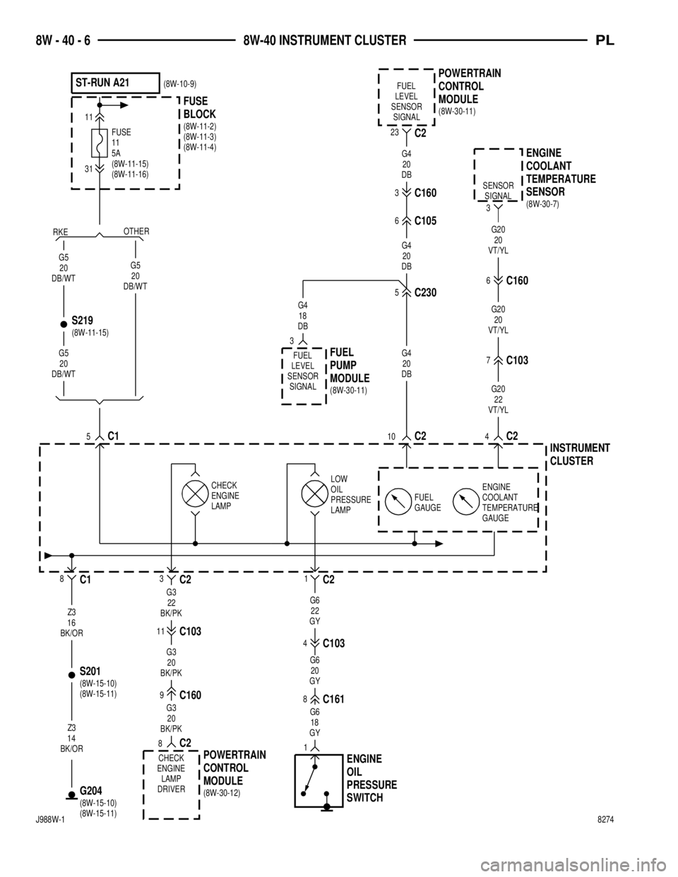
8W - 40 - 6 8W-40 INSTRUMENT CLUSTERPL
J988W-18274
Page 610 of 1200
8W-80 CONNECTOR PIN-OUTS
Component Page
A/C Compressor Clutch.................8W-80-4
A/C Cycling Switch....................8W-80-4
A/C Heater Blower Motor...............8W-80-4
A/C Heater Control....................8W-80-4
A/C High Pressure Switch..............8W-80-4
A/C Low Pressure Switch...............8W-80-5
Airbag Control Module.................8W-80-5
Ash Receiver Lamp....................8W-80-6
Back-Up Lamp Switch.................8W-80-6
Battery Temperature Sensor.............8W-80-6
Blower Motor Resistor Block.............8W-80-6
Brake Warning Lamp Switch............8W-80-6
C101...............................8W-80-7
C102...............................8W-80-7
C103...............................8W-80-7
C104...............................8W-80-8
C105...............................8W-80-8
C108...............................8W-80-8
C160...............................8W-80-8
C161...............................8W-80-8
C170...............................8W-80-9
C205...............................8W-80-9
C206..............................8W-80-10
C225..............................8W-80-10
C230..............................8W-80-10
C231..............................8W-80-11
C241..............................8W-80-12
C242..............................8W-80-12
C301..............................8W-80-12
C303..............................8W-80-12
C309..............................8W-80-12
C340..............................8W-80-13
C341..............................8W-80-13
Camshaft Position Sensor..............8W-80-14
Center High Mounted Stop Lamp........8W-80-14
Cigar Lighter/Power Outlet.............8W-80-14
Clockspring.........................8W-80-14
Clutch Pedal Position Switch...........8W-80-15
Controller Anti-Lock Brake.............8W-80-15
Crankshaft Position Sensor.............8W-80-16
Data Link Connector..................8W-80-1
Daytime Running Lamp Module.........8W-80-16Component Page
Dome Lamp........................8W-80-17
Downstream Heated Oxygen Sensor......8W-80-17
Driver Door Lock Motor...............8W-80-17
Driver Door Lock Switch...............8W-80-17
Driver Power Window Motor............8W-80-17
Driver Power Window Switch...........8W-80-18
Driver Side Airbag...................8W-80-18
Duty Cycle Evap/Purge Solenoid.........8W-80-18
EGR Transducer Solenoid..............8W-80-19
Engine Coolant Temperature Sensor......8W-80-18
Engine Oil Pressure Switch............8W-80-19
Fog Lamp Switch....................8W-80-19
Front Fog Lamp Switch...............8W-80-19
Fuel Injector No. 1...................8W-80-19
Fuel Injector No. 2...................8W-80-19
Fuel Injector No. 3...................8W-80-20
Fuel Injector No. 4...................8W-80-20
Fuel Pump Module...................8W-80-20
Generator..........................8W-80-20
Glove Box Lamp And Switch............8W-80-20
Halo Lamp.........................8W-80-21
Headlamp Dimmer And Optical
Horn Switch......................8W-80-21
Headlamp Leveling Switch.............8W-80-21
Headlamp Switch....................8W-80-21
Heater Blower Motor.................8W-80-21
High Speed Warning Module...........8W-80-22
Horn..............................8W-80-22
Horn No. 1.........................8W-80-22
Horn No. 2.........................8W-80-22
IAT/Map Sensor.....................8W-80-25
Idle Air Control Motor.................8W-80-22
Ignition Coil Pack....................8W-80-22
Ignition Switch......................8W-80-23
Immobilizer.........................8W-80-23
Immobilizer Engine Sensor.............8W-80-23
Instrument Cluster-C1................8W-80-24
Instrument Cluster-C2................8W-80-24
Intermittent Wipe/Wash Switch.........8W-80-25
Key-In Switch.......................8W-80-25
Knock Sensor.......................8W-80-25
PL8W - 80 CONNECTOR PIN-OUTS 8W - 80 - 1
Page 643 of 1200
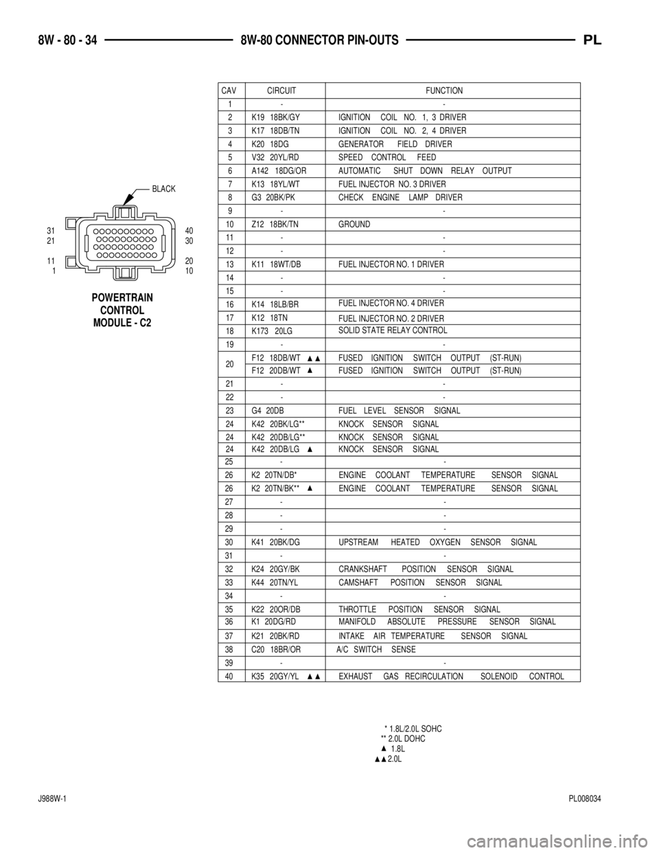
CAV CIRCUIT FUNCTION
1- -
2 K19 18BK/GY IGNITION COIL NO. 1, 3 DRIVER
3 K17 18DB/TN IGNITION COIL NO. 2, 4 DRIVER
4 K20 18DG GENERATOR FIELD DRIVER
5 V32 20YL/RD SPEED CONTROL FEED
6 A142 18DG/OR AUTOMATIC SHUT DOWN RELAY OUTPUT
7 K13 18YL/WT FUEL INJECTOR NO. 3 DRIVER
8 G3 20BK/PK CHECK ENGINE LAMP DRIVER
9- -
10 Z12 18BK/TN GROUND
11 - -
12 - -
13 K11 18WT/DB FUEL INJECTOR NO. 1 DRIVER
14 - -
15 - -
16 K14 18LB/BR
17 K12 18TN
18 K173 20LG
19 - -
20F12 18DB/WT FUSED IGNITION SWITCH OUTPUT (ST-RUN)
21 - -
22 - -
23 G4 20DB FUEL LEVEL SENSOR SIGNAL
24 K42 20BK/LG** KNOCK SENSOR SIGNAL
24 K42 20DB/LG** KNOCK SENSOR SIGNAL
31 40
21 30
11 20
110
BLACK
CONTROL SOLENOID RECIRCULATION GAS EXHAUST 20GY/YL K35 40- - 39
SENSE SWITCH A/C 18BR/OR C20 38
SIGNAL SENSOR POSITION THROTTLE 20OR/DB K22 35
- - 34
SIGNAL SENSOR POSITION CAMSHAFT 20TN/YL K44 33
SIGNAL SENSOR POSITION CRANKSHAFT 20GY/BK K24 32
- - 31
SIGNAL SENSOR OXYGEN HEATED UPSTREAM 20BK/DG K41 30
- - 29
- - 28
- - 27
SIGNAL SENSOR TEMPERATURE COOLANT ENGINE 20TN/BK** K2 26
SIGNAL SENSOR TEMPERATURE COOLANT ENGINE 20TN/DB* K2 26
- - 25
POWERTRAIN
CONTROL
MODULE - C2
20DB/WT F12 (ST-RUN)OUTPUT SWITCH IGNITION FUSED
24K42 20DB/LG KNOCK SENSOR SIGNAL
* 1.8L/2.0L SOHC
** 2.0L DOHC
1.8L
2.0L 36 K1 20DG/RD MANIFOLD ABSOLUTE PRESSURE SENSOR SIGNAL
37 K21 20BK/RD INTAKE AIR TEMPERATURE SENSOR SIGNAL
FUEL INJECTOR NO. 4 DRIVER
FUEL INJECTOR NO. 2 DRIVER
SOLID STATE RELAY CONTROL
8W - 80 - 34 8W-80 CONNECTOR PIN-OUTSPL
J988W-1PL008034
Page 655 of 1200
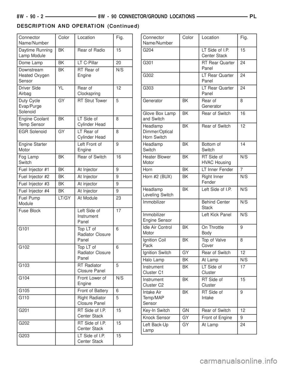
Connector
Name/NumberColor Location Fig.
Daytime Running
Lamp ModuleBK Rear of Radio 15
Dome Lamp BK LT C-Pillar 20
Downstream
Heated Oxygen
SensorBK RT Rear of
EngineN/S
Driver Side
AirbagYL Rear of
Clockspring12
Duty Cycle
Evap/Purge
SolenoidGY RT Strut Tower 5
Engine Coolant
Temp SensorBK LT Side of
Cylinder Head8
EGR Solenoid GY LT Rear of
Cylinder Head8
Engine Starter
MotorLeft Front of
Engine9
Fog Lamp
SwitchBK Rear of Switch 16
Fuel Injector #1 BK At Injector 9
Fuel Injector #2 BK At Injector 9
Fuel Injector #3 BK At injector 9
Fuel Injector #4 BK At Injector 9
Fuel Pump
ModuleLT/GY At Module 23
Fuse Block Left Side of
Instrument
Panel17
G101 Top LT of
Radiator Closure
Panel6
G102 Top LT of
Radiator Closure
Panel6
G103 RT Radiator
Closure Panel5
G104 Front Lower of
EngineN/S
G105 Front of Battery 6
G110 Right Radiator
Closure Panel5
G201 RT Side of I.P.
Center Stack15
G202 RT Side of I.P.
Center Stack15
G203 LT Side of I.P.
Center Stack15
Connector
Name/NumberColor Location Fig.
G204 LT Side of I.P.
Center Stack15
G301 RT Rear Quarter
Panel24
G302 LT Rear Quarter
Panel24
G303 LT Rear Quarter
Panel24
Generator BK Rear of
Generator8
Glove Box Lamp
and SwitchBK Rear of Switch 16
Headlamp
Dimmer/Optical
Horn SwitchBK Rear of Switch 12
Headlamp
SwitchBK Bottom of
Switch14
Heater Blower
MotorBK RT Side of
HVAC HousingN/S
Horn BK LT Inner Fender 7
Horn #2 (BUX) BK Right Inner
FenderN/S
Headlamp
Leveling SwitchBK Left Side of I.P. N/S
Immobilizer Behind Center
StackN/S
Immobilizer
Engine SensorLeft Kick Panel N/S
Idle Air Control
MotorBK On Throttle
Body9
Ignition Coil
PackBK Top of Valve
Cover8
Ignition Switch GY Rear of Switch 12
Halo Lamp BK At Lamp N/S
Instrument
Cluster C1BK LT Side of
Cluster17
Instrument
Cluster C2BK RT Side of
Cluster15
Intake Air
Temp/MAP
SensorBK RT Side of
Intake9
Key-In Switch GN Rear of Switch 12
Knock Sensor GY Front of Engine 9
Left Back-Up
LampGY At Lamp 24
8W - 90 - 2 8W - 90 CONNECTOR/GROUND LOCATIONSPL
DESCRIPTION AND OPERATION (Continued)