headlamp DODGE NEON 1999 Service Owner's Manual
[x] Cancel search | Manufacturer: DODGE, Model Year: 1999, Model line: NEON, Model: DODGE NEON 1999Pages: 1200, PDF Size: 35.29 MB
Page 348 of 1200
LAMP SERVICE
INDEX
page page
GENERAL INFORMATION
HEADLAMP DIMMER SWITCH............... 5
HEADLAMP SWITCH...................... 5
REMOVAL AND INSTALLATION
FOG LAMP.............................. 6HEADLAMP ASSEMBLY.................... 5
HEADLAMP LEVELING MOTOR.............. 6
SIDE REPEATER LAMP.................... 6
GENERAL INFORMATION
HEADLAMP SWITCH
Service procedures for the headlamp switch can be
found in Group 8E, Instrument Panel and Gauges.
More information can be found in Group 8W, Wiring
Diagrams.
HEADLAMP DIMMER SWITCH
The headlamp dimmer switch is incorporated into
the multi-function (turn signal) switch. Proper proce-
dures can be found in Group 8J, Turn Signal and
Flashers. More information can be found in Group
8W, Wiring Diagrams.
REMOVAL AND INSTALLATION
HEADLAMP ASSEMBLY
REMOVAL
(1) Release hood latch and open hood.
(2) Remove headlamp horizontal aim cable from
retainer clip on radiator upper crossmember.
(3) Disengage wire connector from leveling motor.
(4) Remove bolts holding headlamp leveling motor
to the upper radiator crossmember.
(5) Remove plastic locking cap holding vertical lev-
eling cable into leveling motor arm.
(6) Separate leveling cable from motor arm.
(7) Rotate leveling cable case one quarter turn
counter-clockwise and separate cable from motor
bracket.
(8) Separate leveling motor and bracket from vehi-
cle.
(9) From between front fascia and headlamp
assembly, remove bolt holding outboard end of
assembly to fender.
(10) Remove bolts holding inboard end of assembly
to radiator closure panel.
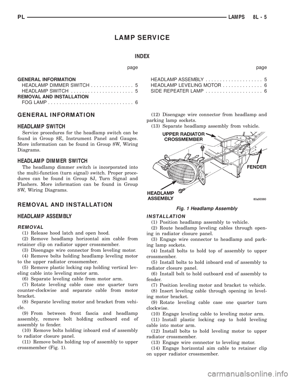
(11) Remove bolts holding top of assembly to upper
crossmember (Fig. 1).(12) Disengage wire connector from headlamp and
parking lamp sockets.
(13) Separate headlamp assembly from vehicle.
INSTALLATION
(1) Position headlamp assembly to vehicle.
(2) Route headlamp leveling cables through open-
ing in radiator closure panel.
(3) Engage wire connector to headlamp and park-
ing lamp sockets.
(4) Install bolts to hold top of assembly to upper
crossmember.
(5) Install bolts to hold inboard end of assembly to
radiator closure panel.
(6) Install bolt to hold outboard end of assembly to
fender.
(7) Position leveling motor and bracket to vehicle.
(8) Insert leveling cable through opening in level-
ing motor bracket.
(9) Rotate leveling cable case one quarter turn
clockwise.
(10) Engage leveling cable to leveling motor arm.
(11) Install plastic locking cap to hold leveling
cable into motor arm.
(12) Install bolts to hold leveling motor to upper
radiator crossmember.
(13) Engage wire connector to leveling motor.
(14) Engage horizontal aim cable to retainer clip
on upper radiator crossmember.
Fig. 1 Headlamp Assembly
PLLAMPS 8L - 5
Page 349 of 1200
(15) Verify lamp operation.
HEADLAMP LEVELING MOTOR
REMOVAL
(1) Disengage wire connector from headlamp level-
ing motor.
(2) Remove bolts holding headlamp leveling motor
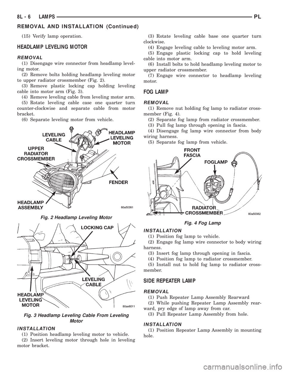
to upper radiator crossmember (Fig. 2).
(3) Remove plastic locking cap holding leveling
cable into motor arm (Fig. 3).
(4) Remove leveling cable from leveling motor arm.
(5) Rotate leveling cable case one quarter turn
counter-clockwise and separate cable from motor
bracket.
(6) Separate leveling motor from vehicle.
INSTALLATION
(1) Position headlamp leveling motor to vehicle.
(2) Insert leveling motor through hole in leveling
motor bracket.(3) Rotate leveling cable base one quarter turn
clockwise.
(4) Engage leveling cable to leveling motor arm.
(5) Engage plastic locking cap to hold leveling
cable into motor arm.
(6) Install bolts to hold headlamp leveling motor to
upper radiator crossmember.
(7) Engage wire connector to headlamp leveling
motor.
FOG LAMP
REMOVAL
(1) Remove nut holding fog lamp to radiator cross-
member (Fig. 4).
(2) Separate fog lamp from radiator crossmember.
(3) Pull fog lamp through opening in fascia.
(4) Disengage fog lamp wire connector from body
wiring harness.
(5) Separate fog lamp from vehicle.
INSTALLATION
(1) Position fog lamp to vehicle.
(2) Engage fog lamp wire connector to body wiring
harness.
(3) Insert fog lamp through opening in fascia.
(4) Position fog lamp to radiator crossmember.
(5) Install nut to hold fog lamp to radiator cross-
member.
SIDE REPEATER LAMP
REMOVAL
(1) Push Repeater Lamp Assembly Rearward
(2) While pushing Repeater Lamp Assembly rear-
ward, pry edge of lamp away from car.
(3) Pull Repeater Lamp Assembly from hole.
INSTALLATION
(1) Position Repeater Lamp Assembly in mounting
hole.
Fig. 2 Headlamp Leveling Motor
Fig. 3 Headlamp Leveling Cable From Leveling
Motor
Fig. 4 Fog Lamp
8L - 6 LAMPSPL
REMOVAL AND INSTALLATION (Continued)
Page 351 of 1200
BULB APPLICATION
INDEX
page page
GENERAL INFORMATION
INTRODUCTION......................... 8
SPECIFICATIONS
EXTERIOR LAMPS........................ 8INTERIOR LAMPS........................ 8
GENERAL INFORMATION
INTRODUCTION
The following Bulb Application Tables list the lamp
title on the left side of the column and trade number
or part number on the right.
CAUTION: Do not use bulbs that have a higher
candle power than the bulb listed in the Bulb Appli-
cation Table. Damage to lamp can result.
Do not touch halogen bulbs with fingers or other
possibly oily surfaces. Bulb life will be reduced.
If a halogen bulb is contaminated with oil, clean
bulb with denatured alcohol or ammonia based sol-
vent.
SPECIFICATIONS
EXTERIOR LAMPS
LAMP BULB
Back-up...............................P21W
Center High Mounted Stop..................921
Front Fog Lamp..........................H-3
Headlamp...............................H-4
License Plate...........................W5W
Front Turn Signal.....................P21/5W
Tail/Stop.............................P21/5W
Rear Turn Signal.......................P21W
Rear Fog Lamp.........................P21W
Citylight...............................T4W
Side Repeater...........................T4W
INTERIOR LAMPS
LAMP BULB
ABS.................................PC194
Airbag...............................PC194
AshTray................................161
Brake Warning System Indicator...........PC194
Cigar Lighter............................203
Climate Controls.........................203
Console Gear Selector......................161
Dome Light..............................578
Glove Box...............................194
High Beam Indicator....................PC194
Ignition Key.............................161
Instrument Cluster.....................PC194
Rear Cargo..............................912
Seat Belt Indicator.......................PC74
Service Engine Soon....................PC194
Turn Signal Indicator....................PC194
Underhood..............................105
Visor Vanity.........................6501966
Volts Indicator..........................PC74
8L - 8 LAMPSPL
Page 372 of 1200
REMOTE KEYLESS ENTRY
INDEX
page page
GENERAL INFORMATION
INTRODUCTION......................... 3
DESCRIPTION AND OPERATION
VEHICLE ACCESS CODE (VAC)
PROGRAMMING........................ 3
DIAGNOSIS AND TESTING
REMOTE KEYLESS ENTRY CONDITION....... 4
REMOTE KEYLESS ENTRY SYSTEM......... 5
SERVICE PROCEDURES
HORN CHIRP CANCELLATION.............. 5PANIC FUNCTION CANCELLATION........... 5
PROGRAM REMOTE KEYLESS ENTRY
MODULE.............................. 5
REMOVAL AND INSTALLATION
REMOTE KEYLESS ENTRY MODULE......... 6
SPECIFICATIONS
RKE TRANSMITTER BATTERY.............. 6
RKE TRANSMITTER RANGE................ 6
GENERAL INFORMATION
INTRODUCTION
The key fob transmitter has three buttons to actu-
ate and program the Remote Keyless Entry (RKE)
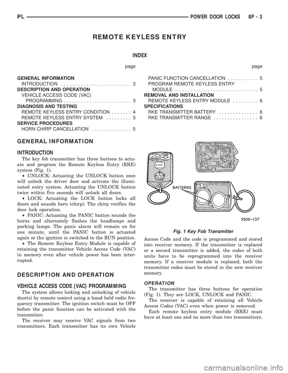
system (Fig. 1).
²UNLOCK: Actuating the UNLOCK button once
will unlock the driver door and activate the illumi-
nated entry system. Actuating the UNLOCK button
twice within five seconds will unlock all doors.
²LOCK: Actuating the LOCK button locks all
doors and sounds horn (chirp). The chirp verifies the
door lock operation.
²PANIC: Actuating the PANIC button sounds the
horns and alternately flashes the headlamps and
parking lamps. The panic alarm will remain on for
one minute, until the PANIC button is actuated
again or the ignition is switched to the RUN position.
²The Remote Keyless Entry Module is capable of
retaining the transmitter Vehicle Access Code (VAC)
in memory even after vehicle power has been inter-
rupted.
DESCRIPTION AND OPERATION
VEHICLE ACCESS CODE (VAC) PROGRAMMING
The system allows locking and unlocking of vehicle
door(s) by remote control using a hand held radio fre-
quency transmitter. The ignition switch must be OFF
before the panic function can be activated with the
transmitter.
The receiver may receive VAC signals from two
transmitters. Each transmitter has its own VehicleAccess Code and the code is programmed and stored
into receiver memory. If the transmitter is replaced
or a second transmitter is added, the codes of both
units have to be reprogrammed into the receiver
memory. If a receiver module is replaced, both the
transmitter codes must be stored in the new receiver
memory.
OPERATION
The transmitter has three buttons for operation
(Fig. 1). They are LOCK, UNLOCK and PANIC.
The receiver is capable of retaining all Vehicle
Access Codes (VAC) even when power is removed.
Each remote keyless entry module (RKE) must
have at least one and no more than two transmitters.
Fig. 1 Key Fob Transmitter
PLPOWER DOOR LOCKS 8P - 3
Page 390 of 1200
CHIME WARNING/REMINDER SYSTEM
CONTENTS
page page
GENERAL INFORMATION
INTRODUCTION......................... 1
DIAGNOSIS AND TESTING
CHIME SYSTEM CONDITIONS.............. 1
FASTEN SEAT BELTS..................... 1
HEADLAMPS LEFT ON.................... 1KEY LEFT IN IGNITION SWITCH............ 1
REMOVAL AND INSTALLATION
CHIME................................. 2
HEADLAMP SWITCH..................... 2
KEY-IN SWITCH......................... 2
SEAT BELT BUCKLE...................... 2
GENERAL INFORMATION
INTRODUCTION
WARNING: ON VEHICLES EQUIPPED WITH AN
AIRBAG, REFER TO THE AIRBAG PORTION OF
THIS SECTION FOR STEERING WHEEL OR SWITCH
REMOVAL AND INSTALLATION PROCEDURES.
The seat belt reminder system uses both visual
and audible signals. A combined seat belt and key
reminder chime with a red light on the instrument
panel.
The system will always illuminate the seat belt
reminder lamp for four to eight seconds when the
ignition switch is turned to the ON position. The
CHIME will sound during the same time interval if
the driver's seat belt is not fastened. Passenger belts
are not connected to the system. The chime will acti-
vate if the drivers door is opened and:
²The key is in the ignition switch, with the igni-
tion switch in either the OFF or accessory (ACC)
position
²The head lamps are ON.
The chime is part of the instrument cluster.
NOTE: This group covers both Left-Hand Drive
(LHD) and Right-Hand Drive (RHD) versions of this
model. Whenever required and feasible, the RHD
versions of affected vehicle components have been
constructed as mirror-image of the LHD versions.
While most of the illustrations used in this group
represent only the LHD version, the diagnostic and
service procedures outlined can generally be
applied to either version. Exceptions to this rule
have been clearly identified as LHD, RHD, or Export
if a special illustration or procedure is required.
DIAGNOSIS AND TESTING
FASTEN SEAT BELTS
To test the fasten seat belts function, turn the igni-
tion switch to the ON position with the driver's seat
belt unbuckled and fully retracted. The seat belt
warning lamp should light for four to eight seconds
and the tone should sound three to five times.
HEADLAMPS LEFT ON
To test the headlamps left on function:
²Turn headlamps
²Driver's door open
²Key removed from the ignition switch
Chime should sound until headlamps are turned
off or driver's door is closed.
KEY LEFT IN IGNITION SWITCH
To test the key left in ignition function, insert key
into the ignition and open driver's door. Chime
should sound until key is removed from ignition or
driver's door is closed.
CHIME SYSTEM CONDITIONS
The cluster harness connector, J1 is car right and
the J2 is car left.
NO TONE WHEN IGNITION SWITCH IS
TURNED ON AND DRIVERS SEAT BELT IS
UNBUCKLED
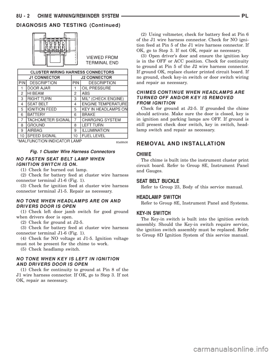
(1) Using an ohmmeter, with the seat belt fully
retracted, check for continuity to ground at Pin 4 of
the J1 wire harness connector (Fig. 1). If OK, go to
step 2. If not OK, repair as necessary .
(2) Check for continuity to ground at Pin 8 of the
J1 wire harness connector. If OK, go to Step 3. If not
OK, repair as necessary.
(3) Using voltmeter, check for battery feed at Pin 6
of the J1 wire harness connector. Check for ignition
feed at Pin 5 of the J1 wire harness connector. If not
OK, repair as necessary.
PLCHIME WARNING/REMINDER SYSTEM 8U - 1
Page 391 of 1200
NO FASTEN SEAT BELT LAMP WHEN
IGNITION SWITCH IS ON.
(1) Check for burned out lamp.
(2) Check for battery feed at cluster wire harness
connector terminal J1-6 (Fig. 1).
(3) Check for ignition feed at cluster wire harness
connector terminal J1-5. Repair as necessary.
NO TONE WHEN HEADLAMPS ARE ON AND
DRIVERS DOOR IS OPEN
(1) Check left door jamb switch for good ground
when drivers door is open.
(2) Check for ground at J2-5.
(3) Check for battery feed at cluster wire harness
connector terminal J1-6 (Fig. 1).
(4) Check for NO voltage at J1-5. Ignition voltage
must not be present for the chime to work.
(5) Check headlamp switch.
NO TONE WHEN KEY IS LEFT IN IGNITION
AND DRIVERS DOOR IS OPEN
(1) Check for continuity to ground at Pin 8 of the
J1 wire harness connector. If OK, go to Step 3. If not
OK, repair as necessary.(2) Using voltmeter, check for battery feed at Pin 6
of the J1 wire harness connector. Check for NO igni-
tion feed at Pin 5 of the J1 wire harness connector. If
OK, go to Step 3. If not OK, repair as necessary.
(3) Open driver's door and ensure the ignition key
is in the OFF or ACC position. Check for continuity
to ground at Pin 5 of the J2 wire harness connector.
If ground OK, replace cluster printed circuit board. If
no ground, check key-in switch or door switch wiring
and repair as necessary.
CHIMES CONTINUE WHEN HEADLAMPS ARE
TURNED OFF AND/OR KEY IS REMOVED
FROM IGNITION
Check for ground at J2-5. If grounded the chime
should activate. Make sure the door is closed, key is
in ignition and parking lamps are OFF. If ground is
still present check door switch, key in switch, head-
lamp switch and repair as necessary.
REMOVAL AND INSTALLATION
CHIME
The chime is built into the instrument cluster print
circuit board. Refer to Group 8E, Instrument Panel
and Gauges.
SEAT BELT BUCKLE
Refer to Group 23, Body of this service manual.
HEADLAMP SWITCH
Refer to Group 8E, Instrument Panel and Systems.
KEY-IN SWITCH
The Key-in switch is built into the ignition switch
assembly. Should the Key-in switch require service,
the ignition switch assembly must be replaced. Refer
to Group 8D Ignition System of this service manual.
Fig. 1 Cluster Wire Harness Connectors
8U - 2 CHIME WARNING/REMINDER SYSTEMPL
DIAGNOSIS AND TESTING (Continued)
Page 410 of 1200
8W-02 COMPONENT INDEX
Component Page
A/C Compressor Clutch..................8W-42
A/C Compressor Clutch Relay.............8W-42
A/C Cycling Switch.....................8W-42
A/C Heater Blower Motor................8W-42
A/C Heater Control.....................8W-42
A/C Pressure Switches...................8W-42
ABS Warning Lamp Relay................8W-35
Airbag Control Module...................8W-43
Airbags..............................8W-43
Antenna..............................8W-47
Ash Receiver Lamp.....................8W-44
Automatic Shut Down Relay..............8W-30
Back-Up Lamp Switch...................8W-51
Back-Up Lamps........................8W-51
Battery..............................8W-20
Battery Temperature Sensor..............8W-30
Blower Motor Resistor Block..............8W-42
Brake Warning Lamp Switch...........8W-40, 50
Camshaft Position Sensor................8W-30
Center High Mounted Stop Lamp..........8W-51
Cigar Lighter Relay.....................8W-41
Cigar Lighter/Power Outlet...............8W-41
Circuit Breakers.......................8W-11
Clockspring.....................8W-30, 41, 61
Clutch Pedal Position Switch...........8W-10, 21
Combination Flasher....................8W-52
Controller Anti-Lock Brake...............8W-35
Crankshaft Position Sensor...............8W-30
Data Link Connector....................8W-30
Daytime Running Lamp Module...........8W-50
Diode No. 1........................8W-15, 42
Diode No. 2......................8W-10, 11, 44
Diode No. 3......................8W-11,44,70
Dome Lamp...........................8W-44
Door Ajar Switches.....................8W-44
Door Jamb Switches....................8W-44
Door Lock Motors......................8W-61
Door Lock Motors......................8W-61
Door Lock Switches.....................8W-61
Duty Cycle Evap/Purge Solenoid...........8W-30
EGR Transducer Solenoid................8W-30
Engine Coolant Temperature Sensor........8W-30
Engine Oil Pressure Switch...............8W-40
Engine Starter Motor....................8W-21
Engine Starter Motor Relay...............8W-21
Fog Lamp Relays....................8W-50, 51
Fog Lamp Switches..................8W-50, 51
Fog Lamps.........................8W-50, 51
Fuel Injectors..........................8W-30
Fuel Pump Module.....................8W-30
Fuel Pump Relay.......................8W-30
Fuse Block............................8W-11Component Page
Fuses (FB)............................8W-11
Fuses (PDC)...........................8W-10
Fusible Link........................8W-20, 21
Generator.............................8W-20
Glove Box Lamp And Switch..............8W-44
Grounds..............................8W-15
Halo Lamp............................8W-44
Headlamp Dimmer And Optical Horn Switch .8W-50
Headlamp Leveling Motors...............8W-50
Headlamp Leveling Switch...............8W-50
Headlamp Switch.......................8W-50
Headlamps............................8W-50
High Speed Warning Module..............8W-40
Horn Relay...........................8W-41
Horn Switches.........................8W-41
Horns................................8W-41
IAT/Map Sensor........................8W-30
Idle Air Control Motor...................8W-30
Ignition Coil Pack......................8W-30
Ignition Switch........................8W-10
Illumination Lamps.....................8W-40
Immobilizer...........................8W-61
Immobilizer Engine Sensor............8W-30, 61
Indicator Lamps........................8W-40
Instrument Cluster.....................8W-40
Intermittent Wipe/Wash Switch............8W-53
Key-In Switch.........................8W-40
Knock Sensor..........................8W-30
License Lamps.........................8W-51
Map/Reading Lamps....................8W-44
Noise Supressor.....................8W-10, 30
Oxygen Sensors........................8W-30
Park Brake Switch...................8W-40, 50
Park/Neutral Position Switch...........8W-30, 51
Park/Turn Signal Lamps..............8W-50, 52
Power Distribution Center................8W-10
Power Folding Mirror Relay...............8W-62
Power Mirror Fuse Holder................8W-62
Power Mirrors.........................8W-62
Power Steering Pressure Switch...........8W-30
Power Sunroof Motor....................8W-64
Power Window Motors...................8W-60
Power Window Switches.................8W-60
Powertrain Control Module...............8W-30
PRNDL Lamp.........................8W-44
Radiator Fan Motor.....................8W-42
Radio................................8W-47
Rear Window Defogger..................8W-48
Rear Window Defogger Switch.............8W-48
Remote Keyless Entry Module.............8W-61
Remote Keyless Entry Program
Module Connector....................8W-61
PL8W - 02 COMPONENT INDEX 8W - 02 - 1
Page 412 of 1200
8W-10 POWER DISTRIBUTION
Component Page
A/C Compressor Clutch.............8W-10-14, 15
A/C Compressor Clutch Relay........8W-10-14, 15
Automatic Shut Down Relay............8W-10-16
Battery...........................8W-10-5, 6
Capacitor..........................8W-10-16
Circuit Breaker.......................8W-10-8
Clutch Pedal Position Switch.......8W-10-9, 10, 11
Controller Anti-Lock Brake.......8W-10-12, 14, 15
Data Link Connector..................8W-10-16
Diode No. 1......................8W-10-14, 15
Diode No. 2.........................8W-10-13
Dome Lamp........................8W-10-13
Downstream Heated Oxygen Sensor......8W-10-16
Engine Starter Motor..................8W-10-7
Engine Starter Motor Relay......8W-10-7, 9, 10, 11
Fog Lamp Relay.....................8W-10-17
Fuel Injector No. 1...................8W-10-16
Fuel Injector No. 2...................8W-10-16
Fuel Injector No. 3...................8W-10-16
Fuel Injector No. 4...................8W-10-16
Fuel Pump Module...................8W-10-16
Fuel Pump Relay....................8W-10-16
Fuse 1 (FB)..........................8W-10-8
Fuse 2 (FB)..........................8W-10-8
Fuse 2 (PDC).....................8W-10-5, 6, 7
Fuse 3 (FB)..........................8W-10-8
Fuse 3 (PDC).....................8W-10-5, 6, 8
Fuse 4 (FB)..........................8W-10-8
Fuse 5 (FB)..........................8W-10-8
Fuse 5 (PDC)....................8W-10-5, 6, 12
Fuse 6 (FB)..........................8W-10-8
Fuse 7 (FB)..........................8W-10-8
Fuse 8 (FB)..........................8W-10-8
Fuse 8 (PDC)....................8W-10-5, 6, 12
Fuse 9 (FB).......................8W-10-9, 10
Fuse 10 (FB)...................8W-10-9, 10, 11
Fuse 10 (PDC)...................8W-10-5, 6, 12
Fuse 11 (FB)...................8W-10-9, 10, 11
Fuse 11 (PDC)....................8W-10-5, 6, 7
Fuse 12 (FB)........................8W-10-11
Fuse 13 (PDC)...................8W-10-5, 6, 13
Fuse 14 (FB)...................8W-10-9, 10, 11
Fuse 15 (FB)...................8W-10-9, 10, 11
Fuse 16 (FB)...................8W-10-9, 10, 11Component Page
Fuse 16 (PDC).....................8W-10-6, 17
Fuse 18 (PDC)................8W-10-5, 6, 14, 15
Fuse 20 (PDC)................8W-10-5, 6, 14, 15
Fuse 21 (PDC)...................8W-10-5, 6, 16
Fuse 23 (PDC)................8W-10-5, 6, 14, 15
Fuse 25 (PDC)................8W-10-5, 6, 14, 15
Fuse Block...................8W-10-8, 9, 10, 11
G101...............................8W-10-9
G204...............................8W-10-7
Generator..........................8W-10-16
Glove Box Lamp And Switch............8W-10-13
Headlamp Switch.....................8W-10-8
High Speed Warning Module...........8W-10-13
Horn..............................8W-10-14
Horn No. 1.........................8W-10-15
Horn No. 2.........................8W-10-15
Horn Relay......................8W-10-14, 15
Ignition Coil Pack....................8W-10-16
Ignition Switch.............8W-10-7, 8, 9, 10, 11
Immobilizer......................8W-10-10, 11
Instrument Cluster.................8W-10-7, 13
Left Fog Lamp......................8W-10-17
Left Visor/Vanity Lamps...............8W-10-13
Map/Reading Lamps..................8W-10-13
Noise Supressor.....................8W-10-16
Power Distribution
Center.....8W-10-5, 6, 7, 8, 12, 13, 14, 15, 16, 17
Power Mirror Switch..................8W-10-13
Powertrain Control Module...........8W-10-9, 16
Radiator Fan Motor..................8W-10-12
Radio..............................8W-10-13
Rear Fog Lamp Switch................8W-10-17
Rear Window Defogger Switch..........8W-10-12
Right Fog Lamp.....................8W-10-17
Right Visor/Vanity Lamps..............8W-10-13
Solid State Fan Relay.................8W-10-12
Stop Lamp Switch.................8W-10-14, 15
Time Delay Relay....................8W-10-13
Time Out Relay......................8W-10-13
Trunk Lamp........................8W-10-13
Turn Signal/Hazard Switch..........8W-10-14, 15
Underhood Lamp....................8W-10-13
Upstream Heated Oxygen Sensor........8W-10-16
PL8W - 10 POWER DISTRIBUTION 8W - 10 - 1
Page 419 of 1200

3FUSE40A
3
BATT A0
A3
12
RD/WT
3C102
A3
12
RD/WT
1FUSE15A3FUSE20A4FUSE10A
BLOCK
FUSE
A3
12
RD/WTA3
12
RD/WT
S213 POWER
DISTRIBUTION
CENTER
4
212324
8
SWITCH HEADLAMP IGNITION
SWITCH
4
3
0 2 1
BATT A2
A22
12
BK/OR
S217
8FUSE
10A
2825
10A
FUSE
5
27
25A
FUSE
7
26
10A
FUSE
6CIRCUIT
BREAKER
30A
41
42
A22
12
BK/OR
BK/OR12 A22
FUSE
BLOCK
2215A
FUSE
2
5
678
4321
3 ACC 1 START
2 RUN
0 OFF
BK/OR12 A22
WINDOWSPOWER
OTHER(8W-11-7)
(8W-11-8)
(8W-11-9)(8W-11-11) (8W-11-11)(8W-11-2)
(8W-11-3)
(8W-11-4) (8W-50-2)
(8W-50-3)
(8W-50-4) (8W-10-5)
(8W-10-6) (8W-10-7)
(8W-11-15)
(8W-11-16) (8W-11-12)
(8W-11-13)(8W-11-12)
(8W-11-13)(8W-11-12)
(8W-11-13)(8W-11-12)
(8W-11-13)(8W-11-2)
(8W-11-3)
(8W-11-4) (8W-10-5)
(8W-11-7)
(8W-11-8)
(8W-11-9) (8W-10-7)
8W - 10 - 8 8W-10 POWER DISTRIBUTIONPL
J988W-18197
Page 430 of 1200
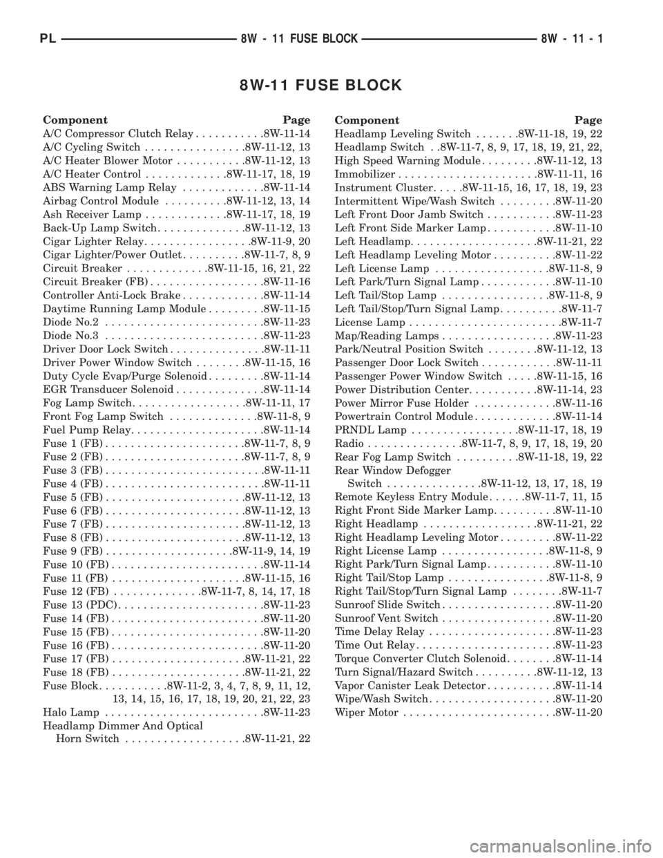
8W-11 FUSE BLOCK
Component Page
A/C Compressor Clutch Relay...........8W-11-14
A/C Cycling Switch................8W-11-12, 13
A/C Heater Blower Motor...........8W-11-12, 13
A/C Heater Control.............8W-11-17, 18, 19
ABS Warning Lamp Relay.............8W-11-14
Airbag Control Module..........8W-11-12, 13, 14
Ash Receiver Lamp.............8W-11-17, 18, 19
Back-Up Lamp Switch..............8W-11-12, 13
Cigar Lighter Relay.................8W-11-9, 20
Cigar Lighter/Power Outlet..........8W-11-7, 8, 9
Circuit Breaker.............8W-11-15, 16, 21, 22
Circuit Breaker (FB)..................8W-11-16
Controller Anti-Lock Brake.............8W-11-14
Daytime Running Lamp Module.........8W-11-15
Diode No.2.........................8W-11-23
Diode No.3.........................8W-11-23
Driver Door Lock Switch...............8W-11-11
Driver Power Window Switch........8W-11-15, 16
Duty Cycle Evap/Purge Solenoid.........8W-11-14
EGR Transducer Solenoid..............8W-11-14
Fog Lamp Switch..................8W-11-11,17
Front Fog Lamp Switch..............8W-11-8, 9
Fuel Pump Relay.....................8W-11-14
Fuse 1 (FB)......................8W-11-7, 8, 9
Fuse 2 (FB)......................8W-11-7, 8, 9
Fuse 3 (FB).........................8W-11-11
Fuse 4 (FB).........................8W-11-11
Fuse 5 (FB)......................8W-11-12, 13
Fuse 6 (FB)......................8W-11-12, 13
Fuse 7 (FB)......................8W-11-12, 13
Fuse 8 (FB)......................8W-11-12, 13
Fuse 9 (FB)....................8W-11-9, 14, 19
Fuse 10 (FB)........................8W-11-14
Fuse 11 (FB).....................8W-11-15, 16
Fuse 12 (FB)..............8W-11-7, 8, 14, 17, 18
Fuse 13 (PDC).......................8W-11-23
Fuse 14 (FB)........................8W-11-20
Fuse 15 (FB)........................8W-11-20
Fuse 16 (FB)........................8W-11-20
Fuse 17 (FB).....................8W-11-21, 22
Fuse 18 (FB).....................8W-11-21, 22
Fuse Block...........8W-11-2, 3, 4, 7, 8, 9, 11, 12,
13, 14, 15, 16, 17, 18, 19, 20, 21, 22, 23
Halo Lamp.........................8W-11-23
Headlamp Dimmer And Optical
Horn Switch...................8W-11-21, 22Component Page
Headlamp Leveling Switch.......8W-11-18, 19, 22
Headlamp Switch . .8W-11-7, 8, 9, 17, 18, 19, 21, 22,
High Speed Warning Module.........8W-11-12, 13
Immobilizer......................8W-11-11,16
Instrument Cluster.....8W-11-15, 16, 17, 18, 19, 23
Intermittent Wipe/Wash Switch.........8W-11-20
Left Front Door Jamb Switch...........8W-11-23
Left Front Side Marker Lamp...........8W-11-10
Left Headlamp....................8W-11-21, 22
Left Headlamp Leveling Motor..........8W-11-22
Left License Lamp..................8W-11-8, 9
Left Park/Turn Signal Lamp............8W-11-10
Left Tail/Stop Lamp.................8W-11-8, 9
Left Tail/Stop/Turn Signal Lamp..........8W-11-7
License Lamp........................8W-11-7
Map/Reading Lamps..................8W-11-23
Park/Neutral Position Switch........8W-11-12, 13
Passenger Door Lock Switch............8W-11-11
Passenger Power Window Switch.....8W-11-15, 16
Power Distribution Center...........8W-11-14, 23
Power Mirror Fuse Holder.............8W-11-16
Powertrain Control Module.............8W-11-14
PRNDL Lamp.................8W-11-17, 18, 19
Radio...............8W-11-7, 8, 9, 17, 18, 19, 20
Rear Fog Lamp Switch..........8W-11-18, 19, 22
Rear Window Defogger
Switch...............8W-11-12, 13, 17, 18, 19
Remote Keyless Entry Module......8W-11-7, 11, 15
Right Front Side Marker Lamp..........8W-11-10
Right Headlamp..................8W-11-21, 22
Right Headlamp Leveling Motor.........8W-11-22
Right License Lamp.................8W-11-8, 9
Right Park/Turn Signal Lamp...........8W-11-10
Right Tail/Stop Lamp................8W-11-8, 9
Right Tail/Stop/Turn Signal Lamp........8W-11-7
Sunroof Slide Switch..................8W-11-20
Sunroof Vent Switch..................8W-11-20
Time Delay Relay....................8W-11-23
Time Out Relay......................8W-11-23
Torque Converter Clutch Solenoid........8W-11-14
Turn Signal/Hazard Switch..........8W-11-12, 13
Vapor Canister Leak Detector...........8W-11-14
Wipe/Wash Switch....................8W-11-20
Wiper Motor........................8W-11-20
PL8W - 11 FUSE BLOCK 8W - 11 - 1