brake fluid DODGE NEON 1999 Service Repair Manual
[x] Cancel search | Manufacturer: DODGE, Model Year: 1999, Model line: NEON, Model: DODGE NEON 1999Pages: 1200, PDF Size: 35.29 MB
Page 4 of 1200
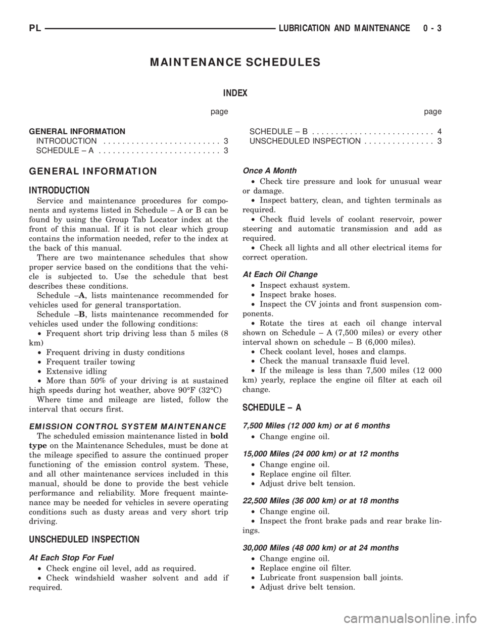
MAINTENANCE SCHEDULES
INDEX
page page
GENERAL INFORMATION
INTRODUCTION......................... 3
SCHEDULE ± A.......................... 3SCHEDULE ± B.......................... 4
UNSCHEDULED INSPECTION............... 3
GENERAL INFORMATION
INTRODUCTION
Service and maintenance procedures for compo-
nents and systems listed in Schedule ± A or B can be
found by using the Group Tab Locator index at the
front of this manual. If it is not clear which group
contains the information needed, refer to the index at
the back of this manual.
There are two maintenance schedules that show
proper service based on the conditions that the vehi-
cle is subjected to. Use the schedule that best
describes these conditions.
Schedule ±A, lists maintenance recommended for
vehicles used for general transportation.
Schedule ±B, lists maintenance recommended for
vehicles used under the following conditions:
²Frequent short trip driving less than 5 miles (8
km)
²Frequent driving in dusty conditions
²Frequent trailer towing
²Extensive idling
²More than 50% of your driving is at sustained
high speeds during hot weather, above 90ÉF (32ÉC)
Where time and mileage are listed, follow the
interval that occurs first.
EMISSION CONTROL SYSTEM MAINTENANCE
The scheduled emission maintenance listed inbold
typeon the Maintenance Schedules, must be done at
the mileage specified to assure the continued proper
functioning of the emission control system. These,
and all other maintenance services included in this
manual, should be done to provide the best vehicle
performance and reliability. More frequent mainte-
nance may be needed for vehicles in severe operating
conditions such as dusty areas and very short trip
driving.
UNSCHEDULED INSPECTION
At Each Stop For Fuel
²Check engine oil level, add as required.
²Check windshield washer solvent and add if
required.
Once A Month
²Check tire pressure and look for unusual wear
or damage.
²Inspect battery, clean, and tighten terminals as
required.
²Check fluid levels of coolant reservoir, power
steering and automatic transmission and add as
required.
²Check all lights and all other electrical items for
correct operation.
At Each Oil Change
²Inspect exhaust system.
²Inspect brake hoses.
²Inspect the CV joints and front suspension com-
ponents.
²Rotate the tires at each oil change interval
shown on Schedule ± A (7,500 miles) or every other
interval shown on schedule ± B (6,000 miles).
²Check coolant level, hoses and clamps.
²Check the manual transaxle fluid level.
²If the mileage is less than 7,500 miles (12 000
km) yearly, replace the engine oil filter at each oil
change.
SCHEDULE ± A
7,500 Miles (12 000 km) or at 6 months
²Change engine oil.
15,000 Miles (24 000 km) or at 12 months
²Change engine oil.
²Replace engine oil filter.
²Adjust drive belt tension.
22,500 Miles (36 000 km) or at 18 months
²Change engine oil.
²Inspect the front brake pads and rear brake lin-
ings.
30,000 Miles (48 000 km) or at 24 months
²Change engine oil.
²Replace engine oil filter.
²Lubricate front suspension ball joints.
²Adjust drive belt tension.
PLLUBRICATION AND MAINTENANCE 0 - 3
Page 5 of 1200
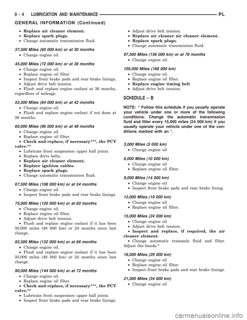
²Replace air cleaner element.
²Replace spark plugs.
²Change automatic transmission fluid.
37,500 Miles (60 000 km) or at 30 months
²Change engine oil.
45,000 Miles (72 000 km) or at 36 months
²Change engine oil.
²Replace engine oil filter.
²Inspect front brake pads and rear brake linings.
²Adjust drive belt tension.
²Flush and replace engine coolant at 36 months,
regardless of mileage.
52,500 Miles (84 000 km) or at 42 months
²Change engine oil.
²Flush and replace engine coolant if not done at
36 months.
60,000 Miles (96 000 km) or at 48 months
²Change engine oil.
²Replace engine oil filter.
²Check and replace, if necessary***, the PCV
valve.**
²Lubricate front suspension upper ball joints.
²Replace drive belts.
²Replace air cleaner element.
²Replace ignition cables.
²Replace spark plugs.
²Change automatic transmission fluid.
67,500 Miles (108 000 km) or at 54 months
²Change engine oil.
²Inspect front brake pads and rear brake linings.
75,000 Miles (120 000 km) or at 60 months
²Change engine oil.
²Replace engine oil filter.
²Adjust drive belt tension.
²Flush and replace engine coolant if it has been
30,000 miles (48 000 km) or 24 months since last
change.
82,500 Miles (132 000 km) or at 66 months
²Change engine oil.
²Flush and replace engine coolant if it has been
30,000 miles (48 000 km) or 24 months since last
change.
90,000 Miles (144 000 km) or at 72 months
²Change engine oil.
²Replace engine oil filter.
²Check and replace, if necessary***, the PCV
valve.**
²Lubricate front suspension upper ball joints.
²Inspect front brake pads and rear brake linings.²Adjust drive belt tension.
²Replace air cleaner air cleaner element.
²Replace spark plugs.
²Change automatic transmission fluid.
97,500 Miles (156 000 km) or at 78 months
²Change engine oil.
105,000 Miles (168 000 km)
²Change engine oil.
²Replace engine oil filter.
²Replace engine timing belt
²Adjust drive belt tension.
SCHEDULE ± B
NOTE: * Follow this schedule if you usually operate
your vehicle under one or more of the following
conditions. Change the automatic transmission
fluid and filter every 15,000 miles (24 000 km) if you
usually operate your vehicle under one of the con-
ditions marked with an *.
3,000 Miles (5 000 km)
²Change engine oil
6,000 Miles (10 000 km)
²Change engine oil
²Replace engine oil filter.
9,000 Miles (14 000 km)
²Change engine oil
²Inspect front brake pads and rear brake lining.
12,000 Miles (19 000 km)
²Change engine oil
²Replace engine oil filter.
15,000 Miles (24 000 km)
²Change engine oil
²Adjust drive belt tension.
²Inspect and replace, if required, the air
cleaner element.
²Change automatic transaxle fluid and filter.
Adjust the bands.*
18,000 Miles (29 000 km)
²Change engine oil
²Replace engine oil filter.
²Inspect front brake pads and rear brake linings.
21,000 Miles (34 000 km)
²Change engine oil
0 - 4 LUBRICATION AND MAINTENANCEPL
GENERAL INFORMATION (Continued)
Page 6 of 1200
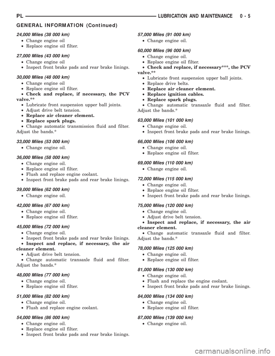
24,000 Miles (38 000 km)
²Change engine oil
²Replace engine oil filter.
27,000 Miles (43 000 km)
²Change engine oil
²Inspect front brake pads and rear brake linings.
30,000 Miles (48 000 km)
²Change engine oil
²Replace engine oil filter.
²Check and replace, if necessary, the PCV
valve.**
²Lubricate front suspension upper ball joints.
²Adjust drive belt tension.
²Replace air cleaner element.
²Replace spark plugs.
²Change automatic transmission fluid and filter.
Adjust the bands.*
33,000 Miles (53 000 km)
²Change engine oil.
36,000 Miles (58 000 km)
²Change engine oil.
²Replace engine oil filter.
²Flush and replace engine coolant.
²Inspect front brake pads and rear brake linings.
39,000 Miles (62 000 km)
²Change engine oil.
42,000 Miles (67 000 km)
²Change engine oil.
²Replace engine oil filter.
45,000 Miles (72 000 km)
²Change engine oil.
²Inspect front brake pads and rear brake linings.
²Inspect and replace, if necessary, the air
cleaner element.
²Adjust drive belt tension.
²Change automatic transaxle fluid and filter.
Adjust the bands.*
48,000 Miles (77 000 km)
²Change engine oil.
²Replace engine oil filter.
51,000 Miles (82 000 km)
²Change engine oil.
²Flush and replace engine coolant.
54,000 Miles (86 000 km)
²Change engine oil.
²Replace engine oil filter.
²Inspect front brake pads and rear brake linings.
57,000 Miles (91 000 km)
²Change engine oil.
60,000 Miles (96 000 km)
²Change engine oil.
²Replace engine oil filter.
²Check and replace, if necessary***, the PCV
valve.**
²Lubricate front suspension upper ball joints.
²Replace drive belts.
²Replace air cleaner element.
²Replace ignition cables.
²Replace spark plugs.
²Change automatic transaxle fluid and filter.
Adjust the bands.*
63,000 Miles (101 000 km)
²Change engine oil.
²Inspect front brake pads and rear brake linings.
66,000 Miles (106 000 km)
²Change engine oil.
²Replace engine oil filter.
69,000 Miles (110 000 km)
²Change engine oil.
72,000 Miles (115 000 km)
²Change engine oil.
²Replace engine oil filter.
²Inspect front brake pads and rear brake linings.
75,000 Miles (120 000 km)
²Change engine oil.
²Adjust drive belt tension.
²Inspect and replace, if necessary, the air
cleaner element.
²Change automatic transaxle fluid and filter.
Adjust the bands.*
78,000 Miles (125 000 km)
²Change engine oil.
²Replace engine oil filter.
81,000 Miles (130 000 km)
²Change engine oil.
²Flush and replace the engine coolant.
²Inspect front brake pads and rear brake linings.
84,000 Miles (134 000 km)
²Change engine oil.
²Replace engine oil filter.
87,000 Miles (139 000 km)
²Change engine oil.
PLLUBRICATION AND MAINTENANCE 0 - 5
GENERAL INFORMATION (Continued)
Page 7 of 1200
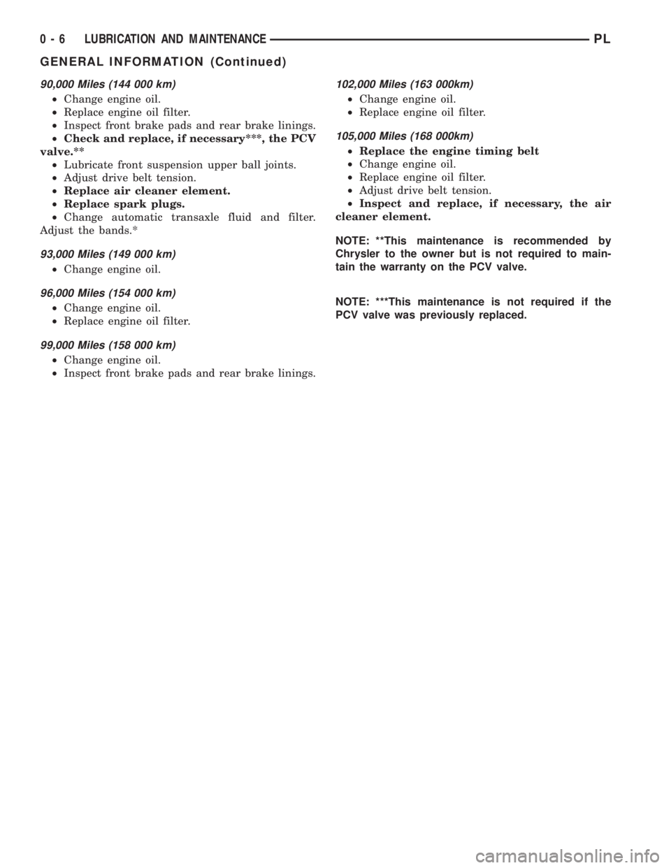
90,000 Miles (144 000 km)
²Change engine oil.
²Replace engine oil filter.
²Inspect front brake pads and rear brake linings.
²Check and replace, if necessary***, the PCV
valve.**
²Lubricate front suspension upper ball joints.
²Adjust drive belt tension.
²Replace air cleaner element.
²Replace spark plugs.
²Change automatic transaxle fluid and filter.
Adjust the bands.*
93,000 Miles (149 000 km)
²Change engine oil.
96,000 Miles (154 000 km)
²Change engine oil.
²Replace engine oil filter.
99,000 Miles (158 000 km)
²Change engine oil.
²Inspect front brake pads and rear brake linings.
102,000 Miles (163 000km)
²Change engine oil.
²Replace engine oil filter.
105,000 Miles (168 000km)
²Replace the engine timing belt
²Change engine oil.
²Replace engine oil filter.
²Adjust drive belt tension.
²Inspect and replace, if necessary, the air
cleaner element.
NOTE: **This maintenance is recommended by
Chrysler to the owner but is not required to main-
tain the warranty on the PCV valve.
NOTE: ***This maintenance is not required if the
PCV valve was previously replaced.
0 - 6 LUBRICATION AND MAINTENANCEPL
GENERAL INFORMATION (Continued)
Page 8 of 1200
JUMP STARTING, TOWING AND HOISTING
INDEX
page page
SERVICE PROCEDURES
HOISTING RECOMMENDATIONS............ 9JUMP STARTING PROCEDURE.............. 7
TOWING RECOMMENDATIONS.............. 8
SERVICE PROCEDURES
JUMP STARTING PROCEDURE
WARNING: REVIEW ALL SAFETY PRECAUTIONS
AND WARNINGS IN GROUP 8A, BATTERY/START-
ING/CHARGING SYSTEMS DIAGNOSTICS. DO NOT
JUMP START A FROZEN BATTERY, PERSONAL
INJURY CAN RESULT. DO NOT JUMP START WHEN
MAINTENANCE FREE BATTERY INDICATOR DOT IS
YELLOW OR BRIGHT COLOR. DO NOT JUMP
START A VEHICLE WHEN THE BATTERY FLUID IS
BELOW THE TOP OF LEAD PLATES. DO NOT
ALLOW JUMPER CABLE CLAMPS TO TOUCH
EACH OTHER WHEN CONNECTED TO A BOOSTER
SOURCE. DO NOT USE OPEN FLAME NEAR BAT-
TERY. REMOVE METALLIC JEWELRY WORN ON
HANDS OR WRISTS TO AVOID INJURY BY ACCI-
DENTAL ARCING OF BATTERY CURRENT. WHEN
USING A HIGH OUTPUT BOOSTING DEVICE, DO
NOT ALLOW BATTERY VOLTAGE TO EXCEED 16
VOLTS. REFER TO INSTRUCTIONS PROVIDED
WITH DEVICE BEING USED.
CAUTION: When using another vehicle as a
booster, do not allow vehicles to touch. Electrical
systems can be damaged on either vehicle.
TO JUMP START A DISABLED VEHICLE:
(1) Raise hood on disabled vehicle and visually
inspect engine compartment for:
²Battery cable clamp condition, clean if necessary.
²Frozen battery.
²Yellow or bright color test indicator, if equipped.
²Low battery fluid level.
²Generator drive belt condition and tension.
²Fuel fumes or leakage, correct if necessary.
CAUTION: If the cause of starting problem on dis-
abled vehicle is severe, damage to booster vehicle
charging system can result.
(2) When using another vehicle as a booster
source, park the booster vehicle within cable reach.
Turn off all accessories, set the parking brake, placethe automatic transmission in PARK or the manual
transmission in NEUTRAL and turn the ignition
OFF.
(3) On disabled vehicle, place gear selector in park
or neutral and set park brake. Turn off all accesso-
ries.
(4) Connect jumper cables to booster battery. RED
clamp to positive terminal (+). BLACK clamp to neg-
ative terminal (-). DO NOT allow clamps at opposite
end of cables to touch, electrical arc will result.
Review all warnings in this procedure.
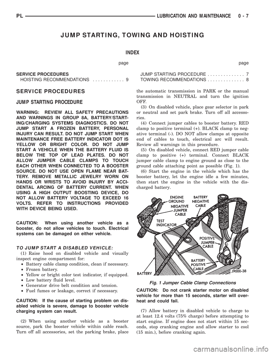
(5) On disabled vehicle, connect RED jumper cable
clamp to positive (+) terminal. Connect BLACK
jumper cable clamp to engine ground as close to the
ground cable attaching point as possible (Fig. 1).
(6) Start the engine in the vehicle which has the
booster battery, let the engine idle a few minutes,
then start the engine in the vehicle with the dis-
charged battery.
CAUTION: Do not crank starter motor on disabled
vehicle for more than 15 seconds, starter will over-
heat and could fail.
(7) Allow battery in disabled vehicle to charge to
at least 12.4 volts (75% charge) before attempting to
start engine. If engine does not start within 15 sec-
onds, stop cranking engine and allow starter to cool
(15 min.), before cranking again.
Fig. 1 Jumper Cable Clamp Connections
PLLUBRICATION AND MAINTENANCE 0 - 7
Page 71 of 1200
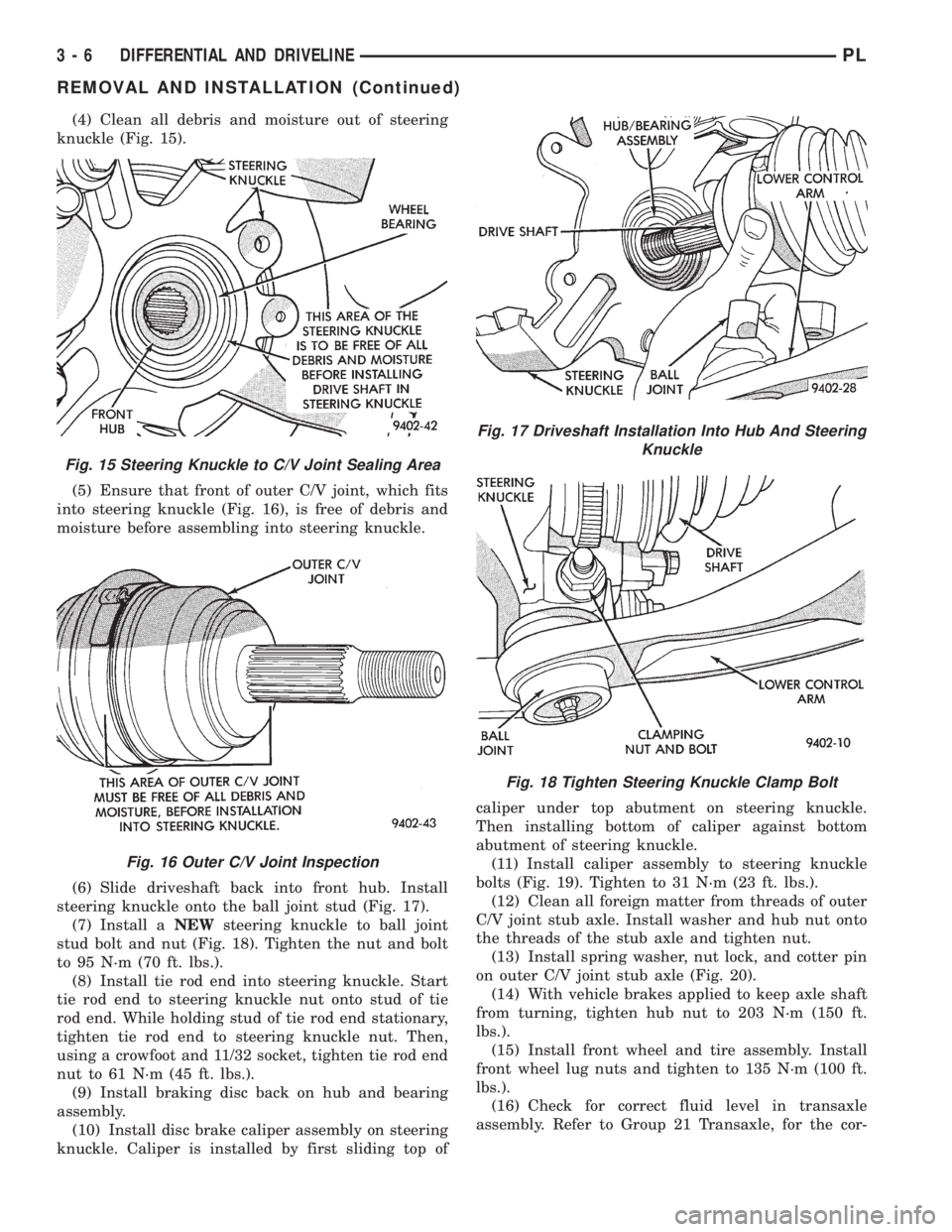
(4) Clean all debris and moisture out of steering
knuckle (Fig. 15).
(5) Ensure that front of outer C/V joint, which fits
into steering knuckle (Fig. 16), is free of debris and
moisture before assembling into steering knuckle.
(6) Slide driveshaft back into front hub. Install
steering knuckle onto the ball joint stud (Fig. 17).
(7) Install aNEWsteering knuckle to ball joint
stud bolt and nut (Fig. 18). Tighten the nut and bolt
to 95 N´m (70 ft. lbs.).
(8) Install tie rod end into steering knuckle. Start
tie rod end to steering knuckle nut onto stud of tie
rod end. While holding stud of tie rod end stationary,
tighten tie rod end to steering knuckle nut. Then,
using a crowfoot and 11/32 socket, tighten tie rod end
nut to 61 N´m (45 ft. lbs.).
(9) Install braking disc back on hub and bearing
assembly.
(10) Install disc brake caliper assembly on steering
knuckle. Caliper is installed by first sliding top ofcaliper under top abutment on steering knuckle.
Then installing bottom of caliper against bottom
abutment of steering knuckle.
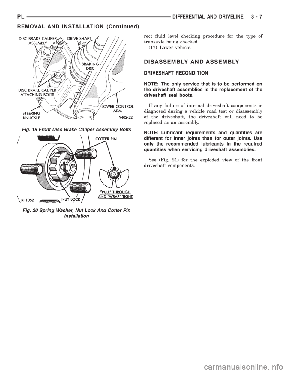
(11) Install caliper assembly to steering knuckle
bolts (Fig. 19). Tighten to 31 N´m (23 ft. lbs.).
(12) Clean all foreign matter from threads of outer
C/V joint stub axle. Install washer and hub nut onto
the threads of the stub axle and tighten nut.
(13) Install spring washer, nut lock, and cotter pin
on outer C/V joint stub axle (Fig. 20).
(14) With vehicle brakes applied to keep axle shaft
from turning, tighten hub nut to 203 N´m (150 ft.
lbs.).
(15) Install front wheel and tire assembly. Install
front wheel lug nuts and tighten to 135 N´m (100 ft.
lbs.).
(16) Check for correct fluid level in transaxle
assembly. Refer to Group 21 Transaxle, for the cor-
Fig. 15 Steering Knuckle to C/V Joint Sealing Area
Fig. 16 Outer C/V Joint Inspection
Fig. 17 Driveshaft Installation Into Hub And Steering
Knuckle
Fig. 18 Tighten Steering Knuckle Clamp Bolt
3 - 6 DIFFERENTIAL AND DRIVELINEPL
REMOVAL AND INSTALLATION (Continued)
Page 72 of 1200
rect fluid level checking procedure for the type of
transaxle being checked.
(17) Lower vehicle.
DISASSEMBLY AND ASSEMBLY
DRIVESHAFT RECONDITION
NOTE: The only service that is to be performed on
the driveshaft assemblies is the replacement of the
driveshaft seal boots.
If any failure of internal driveshaft components is
diagnosed during a vehicle road test or disassembly
of the driveshaft, the driveshaft will need to be
replaced as an assembly.
NOTE: Lubricant requirements and quantities are
different for inner joints than for outer joints. Use
only the recommended lubricants in the required
quantities when servicing driveshaft assemblies.
See (Fig. 21) for the exploded view of the front
driveshaft components.
Fig. 19 Front Disc Brake Caliper Assembly Bolts
Fig. 20 Spring Washer, Nut Lock And Cotter Pin
Installation
PLDIFFERENTIAL AND DRIVELINE 3 - 7
REMOVAL AND INSTALLATION (Continued)
Page 82 of 1200
BRAKES
CONTENTS
page page
ANTILOCK BRAKE SYSTEM±TEVES MARK 20 . 69
BASE BRAKE SYSTEM..................... 2GENERAL INFORMATION................... 1
GENERAL INFORMATION
INDEX
page
GENERAL INFORMATION
BASE BRAKE SYSTEM DESCRIPTION........ 1
GENERAL INFORMATION
BASE BRAKE SYSTEM DESCRIPTION
Typical brake equipment consists of:
²Double pin floating caliper disc front brakes.
²Rear automatic adjusting drum brakes.
²Brake Fluid Level Switch.
²Master cylinder.
²Vacuum power booster.
²Double pin floating caliper rear disc brakes are
available on some models.
²Hand operated auto adjust park brake lever.
²Front disc brake pads are semi-metallic.
Vehicles equipped with the optional antilock brake
system (ABS) use a system designated Mark 20 and
is supplied by Teves. This system shares the base
brake hardware with vehicles not equipped withABS. A vehicle equipped with ABS does however use
a different vacuum booster, master cylinder and
brake tubes. Also included in the ABS system is an
integrated control unit (ICU), four wheel speed sen-
sors, and an electronic controller referred to as the
controller antilock brakes (CAB). These components
will be described in detail in the Teves Mark 20 ABS
brake section in this group of the service manual.
The hydraulic brake system is diagonally split on
both the Non-ABS and ABS braking system. With the
left front and right rear brakes on one hydraulic sys-
tem and the right front and left rear on the other.
The master cylinder is anodized, lightweight alu-
minum. On vehicles equipped with front disc brakes
and rear drum brakes, the master cylinder bore is
21.0 mm. On vehicles equipped with four wheel disc
brakes, the master cylinder bore is 22.2 mm.
PLBRAKES 5 - 1
Page 83 of 1200
BASE BRAKE SYSTEM
INDEX
page page
DESCRIPTION AND OPERATION
CHASSIS TUBES AND HOSES.............. 6
FRONT DISC BRAKES..................... 2
MASTER CYLINDER...................... 6
PARKING BRAKES........................ 4
PROPORTIONING VALVES................. 5
REAR DISC BRAKES...................... 4
REAR DRUM BRAKES..................... 4
REAR WHEEL HUB/BEARING............... 8
RED BRAKE WARNING LAMP............... 7
STOP LAMP SWITCH...................... 8
VACUUM BOOSTER...................... 6
DIAGNOSIS AND TESTING
BRAKE FLUID CONTAMINATION............ 19
BRAKE SYSTEM BASIC DIAGNOSIS GUIDE.... 9
BRAKE SYSTEM DIAGNOSIS CHARTS....... 10
DRUM BRAKE AUTOMATIC ADJUSTER....... 14
PROPORTIONING VALVES................ 16
RED BRAKE WARNING LAMP TEST......... 19
ROTOR THICKNESS AND RUNOUT.......... 14
STOP LAMP SWITCH TEST PROCEDURE..... 19
SERVICE PROCEDURES
BRAKE BLEEDING....................... 20
BRAKE DRUM MACHINING................ 23
BRAKE FLUID LEVEL CHECK.............. 19
BRAKE ROTOR MACHINING............... 22
BRAKE TUBE REPAIR.................... 25
MASTER CYLINDER BLEEDING............ 21
PARK BRAKE LEVER AUTO ADJUSTER
MECHANISM.......................... 23
REMOVAL AND INSTALLATION
CHASSIS TUBES AND HOSES.............. 47
FRONT DISC BRAKE CALIPER............. 26
FRONT DISC BRAKE SHOES.............. 28
MASTER CYLINDER..................... 41
PARK BRAKE CABLES.................... 50
PARK BRAKE LEVER ASSEMBLY........... 48PARK BRAKE LEVER OUTPUT CABLE....... 49
PARK BRAKE SHOES WITH REAR DISC
BRAKES............................. 55
PROPORTIONING VALVE (BASE BRAKES).... 47
REAR BRAKE DRUM..................... 34
REAR BRAKE SHOE SUPPORT PLATE....... 37
REAR BRAKE SHOES.................... 35
REAR BRAKE WHEEL CYLINDER........... 38
REAR DISC BRAKE CALIPER.............. 30
REAR DISC BRAKE SHOES................ 32
REAR HUB/BEARING..................... 39
STOP LAMP SWITCH..................... 57
VACUUM BOOSTER..................... 44
WHEEL AND TIRE ASSEMBLY.............. 26
DISASSEMBLY AND ASSEMBLY
BRAKE FLUID LEVEL SWITCH............. 58
BRAKE FLUID RESERVOIR................ 57
FRONT AND REAR DISC BRAKE CALIPER.... 58
WHEEL CYLINDER (REAR DRUM BRAKE).... 63
CLEANING AND INSPECTION
CHASSIS TUBES AND HOSES.............. 65
FRONT DISC BRAKES.................... 63
REAR DISC BRAKES..................... 64
REAR DRUM BRAKE WHEEL CYLINDER...... 65
REAR DRUM BRAKES.................... 64
REAR WHEEL HUB AND BEARING ASSEMBLY . 65
ADJUSTMENTS
PARK BRAKE ADJUSTMENT............... 66
REAR DRUM BRAKE SHOE ADJUSTMENT.... 65
STOP LAMP SWITCH..................... 65
SPECIFICATIONS
BRAKE ACTUATION SYSTEM.............. 67
BRAKE FASTENER TORQUE SPECIFICATIONS . 67
BRAKE FLUID.......................... 67
SPECIAL TOOLS
BASE BRAKE SYSTEM................... 68
DESCRIPTION AND OPERATION
FRONT DISC BRAKES
The front disc brakes (Fig. 1) and (Fig. 2) consists
of the following components:
²The driving hub
²Braking disc (rotor)
²Caliper assembly - single piston, floating type
²Brake shoes and linings
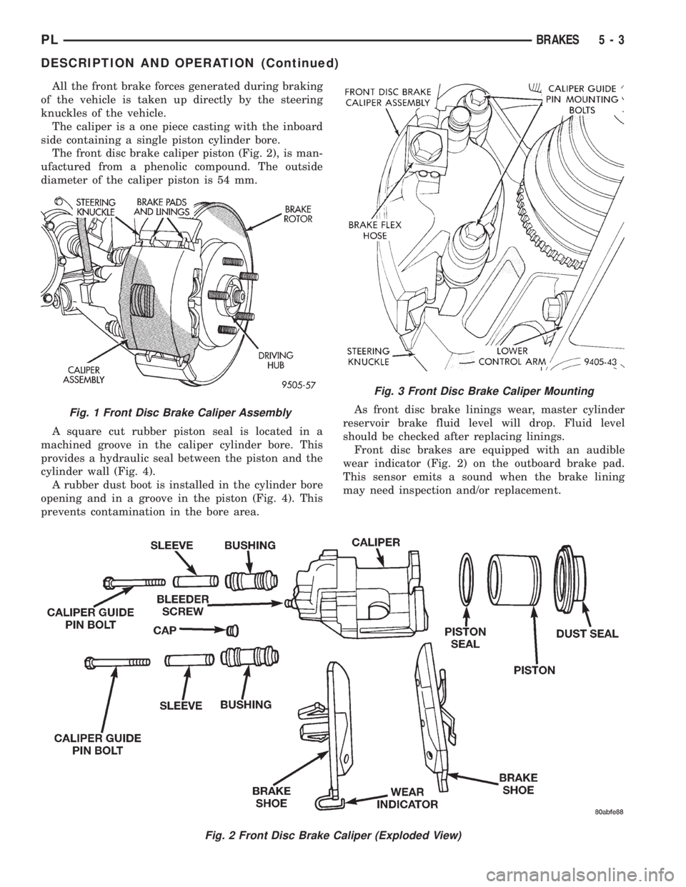
The double pin calipers are mounted directly to the
steering knuckles and use no adapter. The caliper ismounted to the steering knuckle using bushings,
sleeves and 2 guide pin bolts which thread directly
into bosses on the steering knuckle (Fig. 2) and (Fig.
3).
Two machined abutments on the steering knuckle
position the caliper. The guide pin bolts, sleeves and
bushings control the side to side movement of the
caliper. The piston seal is designed to pull the piston
back into the bore of the caliper when the brake
pedal is released. This maintains the proper brake
shoe to rotor clearance (Fig. 4).
5 - 2 BRAKESPL
Page 84 of 1200
All the front brake forces generated during braking
of the vehicle is taken up directly by the steering
knuckles of the vehicle.
The caliper is a one piece casting with the inboard
side containing a single piston cylinder bore.
The front disc brake caliper piston (Fig. 2), is man-
ufactured from a phenolic compound. The outside
diameter of the caliper piston is 54 mm.
A square cut rubber piston seal is located in a
machined groove in the caliper cylinder bore. This
provides a hydraulic seal between the piston and the
cylinder wall (Fig. 4).
A rubber dust boot is installed in the cylinder bore
opening and in a groove in the piston (Fig. 4). This
prevents contamination in the bore area.As front disc brake linings wear, master cylinder
reservoir brake fluid level will drop. Fluid level
should be checked after replacing linings.
Front disc brakes are equipped with an audible
wear indicator (Fig. 2) on the outboard brake pad.
This sensor emits a sound when the brake lining
may need inspection and/or replacement.
Fig. 1 Front Disc Brake Caliper Assembly
Fig. 2 Front Disc Brake Caliper (Exploded View)
Fig. 3 Front Disc Brake Caliper Mounting
PLBRAKES 5 - 3
DESCRIPTION AND OPERATION (Continued)