tire type DODGE NEON 1999 Service Owner's Guide
[x] Cancel search | Manufacturer: DODGE, Model Year: 1999, Model line: NEON, Model: DODGE NEON 1999Pages: 1200, PDF Size: 35.29 MB
Page 906 of 1200
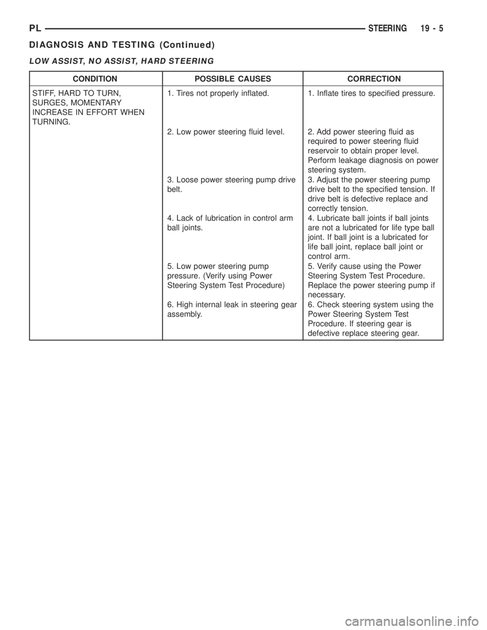
LOW ASSIST, NO ASSIST, HARD STEERING
CONDITION POSSIBLE CAUSES CORRECTION
STIFF, HARD TO TURN,
SURGES, MOMENTARY
INCREASE IN EFFORT WHEN
TURNING.1. Tires not properly inflated. 1. Inflate tires to specified pressure.
2. Low power steering fluid level. 2. Add power steering fluid as
required to power steering fluid
reservoir to obtain proper level.
Perform leakage diagnosis on power
steering system.
3. Loose power steering pump drive
belt.3. Adjust the power steering pump
drive belt to the specified tension. If
drive belt is defective replace and
correctly tension.
4. Lack of lubrication in control arm
ball joints.4. Lubricate ball joints if ball joints
are not a lubricated for life type ball
joint. If ball joint is a lubricated for
life ball joint, replace ball joint or
control arm.
5. Low power steering pump
pressure. (Verify using Power
Steering System Test Procedure)5. Verify cause using the Power
Steering System Test Procedure.
Replace the power steering pump if
necessary.
6. High internal leak in steering gear
assembly.6. Check steering system using the
Power Steering System Test
Procedure. If steering gear is
defective replace steering gear.
PLSTEERING 19 - 5
DIAGNOSIS AND TESTING (Continued)
Page 907 of 1200
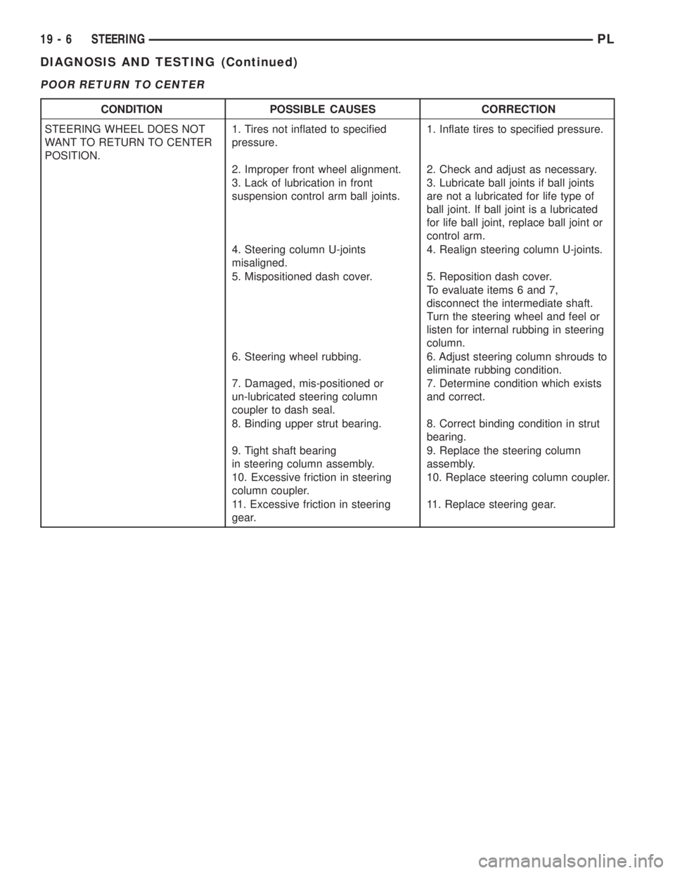
POOR RETURN TO CENTER
CONDITION POSSIBLE CAUSES CORRECTION
STEERING WHEEL DOES NOT
WANT TO RETURN TO CENTER
POSITION.1. Tires not inflated to specified
pressure.1. Inflate tires to specified pressure.
2. Improper front wheel alignment. 2. Check and adjust as necessary.
3. Lack of lubrication in front
suspension control arm ball joints.3. Lubricate ball joints if ball joints
are not a lubricated for life type of
ball joint. If ball joint is a lubricated
for life ball joint, replace ball joint or
control arm.
4. Steering column U-joints
misaligned.4. Realign steering column U-joints.
5. Mispositioned dash cover. 5. Reposition dash cover.
To evaluate items 6 and 7,
disconnect the intermediate shaft.
Turn the steering wheel and feel or
listen for internal rubbing in steering
column.
6. Steering wheel rubbing. 6. Adjust steering column shrouds to
eliminate rubbing condition.
7. Damaged, mis-positioned or
un-lubricated steering column
coupler to dash seal.7. Determine condition which exists
and correct.
8. Binding upper strut bearing. 8. Correct binding condition in strut
bearing.
9. Tight shaft bearing
in steering column assembly.9. Replace the steering column
assembly.
10. Excessive friction in steering
column coupler.10. Replace steering column coupler.
11. Excessive friction in steering
gear.11. Replace steering gear.
19 - 6 STEERINGPL
DIAGNOSIS AND TESTING (Continued)
Page 913 of 1200
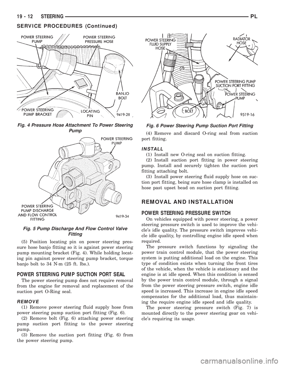
(5) Position locating pin on power steering pres-
sure hose banjo fitting so it is against power steering
pump mounting bracket (Fig. 4). While holding locat-
ing pin against power steering pump bracket, torque
banjo bolt to 34 N´m (25 ft. lbs.).
POWER STEERING PUMP SUCTION PORT SEAL
The power steering pump does not require removal
from the engine for removal and replacement of the
suction port O-Ring seal.
REMOVE
(1) Remove power steering fluid supply hose from
power steering pump suction port fitting (Fig. 6).
(2) Remove bolt (Fig. 6) attaching power steering
pump suction port fitting to the power steering
pump.
(3) Remove the suction port fitting (Fig. 6) from
the power steering pump.(4) Remove and discard O-ring seal from suction
port fitting.
INSTALL
(1) Install new O-ring seal on suction fitting.
(2) Install suction port fitting in power steering
pump. Install and securely tighten the suction port
fitting attaching bolt.
(3) Install power steering fluid supply hose on suc-
tion port fitting, being sure hose clamp is installed on
hose past upset bead on suction port fitting.
REMOVAL AND INSTALLATION
POWER STEERING PRESSURE SWITCH
On vehicles equipped with power steering, a power
steering pressure switch is used to improve the vehi-
cle's idle quality. The pressure switch improves vehi-
cle idle quality, by controlling engine idle speed when
required.
The pressure switch functions by signaling the
power train control module, that the power steering
system is putting additional load on the engine. This
type of condition exists when turning the front tires
of the vehicle, when the vehicle is stationary and the
engine is at idle speed. When this condition is sensed
by the power train control module, through a signal
from the power steering pressure switch, engine idle
speed is increased. This increase in engine idle speed
compensates for the additional load, thus maintain-
ing the require engine idle speed and idle quality.
The power steering pressure switch (Fig. 7) is
mounted directly to the power steering gear on vehi-
cle's requiring its usage.
Fig. 4 Pressure Hose Attachment To Power Steering
Pump
Fig. 5 Pump Discharge And Flow Control Valve
Fitting
Fig. 6 Power Steering Pump Suction Port Fitting
19 - 12 STEERINGPL
SERVICE PROCEDURES (Continued)
Page 929 of 1200
pressures are not the same against either stop, the
steering gear is leaking internally and must be
replaced.
REMOVAL AND INSTALLATION
MANUAL AND POWER STEERING GEAR
The removal and replacement procedure for both
the manual and power steering gears is the same.
The only additional steps of the procedure for the
power steering gear, is the removal and replacement
of the power steering fluid lines at the steering gear.
REMOVE
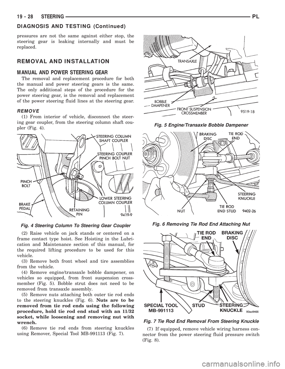
(1) From interior of vehicle, disconnect the steer-
ing gear coupler, from the steering column shaft cou-
pler (Fig. 4).
(2) Raise vehicle on jack stands or centered on a
frame contact type hoist. See Hoisting in the Lubri-
cation and Maintenance section of this manual, for
the required lifting procedure to be used for this
vehicle.
(3) Remove both front wheel and tire assemblies
from the vehicle.
(4) Remove engine/transaxle bobble dampener, on
vehicles so equipped, from front suspension cross-
member (Fig. 5). Bobble strut does not need to be
removed from transaxle assembly.
(5) Remove nuts attaching both outer tie rod ends
to the steering knuckles (Fig. 6).Nuts are to be
removed from tie rod ends using the following
procedure, hold tie rod end stud with an 11/32
socket, while loosening and removing nut with
wrench.
(6) Remove tie rod ends from steering knuckles
using Remover, Special Tool MB-991113 (Fig. 7).(7) If equipped, remove vehicle wiring harness con-
nector from the power steering fluid pressure switch
(Fig. 8).
Fig. 4 Steering Column To Steering Gear Coupler
Fig. 5 Engine/Transaxle Bobble Dampener
Fig. 6 Removing Tie Rod End Attaching Nut
Fig. 7 Tie Rod End Removal From Steering Knuckle
19 - 28 STEERINGPL
DIAGNOSIS AND TESTING (Continued)
Page 1068 of 1200
TIRES AND WHEELS
CONTENTS
page page
TIRES.................................. 1WHEELS................................ 8
TIRES
INDEX
page page
DESCRIPTION AND OPERATION
RADIAL-PLY TIRES....................... 2
REPLACEMENT TIRES.................... 3
SPARE TIRE±TEMPORARY................. 2
TIRE INFLATION PRESSURES.............. 2
TIRE INFORMATION...................... 1
TIRE PRESSURE FOR HIGH SPEED
OPERATION........................... 3
DIAGNOSIS AND TESTING
LEAD CORRECTION CHART................ 4
PRESSURE GAUGES..................... 3TIRE NOISE OR VIBRATION................ 4
TIRE WEAR PATTERNS.................... 3
TREAD WEAR INDICATORS................ 3
SERVICE PROCEDURES
REPAIRING TIRE LEAKS................... 4
TIRE AND WHEEL MATCH MOUNTING........ 6
TIRE AND WHEEL ROTATION............... 4
CLEANING AND INSPECTION
CLEANING TIRES........................ 7
SPECIFICATIONS
TIRE SPECIFICATIONS.................... 7
DESCRIPTION AND OPERATION
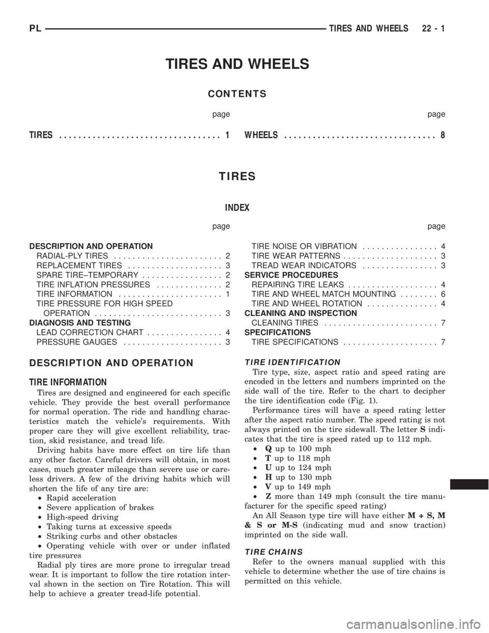
TIRE INFORMATION
Tires are designed and engineered for each specific
vehicle. They provide the best overall performance
for normal operation. The ride and handling charac-
teristics match the vehicle's requirements. With
proper care they will give excellent reliability, trac-
tion, skid resistance, and tread life.
Driving habits have more effect on tire life than
any other factor. Careful drivers will obtain, in most
cases, much greater mileage than severe use or care-
less drivers. A few of the driving habits which will
shorten the life of any tire are:
²Rapid acceleration
²Severe application of brakes
²High-speed driving
²Taking turns at excessive speeds
²Striking curbs and other obstacles
²Operating vehicle with over or under inflated
tire pressures
Radial ply tires are more prone to irregular tread
wear. It is important to follow the tire rotation inter-
val shown in the section on Tire Rotation. This will
help to achieve a greater tread-life potential.
TIRE IDENTIFICATION
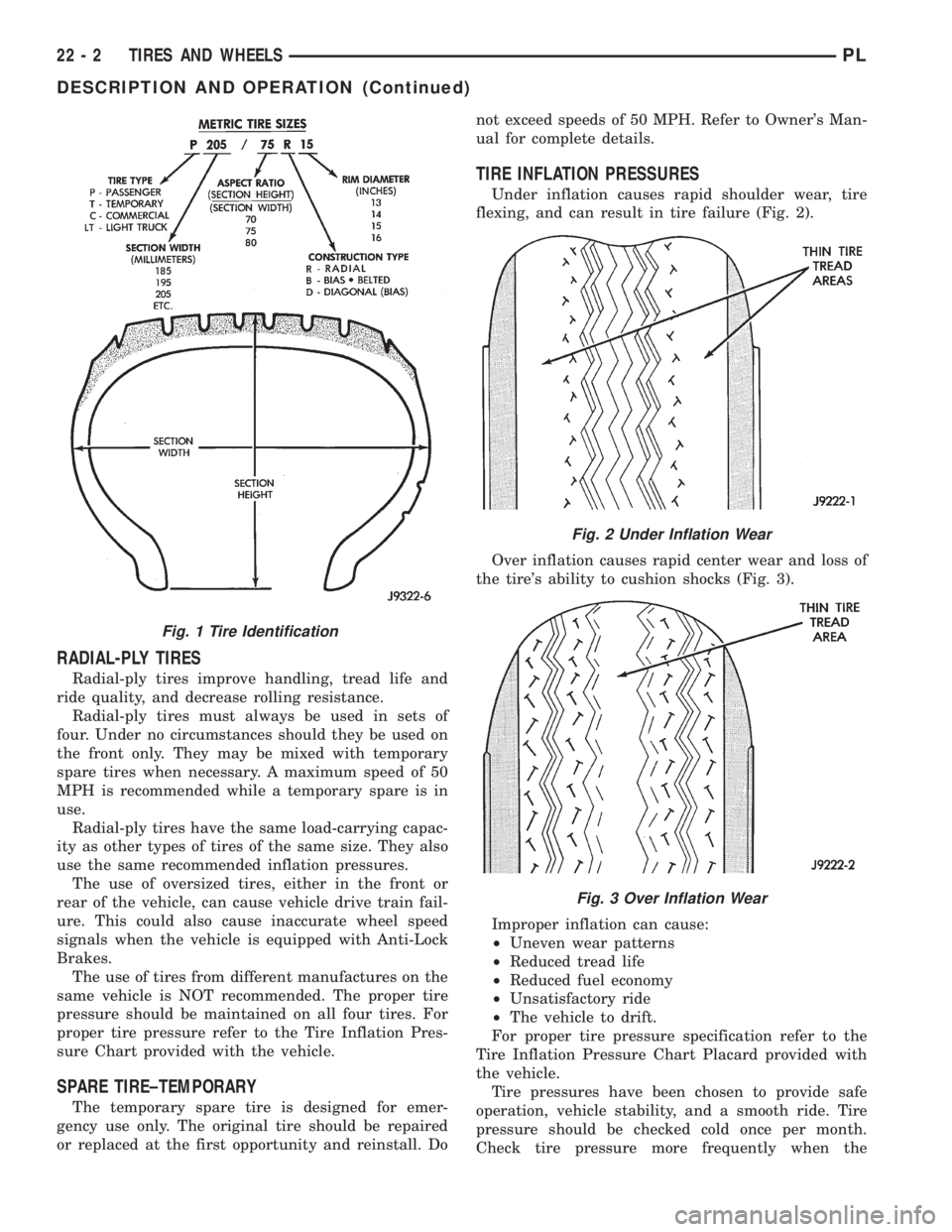
Tire type, size, aspect ratio and speed rating are
encoded in the letters and numbers imprinted on the
side wall of the tire. Refer to the chart to decipher
the tire identification code (Fig. 1).
Performance tires will have a speed rating letter
after the aspect ratio number. The speed rating is not
always printed on the tire sidewall. The letterSindi-
cates that the tire is speed rated up to 112 mph.
²Qup to 100 mph
²Tup to 118 mph
²Uup to 124 mph
²Hup to 130 mph
²Vup to 149 mph
²Zmore than 149 mph (consult the tire manu-
facturer for the specific speed rating)
An All Season type tire will have eitherM+S,M
&SorM-S(indicating mud and snow traction)
imprinted on the side wall.
TIRE CHAINS
Refer to the owners manual supplied with this
vehicle to determine whether the use of tire chains is
permitted on this vehicle.
PLTIRES AND WHEELS 22 - 1
Page 1069 of 1200
RADIAL-PLY TIRES
Radial-ply tires improve handling, tread life and
ride quality, and decrease rolling resistance.
Radial-ply tires must always be used in sets of
four. Under no circumstances should they be used on
the front only. They may be mixed with temporary
spare tires when necessary. A maximum speed of 50
MPH is recommended while a temporary spare is in
use.
Radial-ply tires have the same load-carrying capac-
ity as other types of tires of the same size. They also
use the same recommended inflation pressures.
The use of oversized tires, either in the front or
rear of the vehicle, can cause vehicle drive train fail-
ure. This could also cause inaccurate wheel speed
signals when the vehicle is equipped with Anti-Lock
Brakes.
The use of tires from different manufactures on the
same vehicle is NOT recommended. The proper tire
pressure should be maintained on all four tires. For
proper tire pressure refer to the Tire Inflation Pres-
sure Chart provided with the vehicle.
SPARE TIRE±TEMPORARY
The temporary spare tire is designed for emer-
gency use only. The original tire should be repaired
or replaced at the first opportunity and reinstall. Donot exceed speeds of 50 MPH. Refer to Owner's Man-
ual for complete details.
TIRE INFLATION PRESSURES
Under inflation causes rapid shoulder wear, tire
flexing, and can result in tire failure (Fig. 2).
Over inflation causes rapid center wear and loss of
the tire's ability to cushion shocks (Fig. 3).
Improper inflation can cause:
²Uneven wear patterns
²Reduced tread life
²Reduced fuel economy
²Unsatisfactory ride
²The vehicle to drift.
For proper tire pressure specification refer to the
Tire Inflation Pressure Chart Placard provided with
the vehicle.
Tire pressures have been chosen to provide safe
operation, vehicle stability, and a smooth ride. Tire
pressure should be checked cold once per month.
Check tire pressure more frequently when the
Fig. 1 Tire Identification
Fig. 2 Under Inflation Wear
Fig. 3 Over Inflation Wear
22 - 2 TIRES AND WHEELSPL
DESCRIPTION AND OPERATION (Continued)
Page 1075 of 1200
WHEELS
INDEX
page page
DESCRIPTION AND OPERATION
WHEEL COVER (LOCK-ON)................. 8
WHEEL INFORMATION.................... 8
DIAGNOSIS AND TESTING
TIRE AND WHEEL RUNOUT................ 9
WHEEL INSPECTION...................... 9
SERVICE PROCEDURES
TIRE AND WHEEL BALANCE............... 10REMOVAL AND INSTALLATION
WHEEL AND TIRE....................... 12
WHEEL COVER (LOCK-ON)................ 12
WHEEL COVER RETAINING NUT........... 13
SPECIFICATIONS
WHEEL SPECIFICATIONS................. 14
DESCRIPTION AND OPERATION
WHEEL INFORMATION
Original equipment wheels are designed for proper
operation at all loads up to the specified maximum
vehicle capacity.
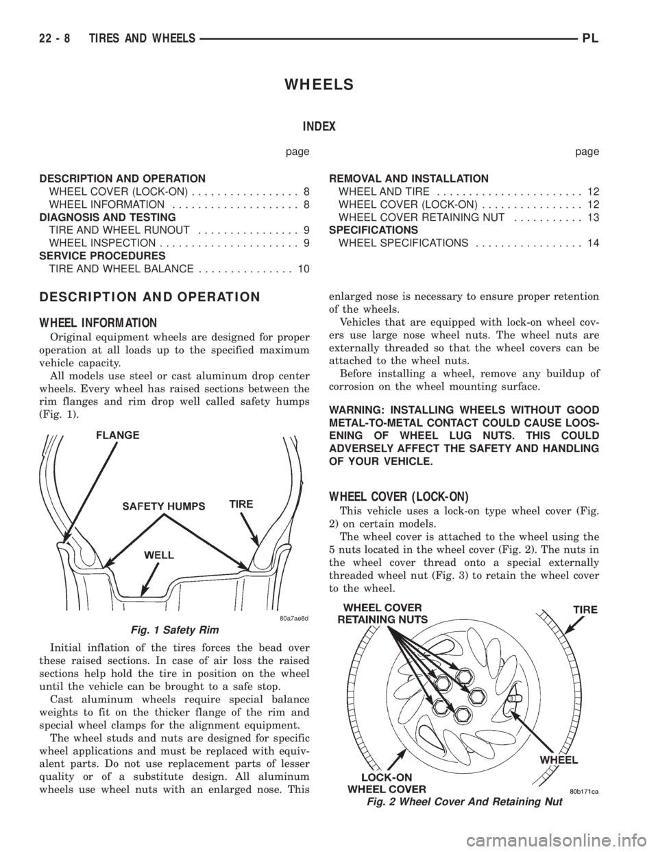
All models use steel or cast aluminum drop center
wheels. Every wheel has raised sections between the
rim flanges and rim drop well called safety humps
(Fig. 1).
Initial inflation of the tires forces the bead over
these raised sections. In case of air loss the raised
sections help hold the tire in position on the wheel
until the vehicle can be brought to a safe stop.
Cast aluminum wheels require special balance
weights to fit on the thicker flange of the rim and
special wheel clamps for the alignment equipment.
The wheel studs and nuts are designed for specific
wheel applications and must be replaced with equiv-
alent parts. Do not use replacement parts of lesser
quality or of a substitute design. All aluminum
wheels use wheel nuts with an enlarged nose. Thisenlarged nose is necessary to ensure proper retention
of the wheels.
Vehicles that are equipped with lock-on wheel cov-
ers use large nose wheel nuts. The wheel nuts are
externally threaded so that the wheel covers can be
attached to the wheel nuts.
Before installing a wheel, remove any buildup of
corrosion on the wheel mounting surface.
WARNING: INSTALLING WHEELS WITHOUT GOOD
METAL-TO-METAL CONTACT COULD CAUSE LOOS-
ENING OF WHEEL LUG NUTS. THIS COULD
ADVERSELY AFFECT THE SAFETY AND HANDLING
OF YOUR VEHICLE.
WHEEL COVER (LOCK-ON)
This vehicle uses a lock-on type wheel cover (Fig.
2) on certain models.
The wheel cover is attached to the wheel using the
5 nuts located in the wheel cover (Fig. 2). The nuts in
the wheel cover thread onto a special externally
threaded wheel nut (Fig. 3) to retain the wheel cover
to the wheel.
Fig. 1 Safety Rim
Fig. 2 Wheel Cover And Retaining Nut
22 - 8 TIRES AND WHEELSPL