ad blue DODGE NEON 1999 Service Repair Manual
[x] Cancel search | Manufacturer: DODGE, Model Year: 1999, Model line: NEON, Model: DODGE NEON 1999Pages: 1200, PDF Size: 35.29 MB
Page 397 of 1200
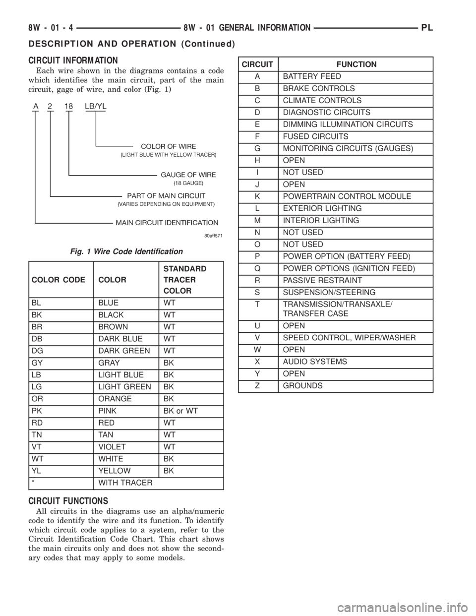
CIRCUIT INFORMATION
Each wire shown in the diagrams contains a code
which identifies the main circuit, part of the main
circuit, gage of wire, and color (Fig. 1)
CIRCUIT FUNCTIONS
All circuits in the diagrams use an alpha/numeric
code to identify the wire and its function. To identify
which circuit code applies to a system, refer to the
Circuit Identification Code Chart. This chart shows
the main circuits only and does not show the second-
ary codes that may apply to some models.
Fig. 1 Wire Code Identification
COLOR CODE COLORSTANDARD
TRACER
COLOR
BL BLUE WT
BK BLACK WT
BR BROWN WT
DB DARK BLUE WT
DG DARK GREEN WT
GY GRAY BK
LB LIGHT BLUE BK
LG LIGHT GREEN BK
OR ORANGE BK
PK PINK BK or WT
RD RED WT
TN TAN WT
VT VIOLET WT
WT WHITE BK
YL YELLOW BK
* WITH TRACER
CIRCUIT FUNCTION
A BATTERY FEED
B BRAKE CONTROLS
C CLIMATE CONTROLS
D DIAGNOSTIC CIRCUITS
E DIMMING ILLUMINATION CIRCUITS
F FUSED CIRCUITS
G MONITORING CIRCUITS (GAUGES)
H OPEN
I NOT USED
J OPEN
K POWERTRAIN CONTROL MODULE
L EXTERIOR LIGHTING
M INTERIOR LIGHTING
N NOT USED
O NOT USED
P POWER OPTION (BATTERY FEED)
Q POWER OPTIONS (IGNITION FEED)
R PASSIVE RESTRAINT
S SUSPENSION/STEERING
T TRANSMISSION/TRANSAXLE/
TRANSFER CASE
U OPEN
V SPEED CONTROL, WIPER/WASHER
W OPEN
X AUDIO SYSTEMS
Y OPEN
Z GROUNDS
8W - 01 - 4 8W - 01 GENERAL INFORMATIONPL
DESCRIPTION AND OPERATION (Continued)
Page 616 of 1200

CAV CIRCUIT
1 A1 14RD
2 A2 12PK/BK
3 A3 12RD/WT
4 A4 14BK/RDCAV CIRCUIT
1 A1 14RD
2 A2 12PK/BK
3 A3 12RD/WT
4 A4 14BK/RD BLACK
BLUE
BLACK
BLUE
12
3421
43
716
1816 7
81 CAV CIRCUIT
1 A41 14YL
2 C21 20DB/OR
3 L61 22LG
4 V10 18BR
5 X3 18BK/RD
6 F12 20DG/WT
7-
8-
9L39 20LB/WT
10
11D1 18VT/BR
12
D2 20WT/BK
13L50 20WT/TN
14 L3 16RD/OR
15 -
16 -CAV CIRCUIT
1 A41 14YL
2 C21 22DB/OR
3 L61 22LG
4 V10 18BR
5X3 20BK/RD
X3 20BK/RD
6 F12 20DG/WT
7-
8-
9 L39 22LB/BK
10
11 D1 20VT/BR
12 D2 20WT/BK
13 L50 20WT/TN
14 L3 14RD/OR
15 -
16 - BROWN
BROWN
716
1816 7
81
CAV CIRCUIT
1
2 G9 18GY/BK*
3F20 18WT**
4 G6 20GY
5G7 20WT/OR
G7 20WT/OR
6 G12 20TN/BK
7 G20 20VT/YL
8 G21 20GY/LB
9 L60 22TN
10 V37 20RD/LG
11 G3 20BK/PK
12
13M1 18PK
M1 20PK
14 L9 18BK/WT
15 L44 18VT/BK
16 L43 18VTCAV CIRCUIT
1 G19 22LG/OR
2 G9 22GY/BK
3 F20 20WT
4 G6 22GY
5 G7 22WT/OR
6 G12 22TN/BK
7 G20 22VT/YL
8 G21 22GY/LB
9 L60 22TN
10 V37 22RD/LG
11 G3 22BK/PK
12
13 M1 22PK
14 L9 22BK/WT
15 L44 20VT/RD
16L43 18VT
C101 C101
C102
C102
C103
C103
18WT/BK D2 20VT/BR D1
G19 20LG/BR~
20BR/RD L35
22BR/YL L13
22BR/YL** L13
22WT/TN L50
20BR/RD L35
L13 20BR/YL
G9 20GY/BK**
F20 20WT*
**
F61 18WT/OR
F61 18WT/OR
L43 20VT * LHD
** RHD
EXCEPT BUILT-UP-EXPORT
BUILT-UP-EXPORT
ATX
MTX
ABS
9
139
2
F20 20WT
22WT/OR G7
22PK M1
PL8W-80 CONNECTOR PIN-OUTS 8W - 80 - 7
PLI08007J988W-1
Page 618 of 1200

CAV CIRCUIT
1 F35 16RD/YL
2 P36 16PK/LB*
2 P36 16PK/VT
3 P35 16OR/WT*
3 P35 16OR/VT
4-
5 P33 16OR/BK
6 P34 16PK/BK
7 F21 14TN
8-
9 P90 22LG/BK
10 P91 22WT/BK
11 P92 22YL
12 P94 22WT/YL
13 Q16 14BR/WT
14 Q26 14VT/WT
15X54 22VT
X54 22VT
16X56 22DB/RD
X56 22DB/RD
71
16 817
816 BLUEBLUE
* RKECAV CIRCUIT
1 F35 18RD/YL
2 P36 18PK/VT
3 P35 18OR/VT
4-
5P33 18OR/BK
P34 18PK/BK
6
P34 18PK/BK
7
8-
9 P90 20LG/BK
10 P91 20WT/BK
11 P92 20YL
12 P94 20WT/YL
13
14
15 X54 22VT
16 X56 22DB/RD
C205C205
P33 18OR/BK
F21 14TN
Q16 14BR/WT
Q26 14VT/WT
Q26 14VT/WT Q16 14BR/WTF21 14TN
C205
C205
22DB/RD X56 1622VT X54 15 14 1318DB/WT P95 1218YL/BK P93 1118WT/BK P91 108 7 6
18PK/BK P34 18OR/BK P33
5 418OR/VT P35 318PK/VT P36 218RD/YL F35 1CIRCUIT CAV
BLUEBLUE
16 87 1
8 161 7
22DB/RD X56 22DB/RD X56
1622VT X54 22VT X54
1514VT/WT Q26 1414BR/WT Q16 1318DB/WT P95 1218YL/BK P93 1118WT/BK P91 1018LG/BK P90 9 814TN F21 718PK/BK P34 616OR/BK P33 5 416OR/VT P35 316PK/VT P36 216RD/YL F35 1CIRCUIT CAV
(LHD)(LHD)
(RHD)
(RHD)
P99 18GYP99 18GY
P99 18GY
9P90 18LG/BK
P90 18LG/BK
P91 18WT/BK 14BK/VT Z8 14BK/VT Z8 K240 20GY 4
K7 20OR
3K4 20BK/LB 2
K24 20GY/BK 1
CIRCUIT CAV
K7 20OR
CAV CIRCUIT
1 K241 20GY/BK
2 K4 20BK/LB
3 K7 20OR
4 K240 20GY
3 1
4 2
2
41
3
NATURAL
NATURAL
C170C170
(BUILT-UP-EXPORT)(BUILT-UP-EXPORT)
PL8W-80 CONNECTOR PIN-OUTS 8W - 80 - 9
PL008009J988W-1
Page 619 of 1200

CAV CIRCUIT
1 M1 18PK
2 M23 18YL/BK
3 Z3 18BK/OR
4-
5
6CAV CIRCUIT
1 M1 22PK
2 M23 20YL/BK*
3 Z3 20BK/OR
4-
5 F10 18YL/RD
6 Z8 18BK/VT REDRED
46
31
64
13
CAV CIRCUIT
1-
2G10 20LG/RD
3 G16 20BK/LB
4 P33 16OR/BK
5G4 18DB
6G4 20DB
X57 20BR/LB
7L7 20BK/YL
8
9 L63 18DG/RD
10 -
11
-
12
13 X52 20DB/WT
14 C15 14BK
15 L62 18BR/RD
16 M2 20YLL7 20BK/YL
X58 20DB/OR
17 P34 16PK/BK
18 M23 20YL/BK*
X51 20BR/YL 19
- 20
X51 22BR/YL M23 20YL/BK P34 16PK/BK
19
20 18 17
- L7 20BK/YL
M2 20YL L62 20BR/RD
C15 14BK/WT X52 20DB/WT L63 20DG/RD X58 22DB/OR
14
16 15 13 12 11 108
9
- - X57 20BR/LB G4 20DB P33 16OR/BK G16 20BK/LB G10 20LG/RDCIRCUIT
7 5 2
3
4 1 CAV
-
1
2010
11 20 10
111
GRAYGRAY
18YL/RD F10
18BK/VT Z8
M2 22YL** 2
L38 18BR/WT
X57 22BR/LB
6
X58 20DB/OR
L38 18BR/WT
X52 22DB/WT
X51 20BR/YL
* LHD
** RHD
C206 C206
BLUE
3 16 4
1 34 6
BLUE
14BK/TN C7 6- 5
14DG C1 4
22DB/OR*** C21 3
22WT*** F20 2
22DB/YL*** C2 1
CIRCUIT CAV
14BK/TN C7 6- 5
14DG C1 4
22DB/OR*** C21 3
22WT*** F20 2
22DB/YL*** C2 1
CIRCUIT CAV
*** A/C
BUILT-UP-EXPORT EXCEPT BUILT-UP-EXPORT19 138 6
SUNROOF
C225 C225
C230
C230
8W - 80 - 10 8W-80 CONNECTOR PIN-OUTSPL
J988W-1PL008010
Page 620 of 1200

*RKECAV CIRCUIT
1 F35 18RD/YL
2 P36 18PK/VT
3 P35 18OR/VT
4 Z8 14BK/VT
5 P33 18OR/BK
6 P34 18PK/BK
7 F21 14TN
8 M1 22PK
9P90 20LG/BK
P90 20LG/BK
10P91 20WT/BK
P91 20WT/BK
11 P92 22YL
12 P94 22WT/YL
13 Q16 14BR/WT
14 Q26 14VT/WT
15 X53 22DG
16 X55 22BR/RD CAV CIRCUIT
1 F35 16RD/YL
2 P36 16PK/VT
3 P35 16OR/VT
4 Z8 14BK/VT
5 P33 16OR/BK
6 P34 16PK/BK
6 P34 16PK/WT*
7 F21 14TN
8 M1 22PK
9 P90 22LG/BK
10 P91 22WT/BK
11 P92 22YL
12 P94 22WT/YL
13 Q16 14BR/WT
14 Q26 14VT/WT
15X53 22DG
X53 22DG
16X55 22BR/RD
X55 22BR/RD
BLUE
71
16 8
8 161 7
BLUE
22BR/RD X55 22BR/RD X55
1622DG X53 22DG X53
1514VT/WT Q26 1414BR/WT Q16 1318DB/WT P95 1218YL/BK P93 1118WT/BK P91 1018LG/BK P90 9- 814TN F21 716PK/BK P34 616OR/BK P33 518GY P99 416OR/VT P35 316PK/VT P36 216RD/YL F35 1CIRCUIT CAV
22BR/RD X55 1622DG X53 1514VT/WT Q26 1414BR/WT Q16 1322WT/YL P94 1222YL P92 1120WT/BK P91 20WT/BK P91
1020LG/BK P90 20LG/BK P90
922PK M1 814TN F21 718PK/BK P34 618OR/BK P33
518GY P99 418OR/VT P35 318PK/VT P36 218RD/YL F35 1CIRCUIT CAV
17
816BLUE
P34 18PK/BK
P33 18OR/BK
BLUE
16 87 1
C231
(LHD) (LHD)C231
(RHD) C231 C231
(RHD)
PL8W-80 CONNECTOR PIN-OUTS 8W - 80 - 11
PL008011J988W-1
Page 651 of 1200

61
CAV CIRCUIT FUNCTION
1 K29 20WT/PK STOP LAMP SWITCH SENSE
2 Z12 20BK/TN GROUND
3 V32 20YL/RD SPEED CONTROL FEED
4 V40 20WT/BR SWITCHED SPEED CONTROL POWER SUPPLY
5 L50 20WT/TN STOP LAMP SWITCH OUTPUT
6 F32 18PK/DB FUSED B(+)
GRAY
21
5
43 12
3
45CAV CIRCUIT FUNCTION
1 Q45 18PK/BK POWER SUNROOF VENT CLOSE
2 Z8 18BK/VT GROUND
3 F10 18YL/RD FUSED IGNITION SWITCH OUTPUT (RUN-ACC)
4 Z8 18BK/VT GROUND
5 Q43 18VT POWER SUNROOF VENT
21
5
43 12
3
45CAV CIRCUIT FUNCTION
1 Q42 18LB POWER SUNROOF CLOSE
2 Q46 18OR POWER SUNROOF VENT OPEN/CLOSE LIMIT
3 F10 18YL/RD FUSED IGNITION SWITCH OUTPUT (RUN-ACC)
4 Q45 18PK/BK POWER SUNROOF VENT CLOSE
5 Q41 18WT POWER SUNROOF OPEN
YELLOW
BLUE
CAV CIRCUIT FUNCTION
1
K4 20BK/LB SENSOR GROUND
2 K22 20OR/DB THROTTLE POSITION SENSOR SIGNAL
3K6 20VT/WT 5 VOLT SUPPLY
CAV CIRCUIT FUNCTION
1 K4 20BK/LB SENSOR GROUND
2 K22 20OR/DB THROTTLE POSITION SENSOR SIGNAL
3 K6 20VT/WT 5 VOLT SUPPLY
BLACK
13
BLACK
31
STOP LAMP
SWITCH
SUNROOF
SLIDE SWITCH
SUNROOF
VENT SWITCH
THROTTLE POSITION
SENSOR (TPS)
1.8L/2.0L SOHC
THROTTLE POSITION
SENSOR (TPS)
2.0L DOHC
8W - 80 - 42 8W-80 CONNECTOR PIN-OUTSPL
J988W-1PL008042
Page 761 of 1200
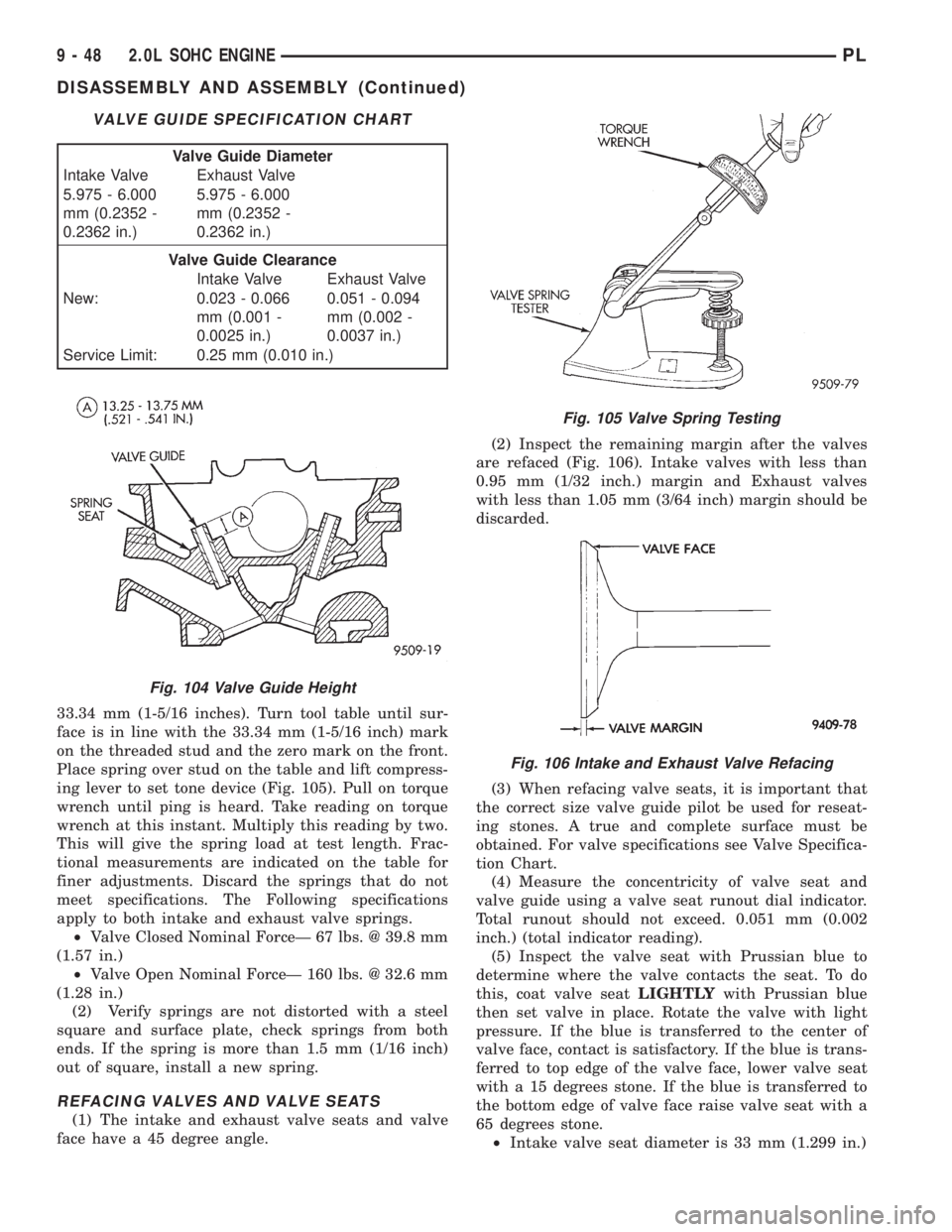
33.34 mm (1-5/16 inches). Turn tool table until sur-
face is in line with the 33.34 mm (1-5/16 inch) mark
on the threaded stud and the zero mark on the front.
Place spring over stud on the table and lift compress-
ing lever to set tone device (Fig. 105). Pull on torque
wrench until ping is heard. Take reading on torque
wrench at this instant. Multiply this reading by two.
This will give the spring load at test length. Frac-
tional measurements are indicated on the table for
finer adjustments. Discard the springs that do not
meet specifications. The Following specifications
apply to both intake and exhaust valve springs.
²Valve Closed Nominal ForceÐ 67 lbs. @ 39.8 mm
(1.57 in.)
²Valve Open Nominal ForceÐ 160 lbs. @ 32.6 mm
(1.28 in.)
(2) Verify springs are not distorted with a steel
square and surface plate, check springs from both
ends. If the spring is more than 1.5 mm (1/16 inch)
out of square, install a new spring.
REFACING VALVES AND VALVE SEATS
(1) The intake and exhaust valve seats and valve
face have a 45 degree angle.(2) Inspect the remaining margin after the valves
are refaced (Fig. 106). Intake valves with less than
0.95 mm (1/32 inch.) margin and Exhaust valves
with less than 1.05 mm (3/64 inch) margin should be
discarded.
(3) When refacing valve seats, it is important that
the correct size valve guide pilot be used for reseat-
ing stones. A true and complete surface must be
obtained. For valve specifications see Valve Specifica-
tion Chart.
(4) Measure the concentricity of valve seat and
valve guide using a valve seat runout dial indicator.
Total runout should not exceed. 0.051 mm (0.002
inch.) (total indicator reading).
(5) Inspect the valve seat with Prussian blue to
determine where the valve contacts the seat. To do
this, coat valve seatLIGHTLYwith Prussian blue
then set valve in place. Rotate the valve with light
pressure. If the blue is transferred to the center of
valve face, contact is satisfactory. If the blue is trans-
ferred to top edge of the valve face, lower valve seat
with a 15 degrees stone. If the blue is transferred to
the bottom edge of valve face raise valve seat with a
65 degrees stone.
²Intake valve seat diameter is 33 mm (1.299 in.)
VALVE GUIDE SPECIFICATION CHART
Valve Guide Diameter
Intake Valve Exhaust Valve
5.975 - 6.000
mm (0.2352 -
0.2362 in.)5.975 - 6.000
mm (0.2352 -
0.2362 in.)
Valve Guide Clearance
Intake Valve Exhaust Valve
New: 0.023 - 0.066
mm (0.001 -
0.0025 in.)0.051 - 0.094
mm (0.002 -
0.0037 in.)
Service Limit: 0.25 mm (0.010 in.)
Fig. 104 Valve Guide Height
Fig. 105 Valve Spring Testing
Fig. 106 Intake and Exhaust Valve Refacing
9 - 48 2.0L SOHC ENGINEPL
DISASSEMBLY AND ASSEMBLY (Continued)
Page 805 of 1200
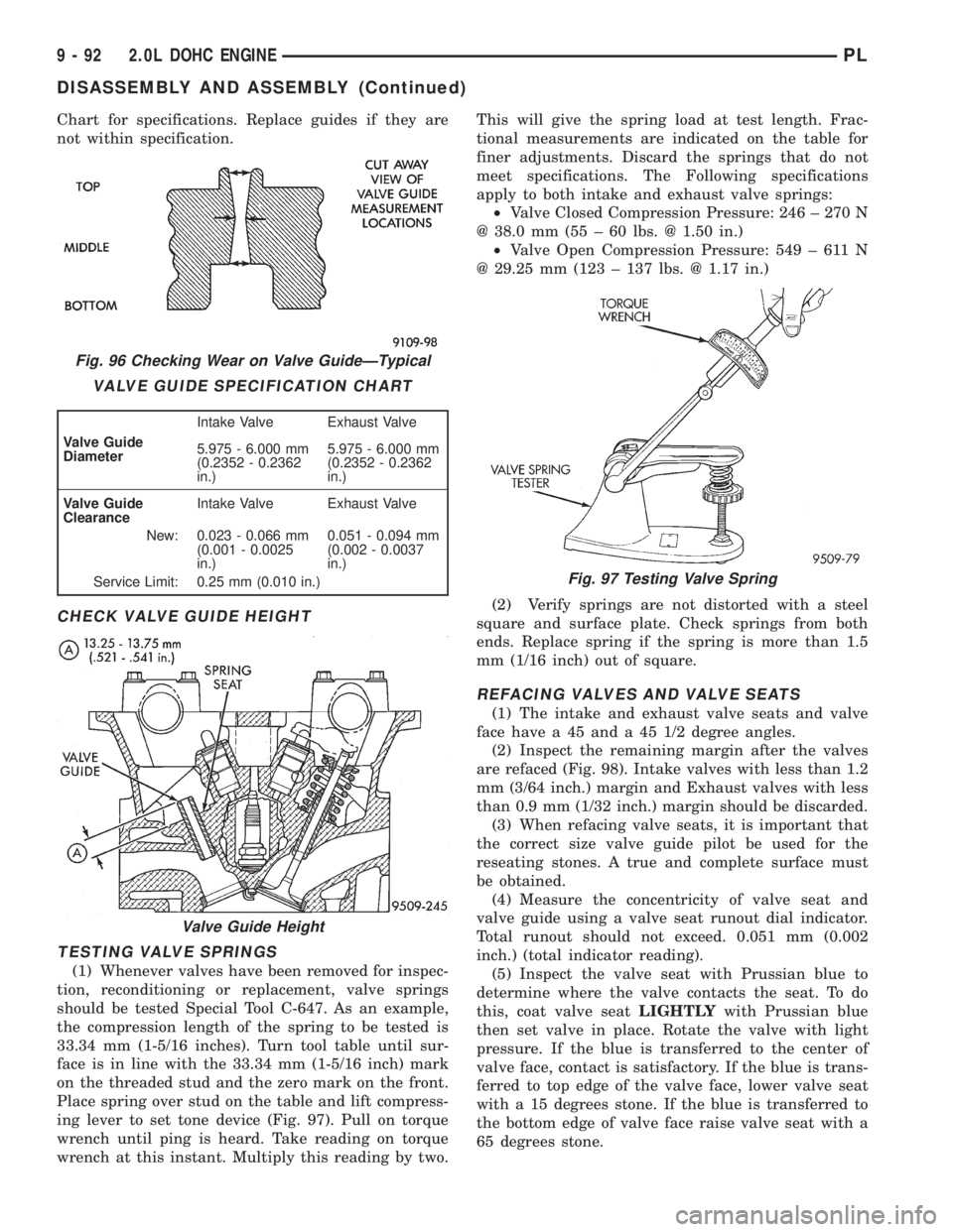
Chart for specifications. Replace guides if they are
not within specification.
CHECK VALVE GUIDE HEIGHT
TESTING VALVE SPRINGS
(1) Whenever valves have been removed for inspec-
tion, reconditioning or replacement, valve springs
should be tested Special Tool C-647. As an example,
the compression length of the spring to be tested is
33.34 mm (1-5/16 inches). Turn tool table until sur-
face is in line with the 33.34 mm (1-5/16 inch) mark
on the threaded stud and the zero mark on the front.
Place spring over stud on the table and lift compress-
ing lever to set tone device (Fig. 97). Pull on torque
wrench until ping is heard. Take reading on torque
wrench at this instant. Multiply this reading by two.This will give the spring load at test length. Frac-
tional measurements are indicated on the table for
finer adjustments. Discard the springs that do not
meet specifications. The Following specifications
apply to both intake and exhaust valve springs:
²Valve Closed Compression Pressure: 246 ± 270 N
@ 38.0 mm (55 ± 60 lbs. @ 1.50 in.)
²Valve Open Compression Pressure: 549 ± 611 N
@ 29.25 mm (123 ± 137 lbs. @ 1.17 in.)
(2) Verify springs are not distorted with a steel
square and surface plate. Check springs from both
ends. Replace spring if the spring is more than 1.5
mm (1/16 inch) out of square.
REFACING VALVES AND VALVE SEATS
(1) The intake and exhaust valve seats and valve
face have a 45 and a 45 1/2 degree angles.
(2) Inspect the remaining margin after the valves
are refaced (Fig. 98). Intake valves with less than 1.2
mm (3/64 inch.) margin and Exhaust valves with less
than 0.9 mm (1/32 inch.) margin should be discarded.
(3) When refacing valve seats, it is important that
the correct size valve guide pilot be used for the
reseating stones. A true and complete surface must
be obtained.
(4) Measure the concentricity of valve seat and
valve guide using a valve seat runout dial indicator.
Total runout should not exceed. 0.051 mm (0.002
inch.) (total indicator reading).
(5) Inspect the valve seat with Prussian blue to
determine where the valve contacts the seat. To do
this, coat valve seatLIGHTLYwith Prussian blue
then set valve in place. Rotate the valve with light
pressure. If the blue is transferred to the center of
valve face, contact is satisfactory. If the blue is trans-
ferred to top edge of the valve face, lower valve seat
with a 15 degrees stone. If the blue is transferred to
the bottom edge of valve face raise valve seat with a
65 degrees stone.
Fig. 96 Checking Wear on Valve GuideÐTypical
VALVE GUIDE SPECIFICATION CHART
Valve Guide
DiameterIntake Valve Exhaust Valve
5.975 - 6.000 mm
(0.2352 - 0.2362
in.)5.975 - 6.000 mm
(0.2352 - 0.2362
in.)
Valve Guide
ClearanceIntake Valve Exhaust Valve
New: 0.023 - 0.066 mm
(0.001 - 0.0025
in.)0.051 - 0.094 mm
(0.002 - 0.0037
in.)
Service Limit: 0.25 mm (0.010 in.)
Valve Guide Height
Fig. 97 Testing Valve Spring
9 - 92 2.0L DOHC ENGINEPL
DISASSEMBLY AND ASSEMBLY (Continued)
Page 854 of 1200
FUEL PUMP INLET STRAINER
REMOVAL
(1) Remove fuel pump module. Refer to Fuel Pump
Module Removal in this section.
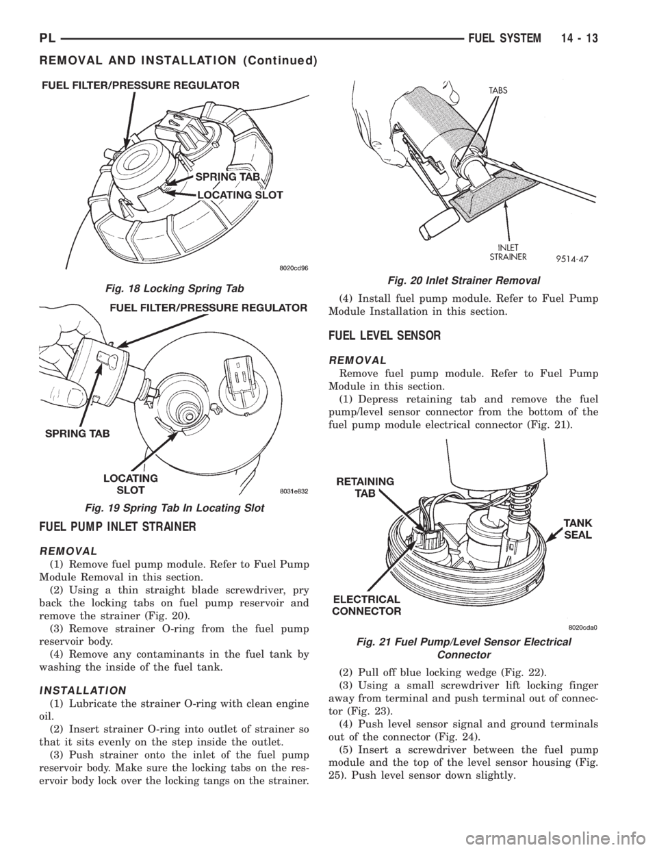
(2) Using a thin straight blade screwdriver, pry
back the locking tabs on fuel pump reservoir and
remove the strainer (Fig. 20).
(3) Remove strainer O-ring from the fuel pump
reservoir body.
(4) Remove any contaminants in the fuel tank by
washing the inside of the fuel tank.
INSTALLATION
(1) Lubricate the strainer O-ring with clean engine
oil.
(2) Insert strainer O-ring into outlet of strainer so
that it sits evenly on the step inside the outlet.
(3) P
ush strainer onto the inlet of the fuel pump
reservoir body. Make sure the locking tabs on the res-
ervoir body lock over the locking tangs on the strainer.
(4) Install fuel pump module. Refer to Fuel Pump
Module Installation in this section.
FUEL LEVEL SENSOR
REMOVAL
Remove fuel pump module. Refer to Fuel Pump
Module in this section.
(1) Depress retaining tab and remove the fuel
pump/level sensor connector from the bottom of the
fuel pump module electrical connector (Fig. 21).
(2) Pull off blue locking wedge (Fig. 22).
(3) Using a small screwdriver lift locking finger
away from terminal and push terminal out of connec-
tor (Fig. 23).
(4) Push level sensor signal and ground terminals
out of the connector (Fig. 24).
(5) Insert a screwdriver between the fuel pump
module and the top of the level sensor housing (Fig.
25). Push level sensor down slightly.
Fig. 18 Locking Spring Tab
Fig. 19 Spring Tab In Locating Slot
Fig. 20 Inlet Strainer Removal
Fig. 21 Fuel Pump/Level Sensor Electrical
Connector
PLFUEL SYSTEM 14 - 13
REMOVAL AND INSTALLATION (Continued)
Page 1001 of 1200
(8) Recheck fluid level after transaxle is at normal
operating temperature. The level should be in the
HOT region.
ALUMINUM THREAD REPAIR
Damaged or worn threads in the aluminum tran-
saxle case and valve body can be repaired by the use
of Heli-Coils. This repair consists of drilling out the
worn-out or damaged threads. Then tap the hole with
a Heli-Coil tap, and install a Heli-Coil insert into the
hole. This brings the hole back to its original thread
size.
Heli-Coil tools and inserts are readily available
from most automotive parts suppliers.
FLUSHING COOLERS AND TUBES
When a transaxle failure has contaminated the
fluid, the oil cooler(s) must be flushed. The cooler
bypass valve in the transaxle must be replaced also.
The torque converter must also be replaced with an
exchange unit. This will ensure that metal particles
or sludged oil are not later transferred back into the
reconditioned (or replaced) transaxle.
The recommended procedure for flushing the cool-
ers and tubes is to use Tool 6906A Cooler Flusher.
WARNING: WEAR PROTECTIVE EYEWEAR THAT
MEETS THE REQUIREMENTS OF OSHA AND ANSI
Z87.1±1968. WEAR STANDARD INDUSTRIAL RUB-
BER GLOVES.
KEEP LIGHTED CIGARETTES, SPARKS, FLAMES,
AND OTHER IGNITION SOURCES AWAY FROM THE
AREA TO PREVENT THE IGNITION OF COMBUSTI-
BLE LIQUIDS AND GASES. KEEP A CLASS (B) FIRE
EXTINGUISHER IN THE AREA WHERE THE
FLUSHER WILL BE USED.
KEEP THE AREA WELL VENTILATED.
DO NOT LET FLUSHING SOLVENT COME IN CON-
TACT WITH YOUR EYES OR SKIN: IF EYE CONTAM-
INATION OCCURS, FLUSH EYES WITH WATER FOR
15 TO 20 SECONDS. REMOVE CONTAMINATED
CLOTHING AND WASH AFFECTED SKIN WITH
SOAP AND WATER. SEEK MEDICAL ATTENTION.
COOLER FLUSH USING TOOL 6906A
(1) Remove cover plate filler plug on Tool 6906A.
Fill reservoir 1/2 to 3/4 full of fresh flushing solution.
Flushing solvents are petroleum based solutions gen-
erally used to clean automatic transmission compo-
nents.DO NOTuse solvents containing acids, water,
gasoline, or any other corrosive liquids.
(2) Reinstall filler plug on Tool 6906A.
(3) Verify pump power switch is turned OFF. Con-
nect red alligator clip to positive (+) battery post.
Connect black (-) alligator clip to a good ground.
(4) Disconnect the cooler lines at the transmission.NOTE: When flushing transmission cooler and
lines, ALWAYS reverse flush.
(5) Connect the BLUE pressure line to the OUT-
LET (From) cooler line.
(6) Connect the CLEAR return line to the INLET
(To) cooler line
(7) Turn pump ON for two to three minutes to
flush cooler(s) and lines. Monitor pressure readings
and clear return lines. Pressure readings should sta-
bilize below 20 psi. for vehicles equipped with a sin-
gle cooler and 30 psi. for vehicles equipped with dual
coolers. If flow is intermittent or exceeds these pres-
sures, replace cooler.
(8) Turn pump OFF.
(9) Disconnect CLEAR suction line from reservoir
at cover plate. Disconnect CLEAR return line at
cover plate, and place it in a drain pan.
(10) Turn pump ON for 30 seconds to purge flush-
ing solution from cooler and lines. Turn pump OFF.
(11) Place CLEAR suction line into a one quart
container of Mopar ATF Plus 3ttype 7176 automatic
transmission fluid.
(12) Turn pump ON until all transmission fluid is
removed from the one quart container and lines. This
purges any residual cleaning solvent from the trans-
mission cooler and lines. Turn pump OFF.
(13) Disconnect alligator clips from battery. Recon-
nect flusher lines to cover plate, and remove flushing
adapters from cooler lines.
OIL PUMP VOLUME CHECK
After the new or repaired transmission has been
installed, fill to the proper level with Mopar ATF
PLUS 3 (Type 7176) automatic transmission fluid.
The volume should be checked using the following
procedure:
(1) Disconnect theFrom coolerline at the trans-
mission and place a collecting container under the
disconnected line.
CAUTION: With the fluid set at the proper level,
fluid collection should not exceed (1) quart or inter-
nal damage to the transmission may occur.
(2) Run the engineat curb idle speed, with the
shift selector in neutral.
(3) If fluid flow is intermittent or it takes more
than 20 seconds to collect one quart of ATF, discon-
nect theTo Coolerline at the transaxle.
(4) Refill the transaxle to proper level and recheck
pump volume.
(5) If flow is found to be within acceptable limits,
replace the cooler. Then fill transmission to the
proper level, using Mopar ATF PLUS 3 (Type 7176)
automatic transmission fluid.
21 - 58 TRANSAXLEPL
SERVICE PROCEDURES (Continued)