Air filter replacement DODGE NEON 1999 Service Repair Manual
[x] Cancel search | Manufacturer: DODGE, Model Year: 1999, Model line: NEON, Model: DODGE NEON 1999Pages: 1200, PDF Size: 35.29 MB
Page 1139 of 1200

outlets in various combinations using the mode selec-
tor. There are 17 different mode selections possible.
Air flow velocity can be adjusted with the blower
speed selector switch on the instrument panel.
On A/C equipped vehicles the ambient air intake
can be controlled by opening and closing the recircu-
lating air door. When placed in RECIRC, air that is
inside vehicle is removed continuously and recircu-
lated through unit housing. Ambient air cannot be
controlled on vehicles without A/C. The system uses
outside air at all times.
The air conditioning compressor can be engaged by
turning the fan switch counterclockwise from the off
position. It can also be engaged by placing the mode
control in the defrost position. This will remove heat
and humidity from the air before it is directed
through or around the heater core.
SYSTEM OIL LEVEL
It is important to have the correct amount of oil in
the A/C system to ensure proper lubrication of the
compressor. Too little oil will result in damage to the
compressor. Too much oil will reduce the cooling
capacity of the system and consequently result in
higher discharge air temperatures.
NOTE: The oil used in the compressor is ND8 PAG
R-134a refrigerant oil. Only refrigerant oil of the
same type should be used to service the system.
Do not use any other oil. The oil container should
be kept tightly capped until it is ready for use.
Tightly cap afterwards to prevent contamination
from dirt and moisture. Refrigerant oil will quickly
absorb any moisture it comes in contact with. Spe-
cial effort must be used to keep all R-134a system
components moisture-free. Moisture in the oil is
very difficult to remove and will cause a reliability
problem with the compressor.
It will not be necessary to check oil level in the
compressor or to add oil unless there has been an oil
loss. Oil loss at a leak point will be evident by the
presence of a wet, shiny surface around the leak.
REFRIGERANT OIL LEVEL CHECK
When an air conditioning system is first assem-
bled, all components (except the compressor) are
refrigerant oil free. After the system has been
charged with R-134a refrigerant and operated, the oil
in the compressor is dispersed through the lines and
components. The evaporator, condenser, and filter-
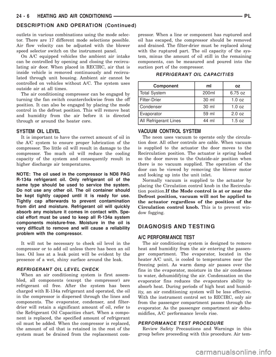
drier will retain a significant amount of oil, refer to
the Refrigerant Oil Capacities chart. When a compo-
nent is replaced, the specified amount of refrigerant
oil must be added. When the compressor is replaced,
the amount of oil that is retained in the rest of the
system must be drained from the replacement com-pressor. When a line or component has ruptured and
oil has escaped, the compressor should be removed
and drained. The filter-drier must be replaced along
with the ruptured part. The oil capacity of the sys-
tem, minus the amount of oil still in the remaining
components, can be measured and poured into the
suction port of the compressor.
VACUUM CONTROL SYSTEM
The neon uses vacuum to operate only the circula-
tion door. All other controls are cable. When vacuum
is supplied to the actuator the door moves to the
Recirculation position. The actuator is spring loaded
so the door moves to the Outside-air position when
there is no vacuum supplied. The operation of the
door can be viewed by removing the blower motor
and looking up into the unit inlet.
Normally vacuum is supplied to the actuator by
placing the Circulation control knob in the Recircula-
tion position.If the Mode control is at or near the
Defrost position, vacuum will not be applied to
the actuator regardless of the position of the
Circulation control knob.This is to prevent win-
dow fogging.
DIAGNOSIS AND TESTING
A/C PERFORMANCE TEST
The air conditioning system is designed to remove
heat and humidity from the air entering the passen-
ger compartment. The evaporator, located in the
heater A/C unit, is cooled to temperatures near the
freezing point. As warm damp air passes over the
fins in the evaporator, moisture in the air condenses
to water, dehumidifying the air. Condensation on the
evaporator fins reduces the evaporators ability to
absorb heat. During periods of high heat and humid-
ity, an air conditioning system will be less effective.
With the instrument control set to RECIRC, only air
from the passenger compartment passes through the
evaporator. As the passenger compartment air dehu-
midifies, A/C performance levels rise.
PERFORMANCE TEST PROCEDURE
Review Safety Precautions and Warnings in this
group before proceeding with this procedure. Air tem-
REFRIGERANT OIL CAPACITIES
Component ml oz
Total System 200ml 6.75 oz
Filter-Drier 30 ml 1.0 oz
Condenser 30 ml 1.0 oz
Evaporator 59 ml 2.0 oz
All Refrigerant Lines 44 ml 1.5 oz
24 - 6 HEATING AND AIR CONDITIONINGPL
DESCRIPTION AND OPERATION (Continued)
Page 1152 of 1200

(4) Remove two resistor block retaining screws.
The screw threads attaching the resistor block are
not full length. It is necessary to gently pry out the
resistor block while turning the screws counterclock-
wise enabling the threads to engages.
(5) Remove resistor block from vehicle.
INSTALLATION
For installation, reverse the above procedures.
BLOWER MOTOR WHEEL
The blower motor wheel is only serviced with the
blower motor. The wheel and the motor are balanced
as an assembly. If the blower motor wheel requires
replacement, the blower motor must also be replaced.
Refer to blower motor for replacement procedure.
COMPRESSOR
CAUTION: Add only new lubricant when system
requires additional lubricant. Do not use old
reclaimed lubricant.
REMOVAL
The A/C compressor may be unbolted and reposi-
tioned without discharging the refrigerant system.
Discharging is not necessary if removing the com-
pressor clutch/coil assembly, engine, cylinder head, or
alternator.
WARNING: REFRIGERANT PRESSURES REMAIN
HIGH EVEN THOUGH THE ENGINE MAY BE
TURNED OFF. DO NOT TWIST OR KINK THE
REFRIGERANT LINES WHEN REMOVING A FULLY
CHARGED COMPRESSOR. SAFETY GLASSES
MUST BE WORN.
(1) Disconnect battery negative cable.
(2) Loosen and remove drive belts, refer to Group
7, Engine Cooling.
(3) Using a R-134a refrigerant recovery machine,
remove the refrigerant from A/C system. If the com-
pressor is being replaced.
(4) Disconnect compressor clutch wire lead.
(5) Remove refrigerant lines from compressor, if
necessary.
(6) If system is left open place plug/cap over open
lines.
(7) Remove compressor attaching bolt.
(8) Remove compressor. If refrigerant lines were
not removed, lift compressor/clutch assembly and tie
it to a suitable component.
INSTALLATION
For installation, reverse the above procedures.
COMPRESSOR CLUTCH/COIL ASSEMBLY
Compressor assembly must be removed from mount-
ing. Although, refrigerant discharge is not necessary.
REMOVAL
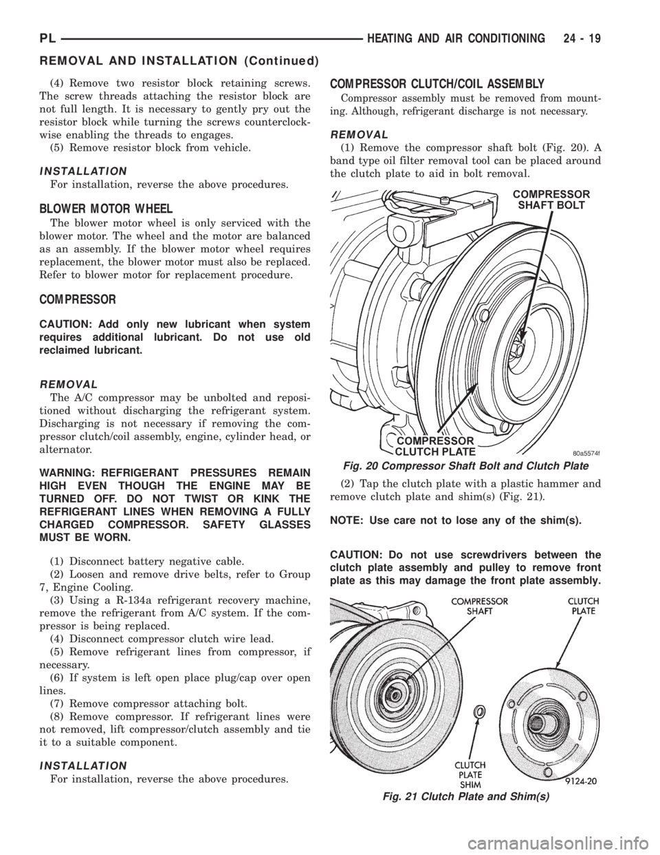
(1) Remove the compressor shaft bolt (Fig. 20). A
band type oil filter removal tool can be placed around
the clutch plate to aid in bolt removal.
(2) Tap the clutch plate with a plastic hammer and
remove clutch plate and shim(s) (Fig. 21).
NOTE: Use care not to lose any of the shim(s).
CAUTION: Do not use screwdrivers between the
clutch plate assembly and pulley to remove front
plate as this may damage the front plate assembly.
Fig. 20 Compressor Shaft Bolt and Clutch Plate
Fig. 21 Clutch Plate and Shim(s)
PLHEATING AND AIR CONDITIONING 24 - 19
REMOVAL AND INSTALLATION (Continued)