glove box DODGE NEON 1999 Service Repair Manual
[x] Cancel search | Manufacturer: DODGE, Model Year: 1999, Model line: NEON, Model: DODGE NEON 1999Pages: 1200, PDF Size: 35.29 MB
Page 220 of 1200
NOTE: BLACK OR DARK=0to75%state-of-charge
The battery is INADEQUATELY charged and must
be charged until green dot is visible, (12.4 volts or
greater) before the battery is tested or returned to
use. Refer to Causes of Battery Discharging in this
Group for more information.
NOTE: CLEAR COLOR = Replace Battery
WARNING: DO NOT CHARGE, ASSIST BOOST,
LOAD TEST, OR ADD WATER TO THE BATTERY
WHEN CLEAR COLOR DOT IS VISIBLE. PERSONAL
INJURY MAY OCCUR.
A clear color dot shows electrolyte level in battery
is below the test indicator (Fig. 1). Water cannot be
added to a maintenance free battery. The battery
must be replaced. A low electrolyte level may be
caused by an over charging condition. Refer to Gen-
erator Test Procedures on Vehicle.
CAUSES OF BATTERY DISCHARGING
It is normal to have a small 5 to 25 milliamperes
continuous electrical draw from the battery. This
draw will take place with the ignition in the OFF
position, and the courtesy, dome, storage compart-
ments, and engine compartment lights OFF. The con-
tinuous draw is due to various electronic features or
accessories that require electrical current with the
ignition OFF to function properly. When a vehicle is
not used over an extended period of approximately 20
days the IOD fuse should be pulled. The fuse is
located in the power distribution center. removal of
this fuse will reduce the level of battery discharge.
Refer to the Battery Diagnosis and Testing Table for
proper diagnosis.
ABNORMAL BATTERY DISCHARGING
²Corroded battery posts, cables or terminals.
²Loose or worn generator drive belt.
²Electrical loads that exceed the output of the
charging system due to equipment or accessories
installed after delivery.
²Slow driving speeds in heavy traffic conditions
or prolonged idling with high-amperage electrical
systems in use.
²Defective electrical circuit or component causing
excess Ignition Off Draw (IOD). Refer to Battery
Ignition Off Draw (IOD).
²Defective charging system.
²Defective battery.
BATTERY IGNITION OFF DRAW (IOD)
High current draw on the battery with the ignition
OFF will discharge a battery. After a dead battery is
recharged, the vehicle ignition off draw (IOD) shouldbe checked. To determine if a high current draw con-
dition exists first check the vehicle with a test lamp.
(1) Verify that all electrical accessories are OFF.
²Remove key from ignition switch
²Turn off all lights
²Trunk lid is closed
²Engine compartment hood lamp is disconnected
or lamp removed
²Glove box door is closed
²Sun visor vanity lights are OFF
²All doors are closed
²Allow the ignition key lamp system to time out
in approximately 30 seconds, if equipped.
(2) Disconnect battery negative cable (Fig. 4).
(3) Connect a 12 Volt test lamp, with a cold resis-
tance of 5-7 ohms, between the battery negative cable
clamp and the negative post (Fig. 5). If test lamp
goes out system is OK. If test lamp lights and stays
ON, go to Test Lamp Stays ON procedure.
TEST LAMP STAYS ON
There is either a short circuit or a fault in an elec-
tronic module. Two fuses in the Power Distribution
Center (PDC) feed the modules with ignition off
draw.
²Interior lamps fuse (10 Amp) (IOD) PDC.
²Fuel pump fuse (20 Amp) in PDC
(1) Remove interior lamp and fuel pump fuses. By
removing these fuses all ignition off draw from the
vehicle electronics will be disconnected. The test
lamp should go out. If test lamp goes out go to Step
2. If test lamp does not go out there is a current
draw or short circuit. Refer to Group 8W, Wiring Dia-
grams.
(2) Install the fuel pump fuse. If test lamp lights,
there is a current draw or short circuit in the A14
wiring circuit feed.
(a) Disconnect Powertrain Control Module.
(b) If test lamp goes out, replace Powertrain
Control Module.
(c) If test lamp does not go out, there is a cur-
rent draw or short circuit in the A14 circuit feed.
Refer to Group 8W, Wiring Diagrams.
(3) Install the interior lamp fuse. If test lamp
lights, there is a current draw or short circuit in the
M01 circuit. Refer to Group 8W, Wiring Diagrams. If
test lamp stays out, go to Step 4
(4) Use a multi-meter that has at least a range of
200 milliamperes. Install meter between the battery
negative cable and battery negative post (Fig. 6).
Carefully remove the test lamp without disconnecting
the meter. After all modules time-out the total vehi-
cle IOD should be less than 10 milliamperes. If igni-
tion off draw is more than 10 milliamperes go to Step
5.
(5) Remove both fuses from the Power Distribution
Center:
PLBATTERY 8A - 3
DIAGNOSIS AND TESTING (Continued)
Page 270 of 1200
INSTRUMENT PANEL AND SYSTEMS
CONTENTS
page page
GENERAL INFORMATION
INTRODUCTION......................... 1
DESCRIPTION AND OPERATION
DOME LAMP............................ 1
ELECTRONIC DIGITAL CLOCK.............. 1
INSTRUMENT CLUSTER................... 2
WARNING AND INDICATOR LAMPS......... 2
DIAGNOSIS AND TESTING
AIRBAG WARNING SYSTEM............... 2
BRAKE SYSTEM WARNING LAMP TEST...... 2
FOG LAMP SWITCH TEST................. 2
FUEL TANK SENDING UNIT TEST........... 3
HEADLAMP SWITCH TEST................. 3
HEATER A/C BLOWER SWITCH TEST........ 3
HEATER BLOWER SWITCH TEST............ 3
INDIVIDUAL GAUGE INOPERATIVE.......... 4
INSTRUMENT PANEL AND COMPONENTS.... 4
LOW OIL PRESSURE WARNING LAMP TEST . . 4
MULTIPLE GAUGE INOPERATIVE TEST....... 4
SEAT BELT REMINDER SYSTEM TEST....... 6
SENDING UNIT......................... 6
SERVICE ENGINE SOON INDICATOR......... 6
VEHICLE SPEED SENSOR TEST............. 6
REMOVAL AND INSTALLATION
ASH RECEIVER RETAINER AND LAMP....... 6
CENTER BEZEL.......................... 6
CIGAR LIGHTER RECEPTACLE.............. 6
CLUSTER LAMP......................... 7
CLUSTER PRINTED CIRCUIT BOARD........ 7CLUSTER.............................. 7
DOME LENS/LAMP....................... 8
FLOOR CONSOLE........................ 8
GAUGE................................ 8
GLOVE BOX DOOR/BIN................... 8
GLOVE BOX SWITCH/LAMP................ 9
HEADLAMP SWITCH..................... 9
HEATER A/C CONTROL BLOWER SWITCH . . . 10
HEATER A/C CONTROL LAMP............ 10
HEATER A/C CONTROL................... 9
HEATER CONTROL BLOWER SWITCH....... 10
IGNITION KEY LAMP.................... 10
INSTRUMENT PANEL.................... 10
LEFT TRIM PANEL...................... 10
ODOMETER............................ 10
RADIO................................ 12
REAR WINDOW DEFOGGER AND/OR FOG
LAMP SWITCH....................... 12
RIGHT TRIM PANEL..................... 12
SHIFTER KNOB......................... 13
STEERING COLUMN COVER LINER......... 13
STEERING COLUMN COVER.............. 13
STEERING COLUMN SHROUDS............ 13
TOP COVER AND CLUSTER BEZEL
REMOVAL........................... 14
TRANSMISSION RANGE INDICATOR LAMP . . 14
TRUNK LAMP/LENS..................... 14
VEHICLE SPEED SENSOR................ 14
GENERAL INFORMATION
INTRODUCTION
The purpose of the dash gauges and indicator
lamps is to keep the driver informed about the oper-
ating condition of the vehicle. If an abnormal condi-
tion occurs, the driver is informed by indicator lamp.
The driver can seek service before damage occurs.
Indicator lamps use ON/OFF switch functions for
operation, while gauges use a sending unit or sensor.
DESCRIPTION AND OPERATION
DOME LAMP
The Dome Lamp operates when a door is open or
when the headlamp switch is placed in courtesy posi-
tion.
ELECTRONIC DIGITAL CLOCK
The electronic digital clock is in the radio. The
clock and radio each use the display panel built into
the radio. A digital readout indicates the time in
hours and minutes whenever the ignition switch is in
the ON or ACC position.
PLINSTRUMENT PANEL AND SYSTEMS 8E - 1
Page 277 of 1200
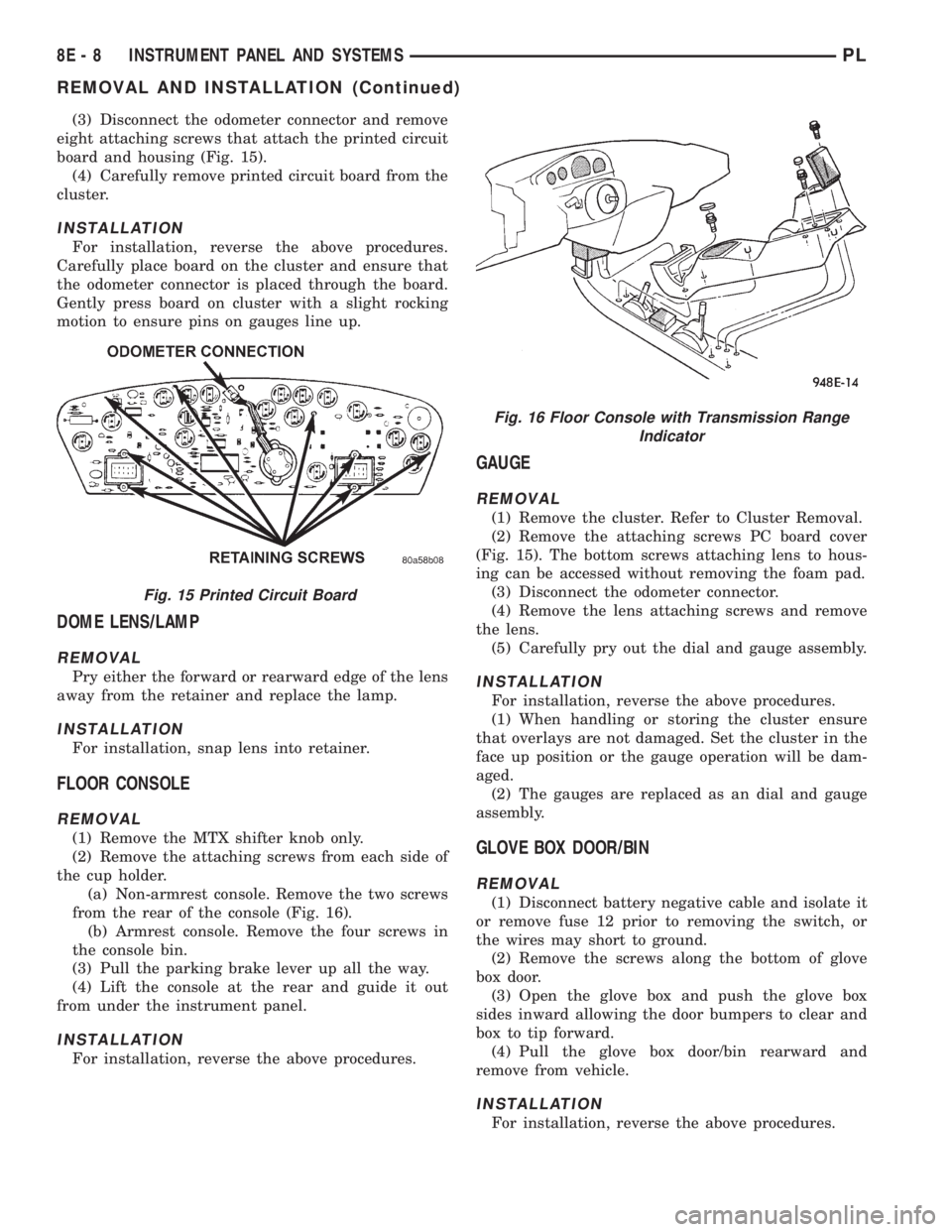
(3) Disconnect the odometer connector and remove
eight attaching screws that attach the printed circuit
board and housing (Fig. 15).
(4) Carefully remove printed circuit board from the
cluster.
INSTALLATION
For installation, reverse the above procedures.
Carefully place board on the cluster and ensure that
the odometer connector is placed through the board.
Gently press board on cluster with a slight rocking
motion to ensure pins on gauges line up.
DOME LENS/LAMP
REMOVAL
Pry either the forward or rearward edge of the lens
away from the retainer and replace the lamp.
INSTALLATION
For installation, snap lens into retainer.
FLOOR CONSOLE
REMOVAL
(1) Remove the MTX shifter knob only.
(2) Remove the attaching screws from each side of
the cup holder.
(a) Non-armrest console. Remove the two screws
from the rear of the console (Fig. 16).
(b) Armrest console. Remove the four screws in
the console bin.
(3) Pull the parking brake lever up all the way.
(4) Lift the console at the rear and guide it out
from under the instrument panel.
INSTALLATION
For installation, reverse the above procedures.
GAUGE
REMOVAL
(1) Remove the cluster. Refer to Cluster Removal.
(2) Remove the attaching screws PC board cover
(Fig. 15). The bottom screws attaching lens to hous-
ing can be accessed without removing the foam pad.
(3) Disconnect the odometer connector.
(4) Remove the lens attaching screws and remove
the lens.
(5) Carefully pry out the dial and gauge assembly.
INSTALLATION
For installation, reverse the above procedures.
(1) When handling or storing the cluster ensure
that overlays are not damaged. Set the cluster in the
face up position or the gauge operation will be dam-
aged.
(2) The gauges are replaced as an dial and gauge
assembly.
GLOVE BOX DOOR/BIN
REMOVAL
(1) Disconnect battery negative cable and isolate it
or remove fuse 12 prior to removing the switch, or
the wires may short to ground.
(2) Remove the screws along the bottom of glove
box door.
(3) Open the glove box and push the glove box
sides inward allowing the door bumpers to clear and
box to tip forward.
(4) Pull the glove box door/bin rearward and
remove from vehicle.
INSTALLATION
For installation, reverse the above procedures.
Fig. 15 Printed Circuit Board
Fig. 16 Floor Console with Transmission Range
Indicator
8E - 8 INSTRUMENT PANEL AND SYSTEMSPL
REMOVAL AND INSTALLATION (Continued)
Page 278 of 1200
GLOVE BOX SWITCH/LAMP
REMOVAL
(1) Disconnect battery negative cable and isolate it
or remove fuse 12 prior to removing the switch, or
wires may short to ground.
(2) Open the glove box and push the glove box
sides inward allowing the door bumpers to clear and
the box to tip rearward.
(3) Reach inside the opening and squeeze the
lamp/switch retainers until they are disengage.
(4) Pull the switch/lamp rearward and remove it.
Replace the lamp. To replace the switch disconnect
wire and replace the switch.
INSTALLATION
For installation, reverse the above procedures.
HEADLAMP SWITCH
REMOVAL
(1) Remove the steering column cover and liner.
(2) Remove the three screws securing headlamp
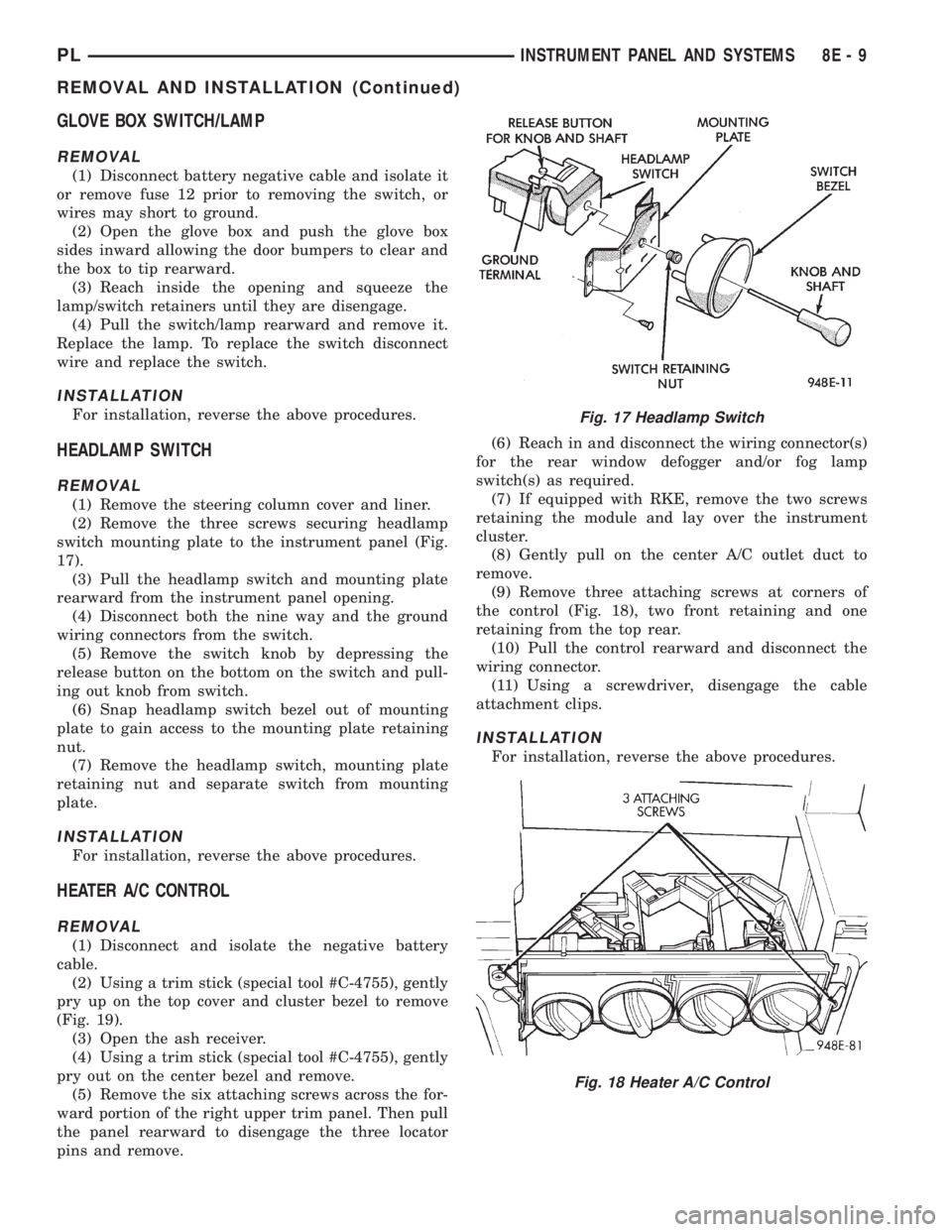
switch mounting plate to the instrument panel (Fig.
17).
(3) Pull the headlamp switch and mounting plate
rearward from the instrument panel opening.
(4) Disconnect both the nine way and the ground
wiring connectors from the switch.
(5) Remove the switch knob by depressing the
release button on the bottom on the switch and pull-
ing out knob from switch.
(6) Snap headlamp switch bezel out of mounting
plate to gain access to the mounting plate retaining
nut.
(7) Remove the headlamp switch, mounting plate
retaining nut and separate switch from mounting
plate.
INSTALLATION
For installation, reverse the above procedures.
HEATER A/C CONTROL
REMOVAL
(1) Disconnect and isolate the negative battery
cable.
(2) Using a trim stick (special tool #C-4755), gently
pry up on the top cover and cluster bezel to remove
(Fig. 19).
(3) Open the ash receiver.
(4) Using a trim stick (special tool #C-4755), gently
pry out on the center bezel and remove.
(5) Remove the six attaching screws across the for-
ward portion of the right upper trim panel. Then pull
the panel rearward to disengage the three locator
pins and remove.(6) Reach in and disconnect the wiring connector(s)
for the rear window defogger and/or fog lamp
switch(s) as required.
(7) If equipped with RKE, remove the two screws
retaining the module and lay over the instrument
cluster.
(8) Gently pull on the center A/C outlet duct to
remove.
(9) Remove three attaching screws at corners of
the control (Fig. 18), two front retaining and one
retaining from the top rear.
(10) Pull the control rearward and disconnect the
wiring connector.
(11) Using a screwdriver, disengage the cable
attachment clips.
INSTALLATION
For installation, reverse the above procedures.
Fig. 17 Headlamp Switch
Fig. 18 Heater A/C Control
PLINSTRUMENT PANEL AND SYSTEMS 8E - 9
REMOVAL AND INSTALLATION (Continued)
Page 285 of 1200
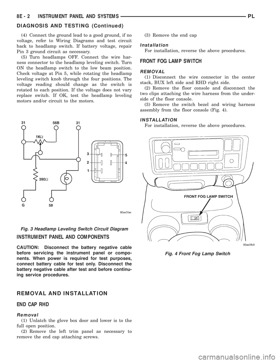
(4) Connect the ground lead to a good ground, if no
voltage, refer to Wiring Diagrams and test circuit
back to headlamp switch. If battery voltage, repair
Pin 3 ground circuit as necessary.
(5) Turn headlamps OFF. Connect the wire har-
ness connector to the headlamp leveling switch. Turn
ON the headlamp switch to the low beam position.
Check voltage at Pin 5, while rotating the headlamp
leveling switch knob through the four positions. The
voltage reading should change as the switch is
rotated to each position. If the voltage does not vary
replace switch. If OK, test the headlamp leveling
motors and/or circuit to the motors.
INSTRUMENT PANEL AND COMPONENTS
CAUTION: Disconnect the battery negative cable
before servicing the instrument panel or compo-
nents. When power is required for test purposes,
connect battery cable for test only. Disconnect the
battery negative cable after test and before continu-
ing service procedures.
REMOVAL AND INSTALLATION
END CAP RHD
Removal
(1) Unlatch the glove box door and lower is to the
full open position.
(2) Remove the left trim panel as necessary to
remove the end cap attaching screws.(3) Remove the end cap
Installation
For installation, reverse the above procedures.
FRONT FOG LAMP SWITCH
REMOVAL
(1) Disconnect the wire connector in the center
stack, BUX left side and RHD right side.
(2) Remove the floor console and disconnect the
two clips attaching the wire harness from the under-
side of the floor console.
(3) Remove the switch bezel and wiring harness
assembly from the floor console (Fig. 4).
INSTALLATION
For installation, reverse the above procedures.
Fig. 3 Headlamp Leveling Switch Circuit Diagram
Fig. 4 Front Fog Lamp Switch
8E - 2 INSTRUMENT PANEL AND SYSTEMSPL
DIAGNOSIS AND TESTING (Continued)
Page 351 of 1200
BULB APPLICATION
INDEX
page page
GENERAL INFORMATION
INTRODUCTION......................... 8
SPECIFICATIONS
EXTERIOR LAMPS........................ 8INTERIOR LAMPS........................ 8
GENERAL INFORMATION
INTRODUCTION
The following Bulb Application Tables list the lamp
title on the left side of the column and trade number
or part number on the right.
CAUTION: Do not use bulbs that have a higher
candle power than the bulb listed in the Bulb Appli-
cation Table. Damage to lamp can result.
Do not touch halogen bulbs with fingers or other
possibly oily surfaces. Bulb life will be reduced.
If a halogen bulb is contaminated with oil, clean
bulb with denatured alcohol or ammonia based sol-
vent.
SPECIFICATIONS
EXTERIOR LAMPS
LAMP BULB
Back-up...............................P21W
Center High Mounted Stop..................921
Front Fog Lamp..........................H-3
Headlamp...............................H-4
License Plate...........................W5W
Front Turn Signal.....................P21/5W
Tail/Stop.............................P21/5W
Rear Turn Signal.......................P21W
Rear Fog Lamp.........................P21W
Citylight...............................T4W
Side Repeater...........................T4W
INTERIOR LAMPS
LAMP BULB
ABS.................................PC194
Airbag...............................PC194
AshTray................................161
Brake Warning System Indicator...........PC194
Cigar Lighter............................203
Climate Controls.........................203
Console Gear Selector......................161
Dome Light..............................578
Glove Box...............................194
High Beam Indicator....................PC194
Ignition Key.............................161
Instrument Cluster.....................PC194
Rear Cargo..............................912
Seat Belt Indicator.......................PC74
Service Engine Soon....................PC194
Turn Signal Indicator....................PC194
Underhood..............................105
Visor Vanity.........................6501966
Volts Indicator..........................PC74
8L - 8 LAMPSPL
Page 360 of 1200
DRIVER AIRBAG MODULE
REMOVAL
WARNING: DISCONNECT AND ISOLATE THE BAT-
TERY NEGATIVE (GROUND) CABLE BEFORE
BEGINNING ANY AIRBAG SYSTEM COMPONENT
REMOVAL OR INSTALLATION PROCEDURE. THIS
WILL DISABLE THE AIRBAG SYSTEM. FAILURE TO
DISCONNECT BATTERY COULD RESULT IN ACCI-
DENTAL AIRBAG DEPLOYMENT AND POSSIBLE
PERSONAL INJURY. ALLOW SYSTEM CAPACITOR
TO DISCHARGE FOR 2 MINUTES BEFORE REMOV-
ING ANY AIRBAG COMPONENTS.
When removing a deployed module, rubber gloves,
eye protection and long sleeved shirt should be worn,
as there may be deposits on the surface which could
irritate the skin and eyes.
(1) Disconnect and isolate the battery negative
cable.
(2) Remove speed control switches or covers from
steering wheel armature and disconnect the wires.
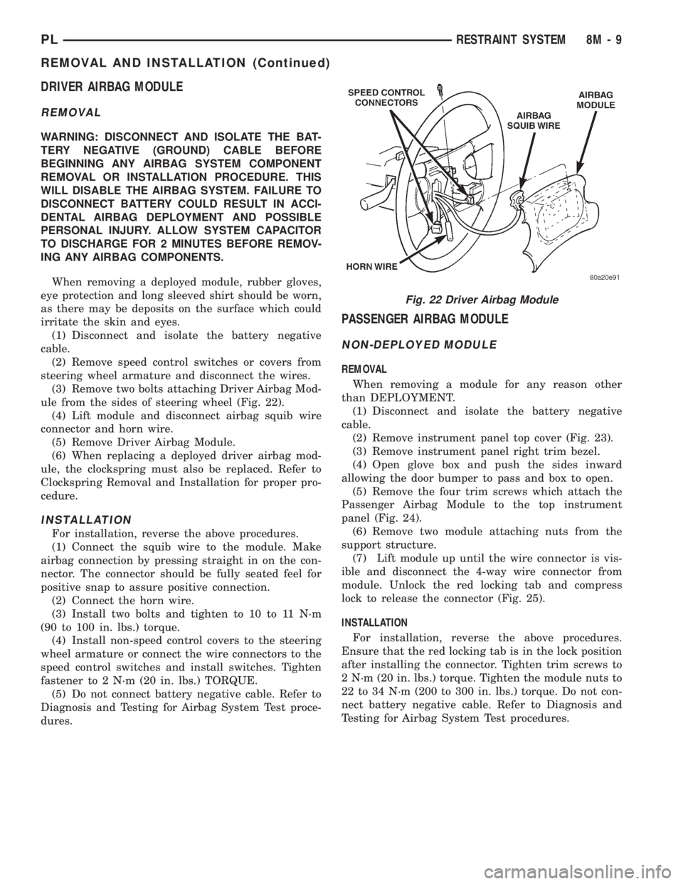
(3) Remove two bolts attaching Driver Airbag Mod-
ule from the sides of steering wheel (Fig. 22).
(4) Lift module and disconnect airbag squib wire
connector and horn wire.
(5) Remove Driver Airbag Module.
(6) When replacing a deployed driver airbag mod-
ule, the clockspring must also be replaced. Refer to
Clockspring Removal and Installation for proper pro-
cedure.
INSTALLATION
For installation, reverse the above procedures.
(1) Connect the squib wire to the module. Make
airbag connection by pressing straight in on the con-
nector. The connector should be fully seated feel for
positive snap to assure positive connection.
(2) Connect the horn wire.
(3) Install two bolts and tighten to 10 to 11 N´m
(90 to 100 in. lbs.) torque.
(4) Install non-speed control covers to the steering
wheel armature or connect the wire connectors to the
speed control switches and install switches. Tighten
fastener to 2 N´m (20 in. lbs.) TORQUE.
(5) Do not connect battery negative cable. Refer to
Diagnosis and Testing for Airbag System Test proce-
dures.
PASSENGER AIRBAG MODULE
NON-DEPLOYED MODULE
REMOVAL
When removing a module for any reason other
than DEPLOYMENT.
(1) Disconnect and isolate the battery negative
cable.
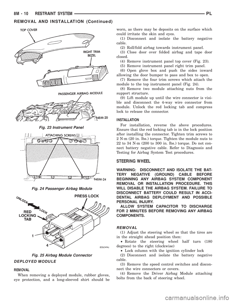
(2) Remove instrument panel top cover (Fig. 23).
(3) Remove instrument panel right trim bezel.
(4) Open glove box and push the sides inward
allowing the door bumper to pass and box to open.
(5) Remove the four trim screws which attach the
Passenger Airbag Module to the top instrument
panel (Fig. 24).
(6) Remove two module attaching nuts from the
support structure.
(7) Lift module up until the wire connector is vis-
ible and disconnect the 4-way wire connector from
module. Unlock the red locking tab and compress
lock to release the connector (Fig. 25).
INSTALLATION
For installation, reverse the above procedures.
Ensure that the red locking tab is in the lock position
after installing the connector. Tighten trim screws to
2 N´m (20 in. lbs.) torque. Tighten the module nuts to
22 to 34 N´m (200 to 300 in. lbs.) torque. Do not con-
nect battery negative cable. Refer to Diagnosis and
Testing for Airbag System Test procedures.
Fig. 22 Driver Airbag Module
PLRESTRAINT SYSTEM 8M - 9
REMOVAL AND INSTALLATION (Continued)
Page 361 of 1200
DEPLOYED MODULE
REMOVAL
When removing a deployed module, rubber gloves,
eye protection, and a long-sleeved shirt should beworn, as there may be deposits on the surface which
could irritate the skin and eyes.
(1) Disconnect and isolate the battery negative
cable.
(2) Roll/fold airbag towards instrument panel.
(3) Close door over folded airbag and tape door
closed.
(4) Remove instrument panel top cover (Fig. 23).
(5) Remove instrument panel right trim panel.
(6) Open glove box and push the sides inward
allowing the door bumper to pass and box to open.
(7) Remove the four trim screws which attach the
module to the top instrument panel (Fig. 24).
(8) Remove two module attaching nuts from the
support structure.
(9) Lift module up until the wire connector is visi-
ble and disconnect the 4-way wire connector from
module. Unlock the red locking tab and compress
lock to release the connector.
INSTALLATION
For installation, reverse the above procedures.
Ensure that the red locking tab is in the lock position
after installing the connector. Tighten trim screws to
2 N´m (20 in. lbs.) torque. Tighten the module nuts to
22 to 34 N´m (200 to 300 in. lbs.) torque. Do not con-
nect battery negative cable. Refer to Diagnosis and
Testing for Airbag System Test procedures.
STEERING WHEEL
WARNING: DISCONNECT AND ISOLATE THE BAT-
TERY NEGATIVE (GROUND) CABLE BEFORE
BEGINNING ANY AIRBAG SYSTEM COMPONENT
REMOVAL OR INSTALLATION PROCEDURE. THIS
WILL DISABLE THE AIRBAG SYSTEM. FAILURE TO
DISCONNECT BATTERY COULD RESULT IN ACCI-
DENTAL AIRBAG DEPLOYMENT AND POSSIBLE
PERSONAL INJURY.
ALLOW SYSTEM CAPACITOR TO DISCHARGE
FOR 2 MINUTES BEFORE REMOVING ANY AIRBAG
COMPONENTS.
REMOVAL
(1) Adjust the steering wheel so that the tires are
in the straight ahead position then:
²Rotate the steering wheel half turn (180
degrees) to the right (clockwise)
²Lock column with the ignition cylinder lock
(2) Disconnect and isolate the battery negative
cable.
(3) Remove the speed control switches and discon-
nect the wire connectors or covers.
(4) Remove the Driver Airbag Module attaching
bolts from the back of steering wheel.
Fig. 23 Instrument Panel
Fig. 24 Passenger Airbag Module
Fig. 25 Airbag Module Connector
8M - 10 RESTRAINT SYSTEMPL
REMOVAL AND INSTALLATION (Continued)
Page 410 of 1200
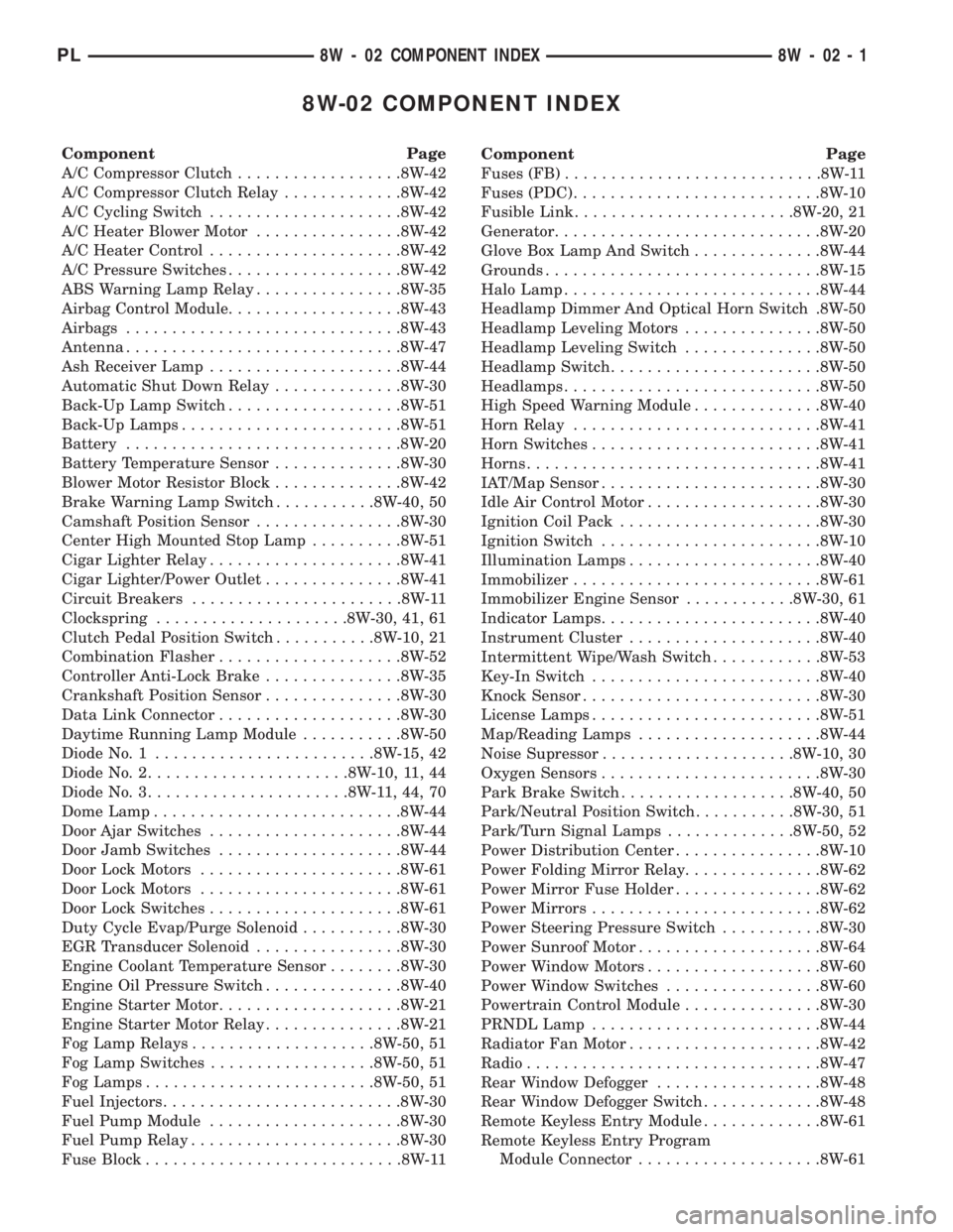
8W-02 COMPONENT INDEX
Component Page
A/C Compressor Clutch..................8W-42
A/C Compressor Clutch Relay.............8W-42
A/C Cycling Switch.....................8W-42
A/C Heater Blower Motor................8W-42
A/C Heater Control.....................8W-42
A/C Pressure Switches...................8W-42
ABS Warning Lamp Relay................8W-35
Airbag Control Module...................8W-43
Airbags..............................8W-43
Antenna..............................8W-47
Ash Receiver Lamp.....................8W-44
Automatic Shut Down Relay..............8W-30
Back-Up Lamp Switch...................8W-51
Back-Up Lamps........................8W-51
Battery..............................8W-20
Battery Temperature Sensor..............8W-30
Blower Motor Resistor Block..............8W-42
Brake Warning Lamp Switch...........8W-40, 50
Camshaft Position Sensor................8W-30
Center High Mounted Stop Lamp..........8W-51
Cigar Lighter Relay.....................8W-41
Cigar Lighter/Power Outlet...............8W-41
Circuit Breakers.......................8W-11
Clockspring.....................8W-30, 41, 61
Clutch Pedal Position Switch...........8W-10, 21
Combination Flasher....................8W-52
Controller Anti-Lock Brake...............8W-35
Crankshaft Position Sensor...............8W-30
Data Link Connector....................8W-30
Daytime Running Lamp Module...........8W-50
Diode No. 1........................8W-15, 42
Diode No. 2......................8W-10, 11, 44
Diode No. 3......................8W-11,44,70
Dome Lamp...........................8W-44
Door Ajar Switches.....................8W-44
Door Jamb Switches....................8W-44
Door Lock Motors......................8W-61
Door Lock Motors......................8W-61
Door Lock Switches.....................8W-61
Duty Cycle Evap/Purge Solenoid...........8W-30
EGR Transducer Solenoid................8W-30
Engine Coolant Temperature Sensor........8W-30
Engine Oil Pressure Switch...............8W-40
Engine Starter Motor....................8W-21
Engine Starter Motor Relay...............8W-21
Fog Lamp Relays....................8W-50, 51
Fog Lamp Switches..................8W-50, 51
Fog Lamps.........................8W-50, 51
Fuel Injectors..........................8W-30
Fuel Pump Module.....................8W-30
Fuel Pump Relay.......................8W-30
Fuse Block............................8W-11Component Page
Fuses (FB)............................8W-11
Fuses (PDC)...........................8W-10
Fusible Link........................8W-20, 21
Generator.............................8W-20
Glove Box Lamp And Switch..............8W-44
Grounds..............................8W-15
Halo Lamp............................8W-44
Headlamp Dimmer And Optical Horn Switch .8W-50
Headlamp Leveling Motors...............8W-50
Headlamp Leveling Switch...............8W-50
Headlamp Switch.......................8W-50
Headlamps............................8W-50
High Speed Warning Module..............8W-40
Horn Relay...........................8W-41
Horn Switches.........................8W-41
Horns................................8W-41
IAT/Map Sensor........................8W-30
Idle Air Control Motor...................8W-30
Ignition Coil Pack......................8W-30
Ignition Switch........................8W-10
Illumination Lamps.....................8W-40
Immobilizer...........................8W-61
Immobilizer Engine Sensor............8W-30, 61
Indicator Lamps........................8W-40
Instrument Cluster.....................8W-40
Intermittent Wipe/Wash Switch............8W-53
Key-In Switch.........................8W-40
Knock Sensor..........................8W-30
License Lamps.........................8W-51
Map/Reading Lamps....................8W-44
Noise Supressor.....................8W-10, 30
Oxygen Sensors........................8W-30
Park Brake Switch...................8W-40, 50
Park/Neutral Position Switch...........8W-30, 51
Park/Turn Signal Lamps..............8W-50, 52
Power Distribution Center................8W-10
Power Folding Mirror Relay...............8W-62
Power Mirror Fuse Holder................8W-62
Power Mirrors.........................8W-62
Power Steering Pressure Switch...........8W-30
Power Sunroof Motor....................8W-64
Power Window Motors...................8W-60
Power Window Switches.................8W-60
Powertrain Control Module...............8W-30
PRNDL Lamp.........................8W-44
Radiator Fan Motor.....................8W-42
Radio................................8W-47
Rear Window Defogger..................8W-48
Rear Window Defogger Switch.............8W-48
Remote Keyless Entry Module.............8W-61
Remote Keyless Entry Program
Module Connector....................8W-61
PL8W - 02 COMPONENT INDEX 8W - 02 - 1
Page 412 of 1200
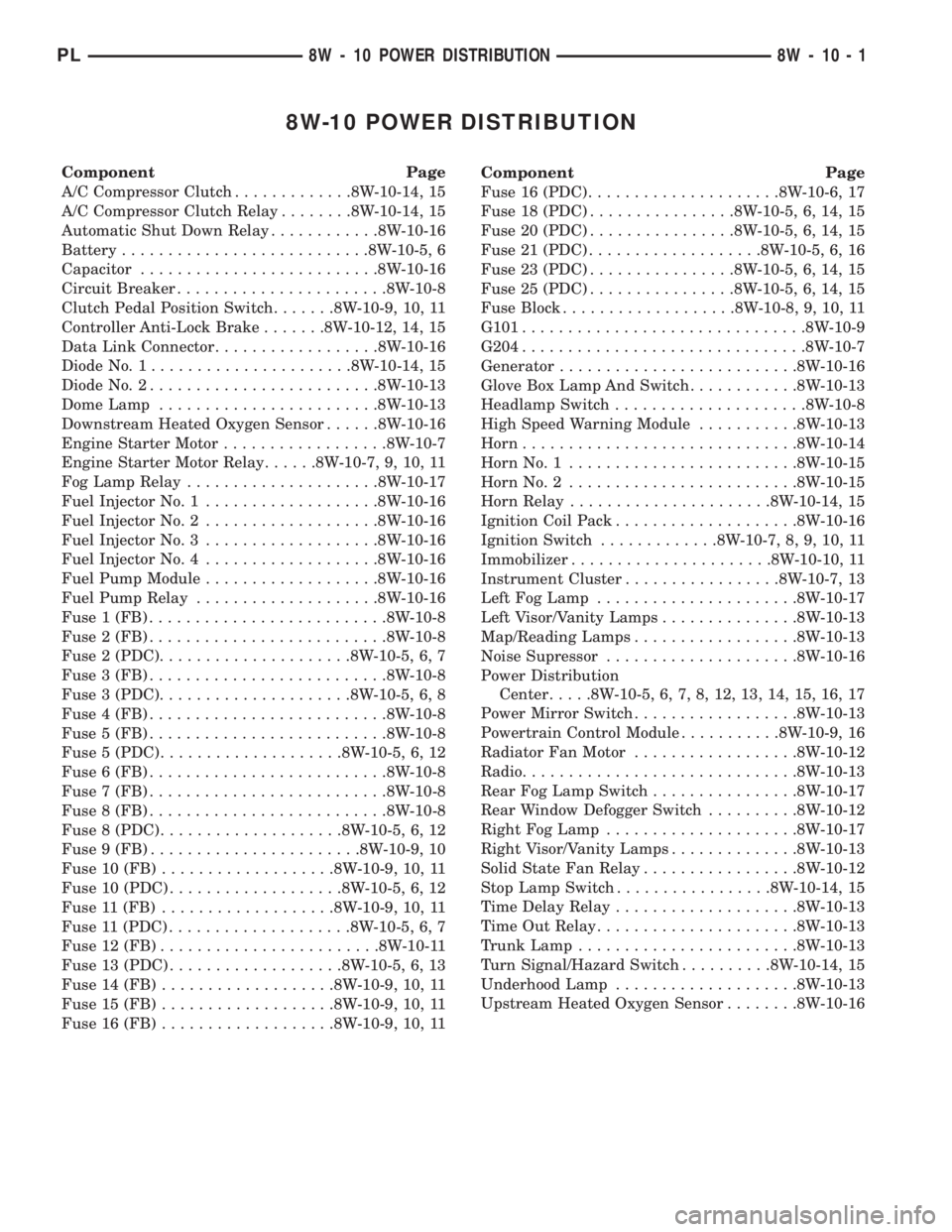
8W-10 POWER DISTRIBUTION
Component Page
A/C Compressor Clutch.............8W-10-14, 15
A/C Compressor Clutch Relay........8W-10-14, 15
Automatic Shut Down Relay............8W-10-16
Battery...........................8W-10-5, 6
Capacitor..........................8W-10-16
Circuit Breaker.......................8W-10-8
Clutch Pedal Position Switch.......8W-10-9, 10, 11
Controller Anti-Lock Brake.......8W-10-12, 14, 15
Data Link Connector..................8W-10-16
Diode No. 1......................8W-10-14, 15
Diode No. 2.........................8W-10-13
Dome Lamp........................8W-10-13
Downstream Heated Oxygen Sensor......8W-10-16
Engine Starter Motor..................8W-10-7
Engine Starter Motor Relay......8W-10-7, 9, 10, 11
Fog Lamp Relay.....................8W-10-17
Fuel Injector No. 1...................8W-10-16
Fuel Injector No. 2...................8W-10-16
Fuel Injector No. 3...................8W-10-16
Fuel Injector No. 4...................8W-10-16
Fuel Pump Module...................8W-10-16
Fuel Pump Relay....................8W-10-16
Fuse 1 (FB)..........................8W-10-8
Fuse 2 (FB)..........................8W-10-8
Fuse 2 (PDC).....................8W-10-5, 6, 7
Fuse 3 (FB)..........................8W-10-8
Fuse 3 (PDC).....................8W-10-5, 6, 8
Fuse 4 (FB)..........................8W-10-8
Fuse 5 (FB)..........................8W-10-8
Fuse 5 (PDC)....................8W-10-5, 6, 12
Fuse 6 (FB)..........................8W-10-8
Fuse 7 (FB)..........................8W-10-8
Fuse 8 (FB)..........................8W-10-8
Fuse 8 (PDC)....................8W-10-5, 6, 12
Fuse 9 (FB).......................8W-10-9, 10
Fuse 10 (FB)...................8W-10-9, 10, 11
Fuse 10 (PDC)...................8W-10-5, 6, 12
Fuse 11 (FB)...................8W-10-9, 10, 11
Fuse 11 (PDC)....................8W-10-5, 6, 7
Fuse 12 (FB)........................8W-10-11
Fuse 13 (PDC)...................8W-10-5, 6, 13
Fuse 14 (FB)...................8W-10-9, 10, 11
Fuse 15 (FB)...................8W-10-9, 10, 11
Fuse 16 (FB)...................8W-10-9, 10, 11Component Page
Fuse 16 (PDC).....................8W-10-6, 17
Fuse 18 (PDC)................8W-10-5, 6, 14, 15
Fuse 20 (PDC)................8W-10-5, 6, 14, 15
Fuse 21 (PDC)...................8W-10-5, 6, 16
Fuse 23 (PDC)................8W-10-5, 6, 14, 15
Fuse 25 (PDC)................8W-10-5, 6, 14, 15
Fuse Block...................8W-10-8, 9, 10, 11
G101...............................8W-10-9
G204...............................8W-10-7
Generator..........................8W-10-16
Glove Box Lamp And Switch............8W-10-13
Headlamp Switch.....................8W-10-8
High Speed Warning Module...........8W-10-13
Horn..............................8W-10-14
Horn No. 1.........................8W-10-15
Horn No. 2.........................8W-10-15
Horn Relay......................8W-10-14, 15
Ignition Coil Pack....................8W-10-16
Ignition Switch.............8W-10-7, 8, 9, 10, 11
Immobilizer......................8W-10-10, 11
Instrument Cluster.................8W-10-7, 13
Left Fog Lamp......................8W-10-17
Left Visor/Vanity Lamps...............8W-10-13
Map/Reading Lamps..................8W-10-13
Noise Supressor.....................8W-10-16
Power Distribution
Center.....8W-10-5, 6, 7, 8, 12, 13, 14, 15, 16, 17
Power Mirror Switch..................8W-10-13
Powertrain Control Module...........8W-10-9, 16
Radiator Fan Motor..................8W-10-12
Radio..............................8W-10-13
Rear Fog Lamp Switch................8W-10-17
Rear Window Defogger Switch..........8W-10-12
Right Fog Lamp.....................8W-10-17
Right Visor/Vanity Lamps..............8W-10-13
Solid State Fan Relay.................8W-10-12
Stop Lamp Switch.................8W-10-14, 15
Time Delay Relay....................8W-10-13
Time Out Relay......................8W-10-13
Trunk Lamp........................8W-10-13
Turn Signal/Hazard Switch..........8W-10-14, 15
Underhood Lamp....................8W-10-13
Upstream Heated Oxygen Sensor........8W-10-16
PL8W - 10 POWER DISTRIBUTION 8W - 10 - 1