keyless entry DODGE NEON 1999 Service Repair Manual
[x] Cancel search | Manufacturer: DODGE, Model Year: 1999, Model line: NEON, Model: DODGE NEON 1999Pages: 1200, PDF Size: 35.29 MB
Page 221 of 1200
²Fuel pump fuse (20 Amp)
²Interior lamps fuse (10 Amp)
(6) If there is any reading with fuses removed
there is a current draw or short circuit in the wiring.
Refer to Group 8W, Wiring Diagrams. If OK go to
Step 7.
(7) Install interior lamp fuse. After installing fuse,
the current can reach 250 milliamperes. After time-out the reading should not exceed 8 milliamperes. If
NOT OK go to Step 8. If OK go to Step 9.
²Ignition key lamp system
²Radio
²Remote keyless entry module, if equipped
(8) Disconnect radio and ignition switch key lamp
one component at time, to see if any component is at
fault. If the high reading is not eliminated there is a
short circuit in the wiring. Refer to Group 8W, Wir-
ing Diagrams.
CAUTION: Always disconnect the meter before
opening a door.
(9) Remove interior lamps fuse and install the fuel
pump fuse. The reading should be between 1-3 milli-
amperes. If reading is higher than 3 milliamperes:
(a) Disconnect Powertrain Control Module.
(b) If reading drops to zero, replace Powertrain
Control Module.
(c) If reading remains the same there is a cur-
rent draw or short circuit in the A14 circuit. Refer
to Group 8W, Wiring Diagrams.
BATTERY DIAGNOSIS AND TESTING
STEPS POSSIBLE CAUSE CORRECTION
VISUAL INSPECTION
Check for possible damage to
battery and clean battery.(1) Loose battery post, Cracked
battery cover or case, Leaks or Any
other physical
(2) Battery OK.(1) Replace Battery
(2) Check state of charge. Refer to
Test Indicator.
TEST INDICATOR
Check Charge Eye Color(1) GREEN
(2) BLACK
(3) CLEAR(1) Battery is charged. Perform
Battery 0pen Circuit Voltage Test
(2) Perform Battery Charging
procedure.
(3) Replace Battery.
BATTERY OPEN CIRCUIT
VOLTAGE TEST(1) Battery is above 12.40 Volts
(2) Battery is below 12.40 Volts.(1) Perform the Battery Load Test.
(2) Perform Battery Charging
procedure.
BATTERY CHARGING (1) Battery accepted Charge.
(2) Battery will not accept charge(1) Ensure that the indicator eye is
GREEN and perform Battery 0pen
Circuit Voltage Test
(2) Perform Charging a Completely
Discharged Battery.
BATTERY LOAD TEST (1) Acceptable minimum voltage.
(2) Unacceptable minimum voltage(1) Battery is OK to put in use,
perform Battery Ignition Off Draw
Test.
(2) Replace Battery and perform
Battery Ignition Off Draw Test.
CHARGING A COMPLETELY
DISCHARGED BATTERY(1) Battery accepted charge.
(2) Battery will not accept charge.(1) Ensure that the indicator eye is
GREEN and perform Battery 0pen
Circuit Voltage Test.
(2) Replace Battery.
IGNITION OFF DRAW TEST (1) IOD is 5-25 Milliamperes.
(2) IOD Exceeds 25 Milliamperes.(1) Vehicle is normal.
(2) Eliminate excess IOD draw.
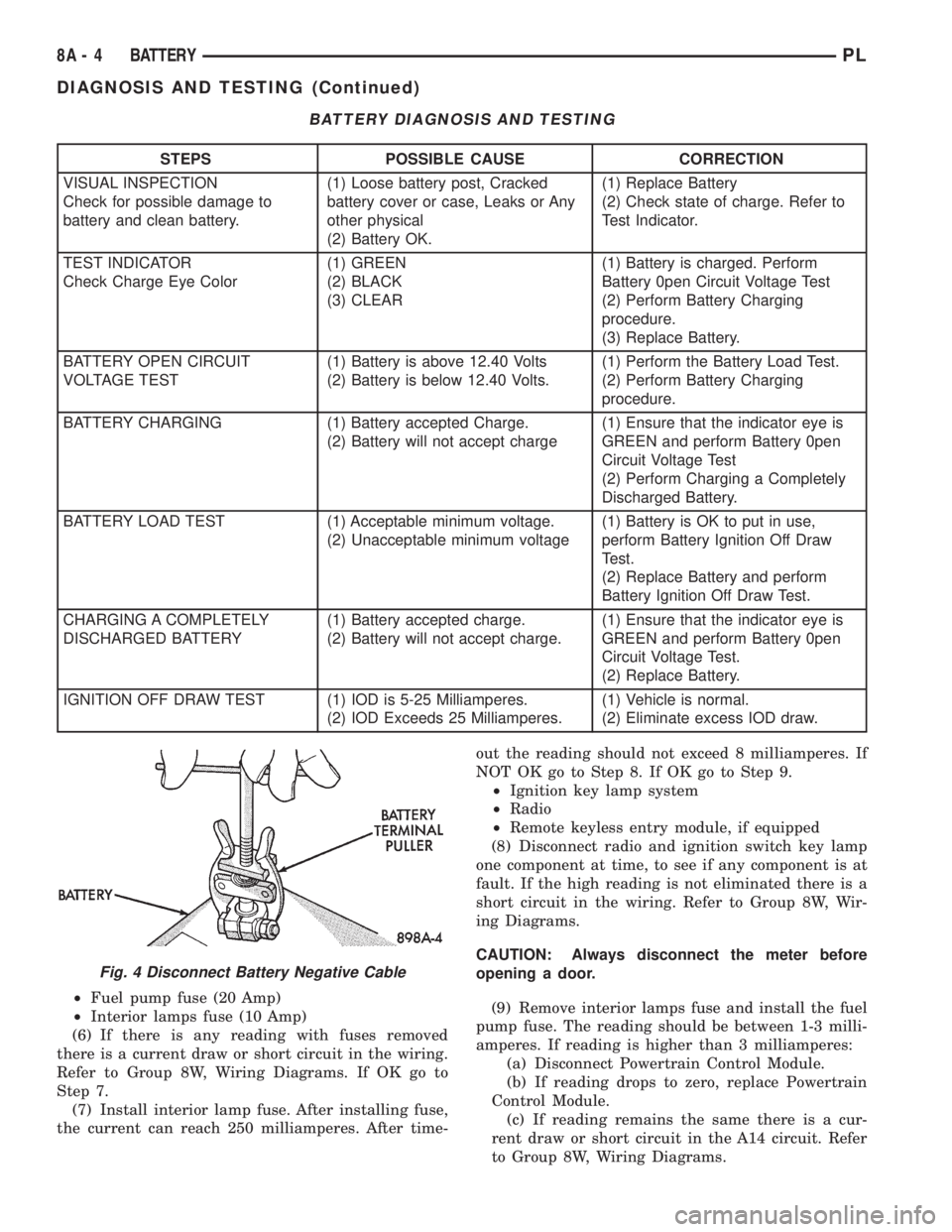
Fig. 4 Disconnect Battery Negative Cable
8A - 4 BATTERYPL
DIAGNOSIS AND TESTING (Continued)
Page 370 of 1200
POWER DOOR LOCKS
CONTENTS
page page
POWER DOOR LOCKS..................... 1REMOTE KEYLESS ENTRY.................. 3
POWER DOOR LOCKS
INDEX
page page
DESCRIPTION AND OPERATION
INTRODUCTION......................... 1
DIAGNOSIS AND TESTING
DOOR LOCK MOTOR..................... 1
DOOR LOCK SWITCH..................... 1WIRING................................ 1
REMOVAL AND INSTALLATION
DOOR LOCK MOTOR..................... 2
DOOR LOCK SWITCH..................... 2
DESCRIPTION AND OPERATION
INTRODUCTION
All doors can be locked or unlocked electrically by
operating the switch on either front door panels.
The rear doors can be locked or unlocked by actu-
ation of the front door switch, or can be locked or
unlocked mechanically and independently with their
respective locking knobs.
The front doors can be locked or unlocked mechan-
ically with the locking knob regardless of electrical
locking and unlocking actuation with the front door
knobs.
The right and left front door can be locked or
unlocked mechanically from the outside with the key
or electrically as described above.
CHILD PROTECTION LOCK
The child protection lock is on the rear door only.
The lock will disable the inside door handle from
opening the door when engaged. The lock is part of
the latch/lock assembly. The lock is engaged by mov-
ing a lever that is located on the rearward inside
edge of the door.
DIAGNOSIS AND TESTING
DOOR LOCK MOTOR
Make certain battery is in normal condition before
circuits are tested.To determine which motor is faulty, check each
individual door for electrical lock and unlock or dis-
connect the motor connectors one at a time, while
operating the door lock switch. In the event that
none of the motors work, the problem maybe caused
by a shorted motor, or a bad switch. Disconnecting
the defective motor will allow the others to work.
To test an individual door lock motor, disconnect
the electrical connector from the motor. To lock the
door, connect a 12 volt power source to the positive
pin of the lock motor and a ground wire to the other
pin (Fig. 1) To unlock the door reverse the wire con-
nections at the motor pin terminals. If these results
are NOT obtained, replace the door latch assembly.
DOOR LOCK SWITCH
Remove the switch from its mounting location.
Using an ohmmeter, refer to (Fig. 2) to determine if
continuity is correct in the Lock and Unlock switch
positions. If these results are not obtained, replace
the switch.
WIRING
The following wiring test sequence determines
whether or not voltage is continuous through the
body harness to switch.
(1) Remove left side switch from door trim panel.
(2) Carefully separate multiple terminal block on
wiring harness from switch body.
PLPOWER DOOR LOCKS 8P - 1
Page 372 of 1200
REMOTE KEYLESS ENTRY
INDEX
page page
GENERAL INFORMATION
INTRODUCTION......................... 3
DESCRIPTION AND OPERATION
VEHICLE ACCESS CODE (VAC)
PROGRAMMING........................ 3
DIAGNOSIS AND TESTING
REMOTE KEYLESS ENTRY CONDITION....... 4
REMOTE KEYLESS ENTRY SYSTEM......... 5
SERVICE PROCEDURES
HORN CHIRP CANCELLATION.............. 5PANIC FUNCTION CANCELLATION........... 5
PROGRAM REMOTE KEYLESS ENTRY
MODULE.............................. 5
REMOVAL AND INSTALLATION
REMOTE KEYLESS ENTRY MODULE......... 6
SPECIFICATIONS
RKE TRANSMITTER BATTERY.............. 6
RKE TRANSMITTER RANGE................ 6
GENERAL INFORMATION
INTRODUCTION
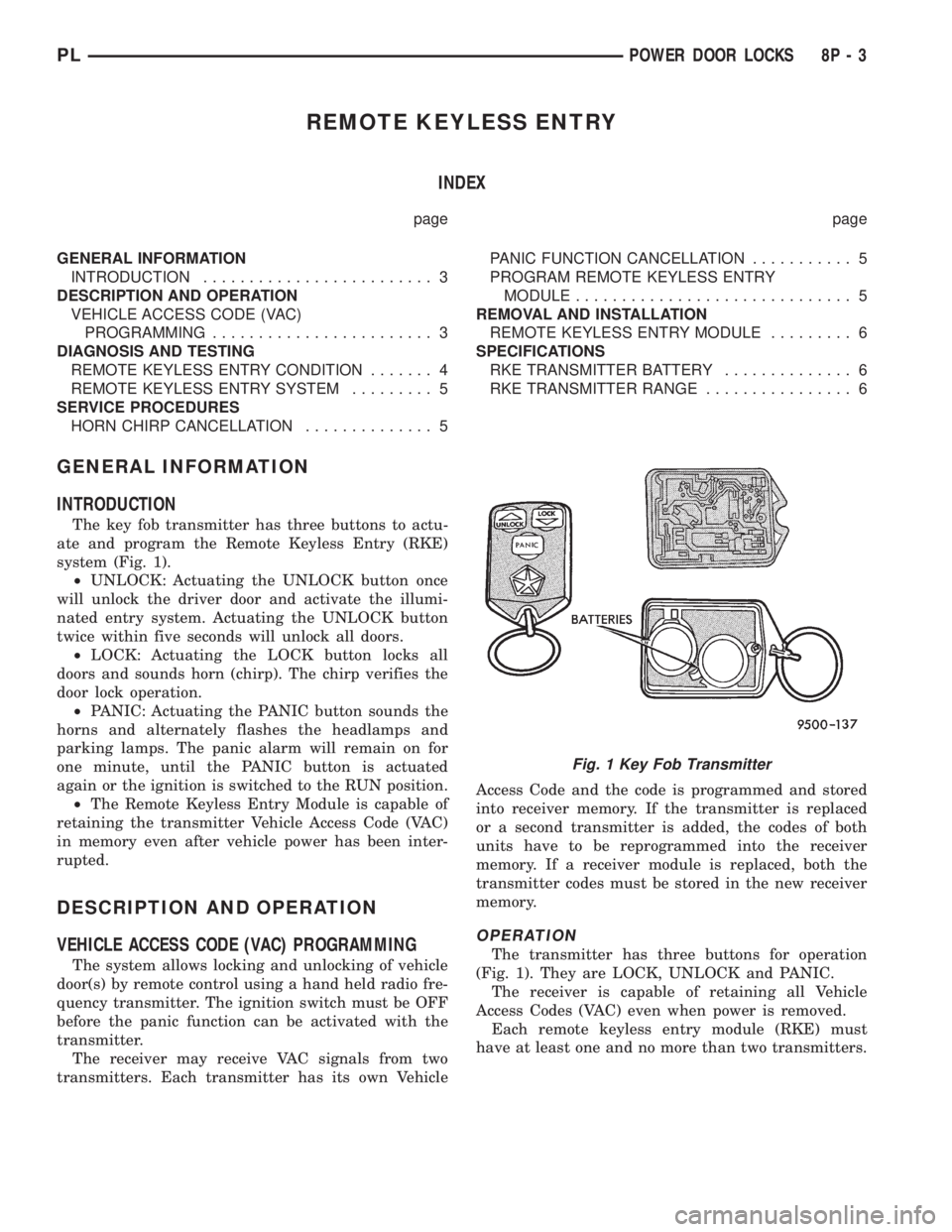
The key fob transmitter has three buttons to actu-
ate and program the Remote Keyless Entry (RKE)
system (Fig. 1).
²UNLOCK: Actuating the UNLOCK button once
will unlock the driver door and activate the illumi-
nated entry system. Actuating the UNLOCK button
twice within five seconds will unlock all doors.
²LOCK: Actuating the LOCK button locks all
doors and sounds horn (chirp). The chirp verifies the
door lock operation.
²PANIC: Actuating the PANIC button sounds the
horns and alternately flashes the headlamps and
parking lamps. The panic alarm will remain on for
one minute, until the PANIC button is actuated
again or the ignition is switched to the RUN position.
²The Remote Keyless Entry Module is capable of
retaining the transmitter Vehicle Access Code (VAC)
in memory even after vehicle power has been inter-
rupted.
DESCRIPTION AND OPERATION
VEHICLE ACCESS CODE (VAC) PROGRAMMING
The system allows locking and unlocking of vehicle
door(s) by remote control using a hand held radio fre-
quency transmitter. The ignition switch must be OFF
before the panic function can be activated with the
transmitter.
The receiver may receive VAC signals from two
transmitters. Each transmitter has its own VehicleAccess Code and the code is programmed and stored
into receiver memory. If the transmitter is replaced
or a second transmitter is added, the codes of both
units have to be reprogrammed into the receiver
memory. If a receiver module is replaced, both the
transmitter codes must be stored in the new receiver
memory.
OPERATION
The transmitter has three buttons for operation
(Fig. 1). They are LOCK, UNLOCK and PANIC.
The receiver is capable of retaining all Vehicle
Access Codes (VAC) even when power is removed.
Each remote keyless entry module (RKE) must
have at least one and no more than two transmitters.
Fig. 1 Key Fob Transmitter
PLPOWER DOOR LOCKS 8P - 3
Page 373 of 1200
DIAGNOSIS AND TESTING
REMOTE KEYLESS ENTRY CONDITION
Use an analog voltmeter for the following test.
REMOTE KEYLESS ENTRY GENERAL CHECKS
BEFORE OTHER CHECKS.
(1) Check if door locks operate properly. If not OK,
repair as necessary.
(2) Disconnect the wire connectors at the RKE
module Using a ohmmeter check for continuity
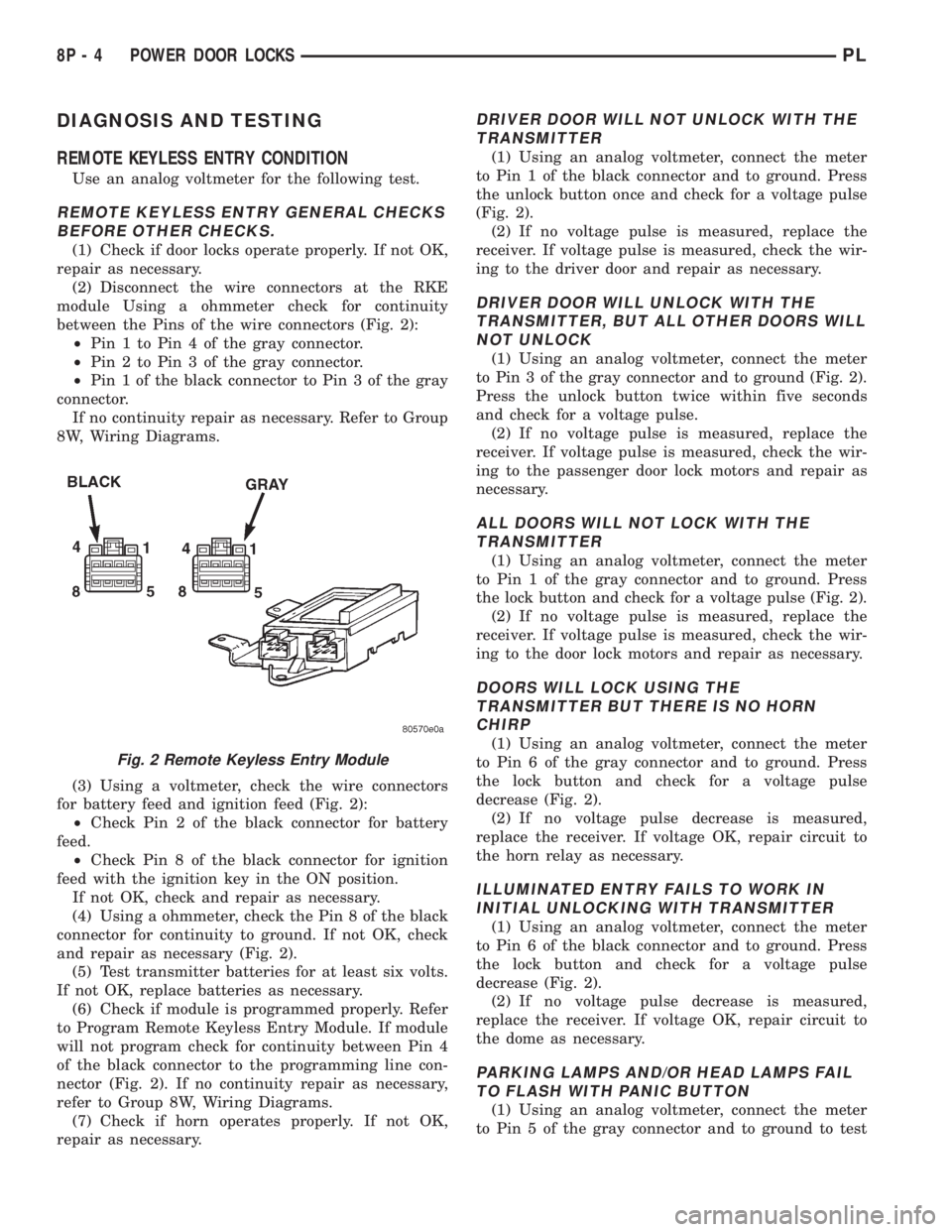
between the Pins of the wire connectors (Fig. 2):
²Pin 1 to Pin 4 of the gray connector.
²Pin 2 to Pin 3 of the gray connector.
²Pin 1 of the black connector to Pin 3 of the gray
connector.
If no continuity repair as necessary. Refer to Group
8W, Wiring Diagrams.
(3) Using a voltmeter, check the wire connectors
for battery feed and ignition feed (Fig. 2):
²Check Pin 2 of the black connector for battery
feed.
²Check Pin 8 of the black connector for ignition
feed with the ignition key in the ON position.
If not OK, check and repair as necessary.
(4) Using a ohmmeter, check the Pin 8 of the black
connector for continuity to ground. If not OK, check
and repair as necessary (Fig. 2).
(5) Test transmitter batteries for at least six volts.
If not OK, replace batteries as necessary.
(6) Check if module is programmed properly. Refer
to Program Remote Keyless Entry Module. If module
will not program check for continuity between Pin 4
of the black connector to the programming line con-
nector (Fig. 2). If no continuity repair as necessary,
refer to Group 8W, Wiring Diagrams.
(7) Check if horn operates properly. If not OK,
repair as necessary.
DRIVER DOOR WILL NOT UNLOCK WITH THE
TRANSMITTER
(1) Using an analog voltmeter, connect the meter
to Pin 1 of the black connector and to ground. Press
the unlock button once and check for a voltage pulse
(Fig. 2).
(2) If no voltage pulse is measured, replace the
receiver. If voltage pulse is measured, check the wir-
ing to the driver door and repair as necessary.
DRIVER DOOR WILL UNLOCK WITH THE
TRANSMITTER, BUT ALL OTHER DOORS WILL
NOT UNLOCK
(1) Using an analog voltmeter, connect the meter
to Pin 3 of the gray connector and to ground (Fig. 2).
Press the unlock button twice within five seconds
and check for a voltage pulse.
(2) If no voltage pulse is measured, replace the
receiver. If voltage pulse is measured, check the wir-
ing to the passenger door lock motors and repair as
necessary.
ALL DOORS WILL NOT LOCK WITH THE
TRANSMITTER
(1) Using an analog voltmeter, connect the meter
to Pin 1 of the gray connector and to ground. Press
the lock button and check for a voltage pulse (Fig. 2).
(2) If no voltage pulse is measured, replace the
receiver. If voltage pulse is measured, check the wir-
ing to the door lock motors and repair as necessary.
DOORS WILL LOCK USING THE
TRANSMITTER BUT THERE IS NO HORN
CHIRP
(1) Using an analog voltmeter, connect the meter
to Pin 6 of the gray connector and to ground. Press
the lock button and check for a voltage pulse
decrease (Fig. 2).
(2) If no voltage pulse decrease is measured,
replace the receiver. If voltage OK, repair circuit to
the horn relay as necessary.
ILLUMINATED ENTRY FAILS TO WORK IN
INITIAL UNLOCKING WITH TRANSMITTER
(1) Using an analog voltmeter, connect the meter
to Pin 6 of the black connector and to ground. Press
the lock button and check for a voltage pulse
decrease (Fig. 2).
(2) If no voltage pulse decrease is measured,
replace the receiver. If voltage OK, repair circuit to
the dome as necessary.
PARKING LAMPS AND/OR HEAD LAMPS FAIL
TO FLASH WITH PANIC BUTTON
(1) Using an analog voltmeter, connect the meter
to Pin 5 of the gray connector and to ground to test
Fig. 2 Remote Keyless Entry Module
8P - 4 POWER DOOR LOCKSPL
Page 374 of 1200
parking lamps out put. Press the panic button and
check for a voltage pulse (Fig. 2).
(2) If no voltage pulse is measured, replace the
receiver. If voltage OK, repair circuit to the parking
lamps as necessary.
(3) Connect the meter to Pin 5 of the black connec-
tor and to ground to test head lamps out put. Press
the panic button and check for a voltage pulse (Fig.
2).
(4) If no voltage pulse is measured, replace the
receiver. If voltage OK, repair circuit to the head
lamps as necessary.
REMOTE KEYLESS ENTRY SYSTEM
When trouble shooting problems with the Remote
Keyless Entry System, always verify that the power
door lock/unlock switches are functional. If the doors
do not lock/unlock refer to Group 8W, Wiring Dia-
gram for Pin and wiring locations.
If the following items do not work:
²Remote keyless entry system
²Radio/clock
²Door lock switches
A blown fuse is the probable cause. Check fuses 2,
3 and 11 in the fuse block. To check for a blown fuse,
pull the fuse out slightly, but maintain contact
between the fuse terminals and the terminals in fuse
block. Using the voltmeter probe, check both termi-
nals for 12 volts. If only one terminal measures bat-
tery voltage, the circuit breaker is defective and must
be replaced. If neither terminal measures battery
voltage, check the high current fuses 3 and 11 in the
Power Distribution Center (PDC). The PDC is located
in the engine compartment. If fuse(s) are NOT OK,
replace fuse(s) or repair as necessary. If fuses are
OK, check for an open or shorted circuit to the Power
Distribution Center, repair as needed.
SERVICE PROCEDURES
HORN CHIRP CANCELLATION
During the programming operation the horn chirp
can be disabled or enable using the following proce-
dure. One or both transmitters can be program to be
disabled or enable.
(1) Retrieve the programming line from the upper
edge of the passenger side cowl trim panel upper
edge. The RKE Programming Line is a green wire
with a red bullet connector.
(2) Using a jumper wire, ground the RKE pro-
gramming line.
(3) Turn ignition switch to the ON position.
(4) Press any button on the transmitter. The locks
will cycle to confirm programming,
(5) To disable or enable horn chirp press the lock
button on the transmitter four times and the hornwill sound to confirm programming. Press the lock
button on the second transmitter four times and the
horn will sound to confirm programming.
(6) Disconnect the programming line from ground.
This returns the system to its normal operation
mode.
(7) Replace any removed components. Return pro-
gramming line chirpto its original position. Check for
system operation.
PANIC FUNCTION CANCELLATION
During the programming operation the panic func-
tion can be disabled or enable using the following
procedure. One or both transmitters can be program
to be disabled or enable.
(1) Retrieve the programming line from the upper
edge of the passenger side cowl trim panel. The RKE
Program Line is a green wire with a red bullet con-
nector.
(2) Using a jumper wire, ground the RKE Pro-
gramming Line.
(3) Turn ignition switch to the ON position.
(4) Press any button on the transmitter. The locks
will cycle to confirm programming,
(5) To disable or enable panic function press the
panic button on the transmitter four times and the
horn will sound to confirm programming. Press the
panic button on the second transmitter four times
and the horn will sound to confirm programming.
(6) Disconnect the programming line from ground.
This returns the system to its normal operation
mode.
(7) Replace any removed components. Return the
programming line to its original position. Check for
system operation.
PROGRAM REMOTE KEYLESS ENTRY MODULE
(1) Retrieve the programming line from the upper
edge of the passenger side cowl trim panel. The RKE
Programming Line is a green wire with a red bullet
connector.
(2) Using a jumper wire, ground the RKE pro-
gramming line.
(3) Turn ignition switch to the ON position.
(4) Press any button on the transmitter to set
code. The locks will cycle to confirm programming. If
there is a second transmitter it must be set at this
time. Press any button on the second transmitter and
wait for the locks to cycle to confirm programming.
(5) Disconnect the programming line from ground.
This returns the system to its normal operation
mode.
(6) Replace all removed components. Return pro-
gramming line to its original position. Check for sys-
tem operation.
PLPOWER DOOR LOCKS 8P - 5
DIAGNOSIS AND TESTING (Continued)
Page 375 of 1200
REMOVAL AND INSTALLATION
REMOTE KEYLESS ENTRY MODULE
REMOVAL
(1) Remove the right trim panel, refer to Group
8E, Instrument Panel and Systems for proper
removal procedures.
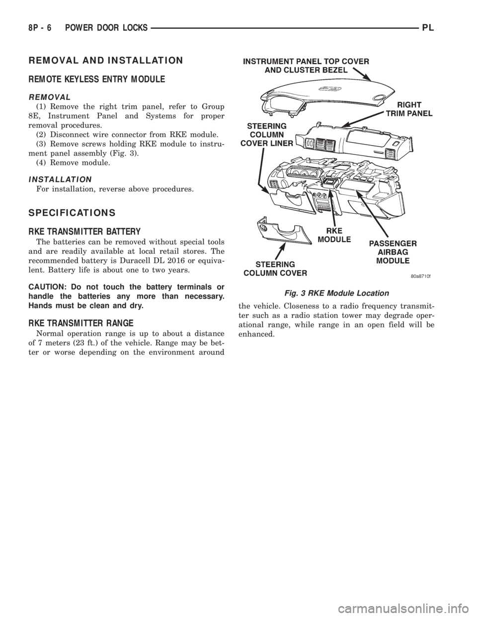
(2) Disconnect wire connector from RKE module.
(3) Remove screws holding RKE module to instru-
ment panel assembly (Fig. 3).
(4) Remove module.
INSTALLATION
For installation, reverse above procedures.
SPECIFICATIONS
RKE TRANSMITTER BATTERY
The batteries can be removed without special tools
and are readily available at local retail stores. The
recommended battery is Duracell DL 2016 or equiva-
lent. Battery life is about one to two years.
CAUTION: Do not touch the battery terminals or
handle the batteries any more than necessary.
Hands must be clean and dry.
RKE TRANSMITTER RANGE
Normal operation range is up to about a distance
of 7 meters (23 ft.) of the vehicle. Range may be bet-
ter or worse depending on the environment aroundthe vehicle. Closeness to a radio frequency transmit-
ter such as a radio station tower may degrade oper-
ational range, while range in an open field will be
enhanced.
Fig. 3 RKE Module Location
8P - 6 POWER DOOR LOCKSPL
Page 410 of 1200
8W-02 COMPONENT INDEX
Component Page
A/C Compressor Clutch..................8W-42
A/C Compressor Clutch Relay.............8W-42
A/C Cycling Switch.....................8W-42
A/C Heater Blower Motor................8W-42
A/C Heater Control.....................8W-42
A/C Pressure Switches...................8W-42
ABS Warning Lamp Relay................8W-35
Airbag Control Module...................8W-43
Airbags..............................8W-43
Antenna..............................8W-47
Ash Receiver Lamp.....................8W-44
Automatic Shut Down Relay..............8W-30
Back-Up Lamp Switch...................8W-51
Back-Up Lamps........................8W-51
Battery..............................8W-20
Battery Temperature Sensor..............8W-30
Blower Motor Resistor Block..............8W-42
Brake Warning Lamp Switch...........8W-40, 50
Camshaft Position Sensor................8W-30
Center High Mounted Stop Lamp..........8W-51
Cigar Lighter Relay.....................8W-41
Cigar Lighter/Power Outlet...............8W-41
Circuit Breakers.......................8W-11
Clockspring.....................8W-30, 41, 61
Clutch Pedal Position Switch...........8W-10, 21
Combination Flasher....................8W-52
Controller Anti-Lock Brake...............8W-35
Crankshaft Position Sensor...............8W-30
Data Link Connector....................8W-30
Daytime Running Lamp Module...........8W-50
Diode No. 1........................8W-15, 42
Diode No. 2......................8W-10, 11, 44
Diode No. 3......................8W-11,44,70
Dome Lamp...........................8W-44
Door Ajar Switches.....................8W-44
Door Jamb Switches....................8W-44
Door Lock Motors......................8W-61
Door Lock Motors......................8W-61
Door Lock Switches.....................8W-61
Duty Cycle Evap/Purge Solenoid...........8W-30
EGR Transducer Solenoid................8W-30
Engine Coolant Temperature Sensor........8W-30
Engine Oil Pressure Switch...............8W-40
Engine Starter Motor....................8W-21
Engine Starter Motor Relay...............8W-21
Fog Lamp Relays....................8W-50, 51
Fog Lamp Switches..................8W-50, 51
Fog Lamps.........................8W-50, 51
Fuel Injectors..........................8W-30
Fuel Pump Module.....................8W-30
Fuel Pump Relay.......................8W-30
Fuse Block............................8W-11Component Page
Fuses (FB)............................8W-11
Fuses (PDC)...........................8W-10
Fusible Link........................8W-20, 21
Generator.............................8W-20
Glove Box Lamp And Switch..............8W-44
Grounds..............................8W-15
Halo Lamp............................8W-44
Headlamp Dimmer And Optical Horn Switch .8W-50
Headlamp Leveling Motors...............8W-50
Headlamp Leveling Switch...............8W-50
Headlamp Switch.......................8W-50
Headlamps............................8W-50
High Speed Warning Module..............8W-40
Horn Relay...........................8W-41
Horn Switches.........................8W-41
Horns................................8W-41
IAT/Map Sensor........................8W-30
Idle Air Control Motor...................8W-30
Ignition Coil Pack......................8W-30
Ignition Switch........................8W-10
Illumination Lamps.....................8W-40
Immobilizer...........................8W-61
Immobilizer Engine Sensor............8W-30, 61
Indicator Lamps........................8W-40
Instrument Cluster.....................8W-40
Intermittent Wipe/Wash Switch............8W-53
Key-In Switch.........................8W-40
Knock Sensor..........................8W-30
License Lamps.........................8W-51
Map/Reading Lamps....................8W-44
Noise Supressor.....................8W-10, 30
Oxygen Sensors........................8W-30
Park Brake Switch...................8W-40, 50
Park/Neutral Position Switch...........8W-30, 51
Park/Turn Signal Lamps..............8W-50, 52
Power Distribution Center................8W-10
Power Folding Mirror Relay...............8W-62
Power Mirror Fuse Holder................8W-62
Power Mirrors.........................8W-62
Power Steering Pressure Switch...........8W-30
Power Sunroof Motor....................8W-64
Power Window Motors...................8W-60
Power Window Switches.................8W-60
Powertrain Control Module...............8W-30
PRNDL Lamp.........................8W-44
Radiator Fan Motor.....................8W-42
Radio................................8W-47
Rear Window Defogger..................8W-48
Rear Window Defogger Switch.............8W-48
Remote Keyless Entry Module.............8W-61
Remote Keyless Entry Program
Module Connector....................8W-61
PL8W - 02 COMPONENT INDEX 8W - 02 - 1
Page 430 of 1200
8W-11 FUSE BLOCK
Component Page
A/C Compressor Clutch Relay...........8W-11-14
A/C Cycling Switch................8W-11-12, 13
A/C Heater Blower Motor...........8W-11-12, 13
A/C Heater Control.............8W-11-17, 18, 19
ABS Warning Lamp Relay.............8W-11-14
Airbag Control Module..........8W-11-12, 13, 14
Ash Receiver Lamp.............8W-11-17, 18, 19
Back-Up Lamp Switch..............8W-11-12, 13
Cigar Lighter Relay.................8W-11-9, 20
Cigar Lighter/Power Outlet..........8W-11-7, 8, 9
Circuit Breaker.............8W-11-15, 16, 21, 22
Circuit Breaker (FB)..................8W-11-16
Controller Anti-Lock Brake.............8W-11-14
Daytime Running Lamp Module.........8W-11-15
Diode No.2.........................8W-11-23
Diode No.3.........................8W-11-23
Driver Door Lock Switch...............8W-11-11
Driver Power Window Switch........8W-11-15, 16
Duty Cycle Evap/Purge Solenoid.........8W-11-14
EGR Transducer Solenoid..............8W-11-14
Fog Lamp Switch..................8W-11-11,17
Front Fog Lamp Switch..............8W-11-8, 9
Fuel Pump Relay.....................8W-11-14
Fuse 1 (FB)......................8W-11-7, 8, 9
Fuse 2 (FB)......................8W-11-7, 8, 9
Fuse 3 (FB).........................8W-11-11
Fuse 4 (FB).........................8W-11-11
Fuse 5 (FB)......................8W-11-12, 13
Fuse 6 (FB)......................8W-11-12, 13
Fuse 7 (FB)......................8W-11-12, 13
Fuse 8 (FB)......................8W-11-12, 13
Fuse 9 (FB)....................8W-11-9, 14, 19
Fuse 10 (FB)........................8W-11-14
Fuse 11 (FB).....................8W-11-15, 16
Fuse 12 (FB)..............8W-11-7, 8, 14, 17, 18
Fuse 13 (PDC).......................8W-11-23
Fuse 14 (FB)........................8W-11-20
Fuse 15 (FB)........................8W-11-20
Fuse 16 (FB)........................8W-11-20
Fuse 17 (FB).....................8W-11-21, 22
Fuse 18 (FB).....................8W-11-21, 22
Fuse Block...........8W-11-2, 3, 4, 7, 8, 9, 11, 12,
13, 14, 15, 16, 17, 18, 19, 20, 21, 22, 23
Halo Lamp.........................8W-11-23
Headlamp Dimmer And Optical
Horn Switch...................8W-11-21, 22Component Page
Headlamp Leveling Switch.......8W-11-18, 19, 22
Headlamp Switch . .8W-11-7, 8, 9, 17, 18, 19, 21, 22,
High Speed Warning Module.........8W-11-12, 13
Immobilizer......................8W-11-11,16
Instrument Cluster.....8W-11-15, 16, 17, 18, 19, 23
Intermittent Wipe/Wash Switch.........8W-11-20
Left Front Door Jamb Switch...........8W-11-23
Left Front Side Marker Lamp...........8W-11-10
Left Headlamp....................8W-11-21, 22
Left Headlamp Leveling Motor..........8W-11-22
Left License Lamp..................8W-11-8, 9
Left Park/Turn Signal Lamp............8W-11-10
Left Tail/Stop Lamp.................8W-11-8, 9
Left Tail/Stop/Turn Signal Lamp..........8W-11-7
License Lamp........................8W-11-7
Map/Reading Lamps..................8W-11-23
Park/Neutral Position Switch........8W-11-12, 13
Passenger Door Lock Switch............8W-11-11
Passenger Power Window Switch.....8W-11-15, 16
Power Distribution Center...........8W-11-14, 23
Power Mirror Fuse Holder.............8W-11-16
Powertrain Control Module.............8W-11-14
PRNDL Lamp.................8W-11-17, 18, 19
Radio...............8W-11-7, 8, 9, 17, 18, 19, 20
Rear Fog Lamp Switch..........8W-11-18, 19, 22
Rear Window Defogger
Switch...............8W-11-12, 13, 17, 18, 19
Remote Keyless Entry Module......8W-11-7, 11, 15
Right Front Side Marker Lamp..........8W-11-10
Right Headlamp..................8W-11-21, 22
Right Headlamp Leveling Motor.........8W-11-22
Right License Lamp.................8W-11-8, 9
Right Park/Turn Signal Lamp...........8W-11-10
Right Tail/Stop Lamp................8W-11-8, 9
Right Tail/Stop/Turn Signal Lamp........8W-11-7
Sunroof Slide Switch..................8W-11-20
Sunroof Vent Switch..................8W-11-20
Time Delay Relay....................8W-11-23
Time Out Relay......................8W-11-23
Torque Converter Clutch Solenoid........8W-11-14
Turn Signal/Hazard Switch..........8W-11-12, 13
Vapor Canister Leak Detector...........8W-11-14
Wipe/Wash Switch....................8W-11-20
Wiper Motor........................8W-11-20
PL8W - 11 FUSE BLOCK 8W - 11 - 1
Page 436 of 1200

1FUSE15A
21
BATT A3
F30
16
RD
2FUSE15A
22
F33
20
PK/RD
HEADLAMP
SWITCH
4
L7
20
BK/YLL7
20
BK/YL
S218
L7
20
BK/YL
7C230
L7
20
BK/YL
4
RADIO
54
RADIO
L7
20
BK/YLL7
20
BK/YL
MODULE ENTRY
KEYLESS
REMOTE
L7
20
BK/YL
L7
18
BK/YL
222
LAMP LICENSE
L7
18
BK/YLL7
20
BK/YL
S306
L7
20
BK/YL
1
FUSE
BLOCK12
32
4A
FUSE
12
RKE
OTHER
E1
20
TN
9
2
1 0
FUSE
BLOCK
TO
C105 OUTLET POWER
LIGHTER/
CIGAR
C2C2
0 OFF
1 PARK
2 HEAD 1
1
2
C2
LAMP SIGNAL
TURN
STOP/
TAIL/
LEFT RIGHT
TAIL/
STOP/
TURN
SIGNAL
LAMP
A
(8W-11-10) (8W-41-4)(8W-11-2)
(8W-11-17)(8W-11-2)
(8W-51-5) (8W-61-7)(8W-47-2)(8W-47-2) (8W-10-8)
(8W-50-2)
(8W-50-9)
(8W-50-10)
(8W-51-5) (8W-51-5)
PL8W-11 FUSE/FUSE BLOCK
EXCEPT BUILT-UP-EXPORT8W - 11 - 7
8213J988W-1
Page 440 of 1200

FUSE
BLOCK
BATT A3
S214
24RD/YL16 F35
3SWITCH LOCK
DOOR
DRIVER PASSENGER
DOOR
LOCK
SWITCH
3
F35
16
RD/YL
F35
18
RD/YL
RD/YL18 F35 RD/YL16 F35
RD/YL16 F3524
23
10A
FUSE
4
20AFUSE
3
34
LHD RHD
1C231 C20511C231 C2051
RHD LHD
F35
16
RD/YL
REMOTE
KEYLESS
ENTRY
MODULE
2C1
RD/YL16 F35
F61
20
WT/OR
2
(EXCEPT BUILT-UP-EXPORT) SWITCH
LAMP
FOG
BUILT-UP-EXPORTEXCEPT
BUILT-UP-EXPORT
IMMOBILIZER
10C242
F35
16
RD/YL
(8W-10-8)
(8W-61-2)
(8W-61-10)
(8W-61-11) (8W-61-4)
(8W-61-10)
(8W-61-11)(8W-11-2)
(8W-11-3)
(8W-11-4)
(8W-61-6) (8W-50-12)
(8W-61-8)
PL8W-11 FUSE/FUSE BLOCK 8W - 11 - 11
8217J988W-1