roof rack DODGE NEON 1999 Service Repair Manual
[x] Cancel search | Manufacturer: DODGE, Model Year: 1999, Model line: NEON, Model: DODGE NEON 1999Pages: 1200, PDF Size: 35.29 MB
Page 1083 of 1200
BODY COMPONENTS
INDEX
page page
DIAGNOSIS AND TESTING
WATER LEAKS.......................... 3
WIND NOISE............................ 4
SERVICE PROCEDURES
HEAT STAKING.......................... 4
REMOVAL AND INSTALLATION
WINDOW REGULATORÐ4 DOOR........... 36
A-PILLAR TRIM.......................... 4
B-PILLAR APPLIQUEÐ2 DOOR.............. 5
B-PILLAR APPLIQUEÐ4 DOOR.............. 5
B-PILLAR TRIMÐ4 DOOR.................. 6
B-PILLAR WEATHERSTRIP CHANNEL......... 6
BODY VENT............................. 6
CARPET............................... 7
CHILD RESTRAINT SEAT BACK............. 8
CHILD SEAT MODULE..................... 8
COWL COVER........................... 7
DOOR HINGE........................... 9
DOOR LOCK CYLINDER.................. 10
DOOR OPENING TRIM WELT.............. 10
DOOR SILL TRIM........................ 10
DOOR................................. 9
FLOOR CONSOLE LATCH................. 11
FLOOR CONSOLE....................... 11
FRONT DOOR CHECK STOP............... 11
FRONT DOOR GLASSÐ2 DOOR............ 12
FRONT DOOR GLASSÐ4 DOOR............ 13
FRONT DOOR INNER BELT WEATHERSTRIP . . 13
FRONT DOOR LATCH STRIKER............ 14
FRONT DOOR LATCH.................... 13
FRONT DOOR OUTER BELT WEATHERSTRIP . 14
FRONT DOOR OUTSIDE HANDLE........... 14
FRONT DOOR TRIM PANEL................ 14
FRONT DOOR WATER SHIELD............. 16
FRONT DOOR WEATHERSTRIP............ 16
FRONT OUTBOARD SEAT BELT............ 17
FRONT SEAT BELT BUCKLE............... 18
FRONT SEAT BELT RETRACTOR........... 18
FRONT SEAT........................... 17
FRONT SHOULDER BELT ADJUSTER........ 18
FRONT VERTICAL GUIDE BAR............. 18
GRILLE............................... 19
HEADLINING........................... 19
HOOD HINGE.......................... 20
HOOD LATCH.......................... 21
HOOD RELEASE CABLE.................. 21
HOOD................................ 20
LOCK BUTTON BELL-CRANK.............. 21
LOWER QUARTER TRIMÐ4 DOOR.......... 22PARCEL SHELF TRIM.................... 22
QUARTER TRIM PANELÐ2 DOOR........... 22
REAR DOOR GLASS..................... 23
REAR DOOR INNER BELT WEATHERSTRIP . . . 23
REAR DOOR INTERLOCK LATCH STRIKER . . . 24
REAR DOOR LATCH STRIKER............. 24
REAR DOOR LATCH..................... 24
REAR DOOR LOCK BELL CRANK........... 24
REAR DOOR OUTER BELT WEATHERSTRIP . . 25
REAR DOOR TRIM....................... 25
REAR DOOR WINDOW REGULATOR........ 25
REAR SEAT BACK....................... 26
REAR SEAT BELT BUCKLE................ 26
REAR SEAT BELT RETRACTOR............ 26
REAR SEAT CUSHION.................... 26
REAR SPOILER......................... 27
REAR VERTICAL GUIDE BAR.............. 27
ROOF APERTURE (RAP) MOLDING.......... 28
ROOF RACK CROSS RAILS............... 28
ROOF RACK........................... 28
ROOF RAIL WEATHER-STRIP FOUR DOOR . . . 29
ROOF RAIL WEATHER-STRIP ± TWO DOOR . . . 29
SIDE COWL TRIM....................... 30
SIDE VIEW MIRROR STANCHION........... 31
SIDE VIEW MIRROR TRIM COVER.......... 31
SIDE VIEW MIRROR..................... 30
SUN VISOR SUPPORT................... 31
SUN VISOR............................ 31
TRUNK CARPET........................ 31
TRUNK LATCH STRIKER.................. 32
TRUNK LATCH.......................... 32
TRUNK LID LIFT SPRINGS................ 33
TRUNK LID............................ 32
TRUNK LOCK CYLINDER................. 33
TRUNK TRIM PANEL..................... 34
TRUNK WEATHERSTRIP.................. 34
UPPER QUARTER TRIMÐ4 DOOR.......... 34
WINDOW INNERBELT STABILIZER.......... 34
WINDOW REGULATORÐ2 DOOR........... 35
ADJUSTMENTS
FRONT DOOR GLASS ADJUSTMENT........ 37
FRONT DOOR LATCH ADJUSTMENT........ 38
REAR DOOR GLASS ADJUSTMENT......... 38
REAR DOOR LATCH ADJUSTMENT.......... 39
SPECIFICATIONS
BODY LUBRICATION SPECIFICATIONS....... 39
SPECIAL TOOLS
BODY................................. 40
23 - 2 BODYPL
Page 1109 of 1200
ROOF APERTURE (RAP) MOLDING
The RAP molding is set in urethane adhesive. The
RAP molding is difficult to salvage during removal.
Verify part availability before proceeding with
removal procedure. The temperature in the work
area and the vehicle should be at least 21ÉC (70ÉF) to
avoid damaging the rear window and windshield
moldings. Apply masking tape to surrounding area of
the RAP molding to protect the finish.
REMOVAL
(1) Using a trim stick, gently lift rear window
molding upward to gain access to end of RAP mold-
ing.
(2) Using a sharp hook tool, pierce the rear end of
the molding.
(3) Lift the rear of the RAP molding upward until
it clears the rear window molding.
(4) Using a common plier, pull the RAP molding
forward to separate molding from urethane bonding.
(5) Separate RAP molding from vehicle.
INSTALLATION
(1) Using a sharpened trim stick, scrape urethane
bonding material from the roof seam trough.
(2) Using touch-up paint, repair scratches in roof
seam trough to prevent corrosion.
(3) Inspect the bottom of the roof seam trough for
gaps in caulking. Repair gaps with suitable seam
sealer following manufacturers instructions.
(4) Apply black-out primer to bottom of roof seam
trough. Allow at lease three minutes before bonding
is applied.
(5) Install RAP molding into the roof seam trough
and position molding so both ends are covered by the
glass moldings. If the molding will not lay flat on the
bottom of the trough, trim the ends of the molding
until proper fit achieved.
(6) Using a suitable marking pencil, mark an
index line across the RAP molding and the adjacent
surfaces.
(7) Remove the RAP molding from the roof seam
trough.
(8) Applya5mm(0.2 in.) bead of urethane adhe-
sive on the bottom/center of the trough along the
entire length.
(9) Place RAP molding in position in roof seam
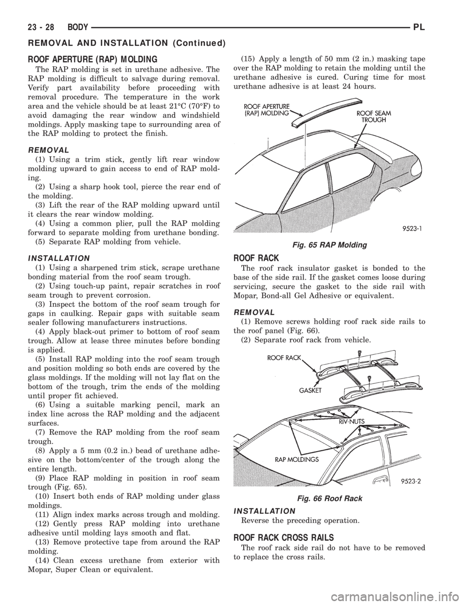
trough (Fig. 65).
(10) Insert both ends of RAP molding under glass
moldings.
(11) Align index marks across trough and molding.
(12) Gently press RAP molding into urethane
adhesive until molding lays smooth and flat.
(13) Remove protective tape from around the RAP
molding.
(14) Clean excess urethane from exterior with
Mopar, Super Clean or equivalent.(15) Apply a length of 50 mm (2 in.) masking tape
over the RAP molding to retain the molding until the
urethane adhesive is cured. Curing time for most
urethane adhesive is at least 24 hours.
ROOF RACK
The roof rack insulator gasket is bonded to the
base of the side rail. If the gasket comes loose during
servicing, secure the gasket to the side rail with
Mopar, Bond-all Gel Adhesive or equivalent.
REMOVAL
(1) Remove screws holding roof rack side rails to
the roof panel (Fig. 66).
(2) Separate roof rack from vehicle.
INSTALLATION
Reverse the preceding operation.
ROOF RACK CROSS RAILS
The roof rack side rail do not have to be removed
to replace the cross rails.
Fig. 65 RAP Molding
Fig. 66 Roof Rack
23 - 28 BODYPL
REMOVAL AND INSTALLATION (Continued)
Page 1110 of 1200
REMOVAL
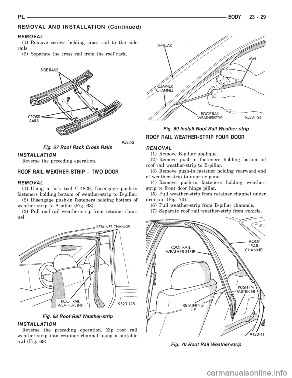
(1) Remove screws holding cross rail to the side
rails.
(2) Separate the cross rail from the roof rack.
INSTALLATION
Reverse the preceding operation.
ROOF RAIL WEATHER-STRIP ± TWO DOOR
REMOVAL
(1) Using a fork tool C-4829, Disengage push-in
fasteners holding bottom of weather-strip to B-pillar.
(2) Disengage push-in fasteners holding bottom of
weather-strip to A-pillar (Fig. 68).
(3) Pull roof rail weather-strip from retainer chan-
nel.
INSTALLATION
Reverse the preceding operation. Zip roof rail
weather-strip into retainer channel using a suitable
awl (Fig. 69).
ROOF RAIL WEATHER-STRIP FOUR DOOR
REMOVAL
(1) Remove B-pillar applique.
(2) Remove push-in fasteners holding bottom of
roof rail weather-strip to B-pillar.
(3) Remove push-in fastener holding rearward end
of weather-strip to quarter panel.
(4) Remove push-in fasteners holding weather-
strip to front door hinge pillar.
(5) Pull weather-strip from retainer channel under
drip rail (Fig. 70).
(6) Pull weather-strip from B-pillar channels.
(7) Separate roof rail weather-strip from vehicle.
Fig. 67 Roof Rack Cross Rails
Fig. 68 Roof Rail Weather-strip
Fig. 69 Install Roof Rail Weather-strip
Fig. 70 Roof Rail Weather-strip
PLBODY 23 - 29
REMOVAL AND INSTALLATION (Continued)
Page 1129 of 1200
SYMPTOM POSSIBLE CAUSE
Wind noise from sunroof.²Front of glass panel too high or rear too low.
²Glass panel not centered in opening.
²Faulty glass panel seal.
Glass panel hangs up or snaps between
vent and open.²Glass panel improperly adjusted.
²Glass panel seal has inconsistent compression.
Rattles from open sunroof while driving²Loose attaching hardware.
²Weak springs on wind deflector.
²Sunshade out of the track.
Rattles from closed sunroof while driving²Loose attaching hardware.
²Wind deflector contacting glass panel or drain trough.
²Sunshade out of the track.
REMOVAL AND INSTALLATION
SUNROOF PROCEDURE INFORMATION
The numbered call-outs in the following ser-
vice procedures refer the numbered parts
found in the figure at the end of this section.
SUNROOF CABLES
REMOVAL
(1) Remove sunroof glass panel (4). Refer to proce-
dure found in this section.
(2) Cycle the sunroof mechanism to the full for-
ward position.
CAUTION: Do not remove sunroof drive motor
unless sunroof mechanism is in the full forward
position.
(3) Remove sunroof drive motor (10). Refer to pro-
cedure found in this section.
(4) Remove front locator (7 or 8) for appropriate
sunroof cable.
(5) Disengage sunroof cable from sunroof mecha-
nism (9).
(6) Pull sunroof cable from drive tube (2 or 3).
INSTALLATION
(1) Push sunroof cable through drive tube (2 or 3).(2) Engage sunroof cable into sunroof mechanism
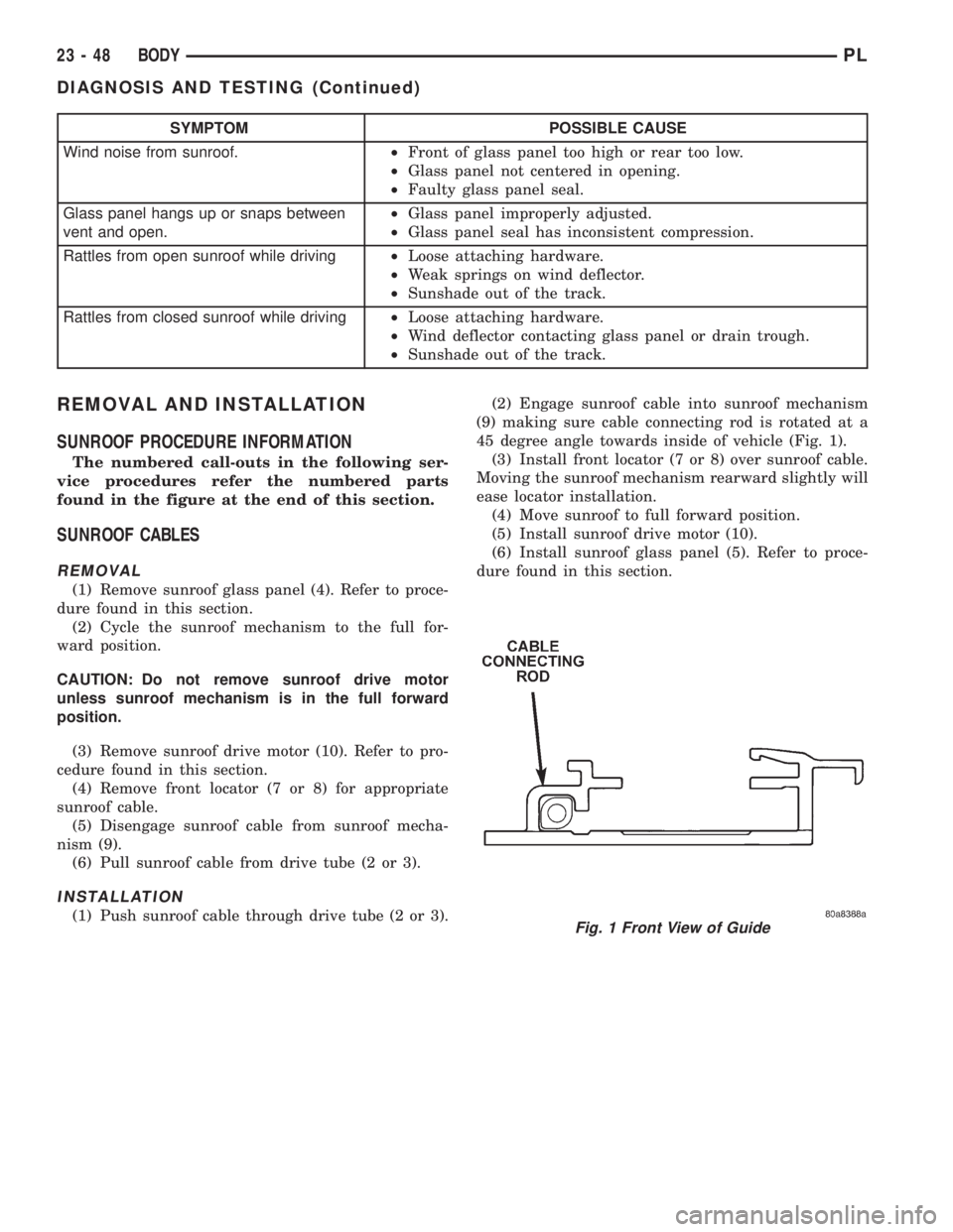
(9) making sure cable connecting rod is rotated at a
45 degree angle towards inside of vehicle (Fig. 1).
(3) Install front locator (7 or 8) over sunroof cable.
Moving the sunroof mechanism rearward slightly will
ease locator installation.
(4) Move sunroof to full forward position.
(5) Install sunroof drive motor (10).
(6) Install sunroof glass panel (5). Refer to proce-
dure found in this section.Fig. 1 Front View of Guide
23 - 48 BODYPL
DIAGNOSIS AND TESTING (Continued)
Page 1130 of 1200
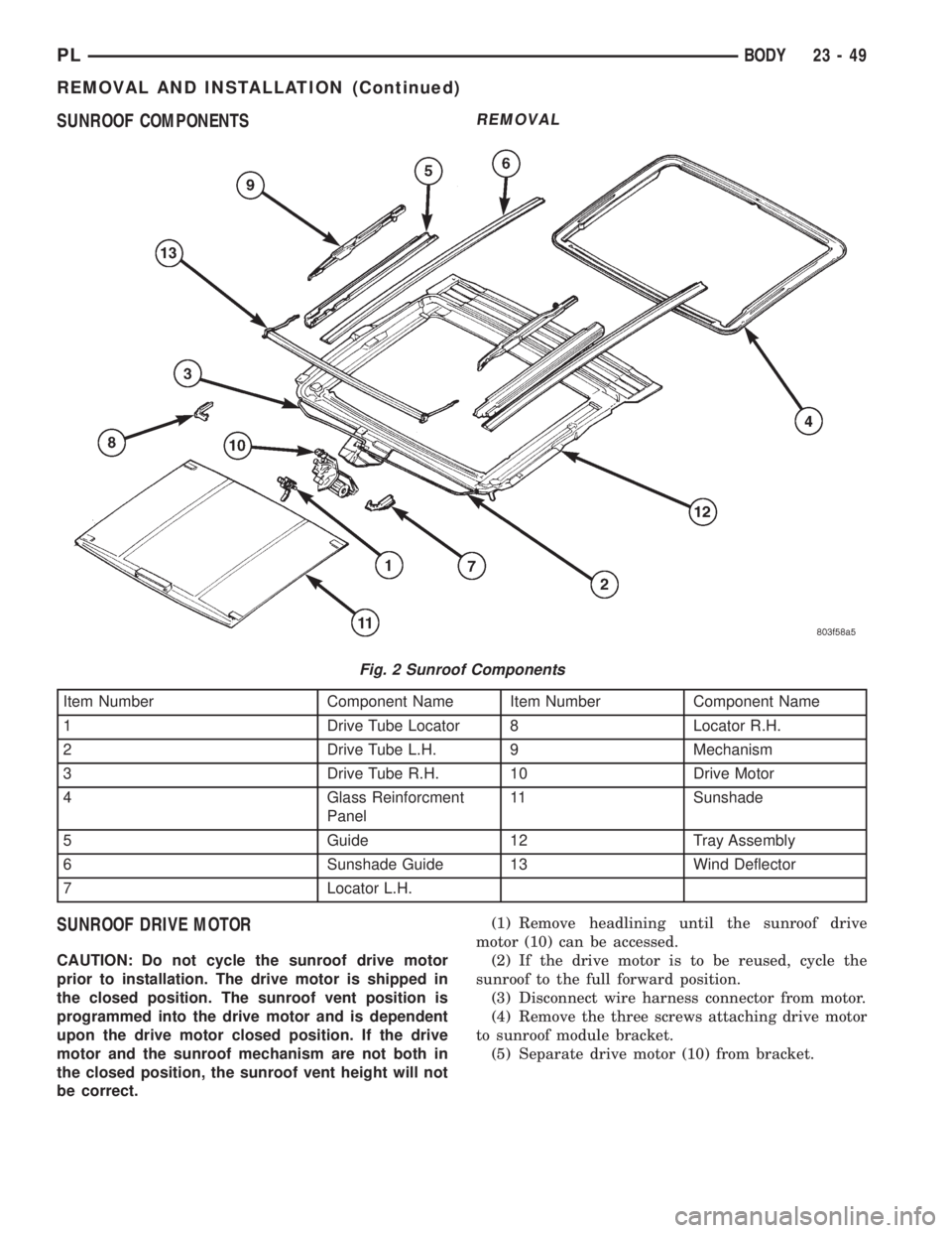
SUNROOF COMPONENTS
SUNROOF DRIVE MOTOR
CAUTION: Do not cycle the sunroof drive motor
prior to installation. The drive motor is shipped in
the closed position. The sunroof vent position is
programmed into the drive motor and is dependent
upon the drive motor closed position. If the drive
motor and the sunroof mechanism are not both in
the closed position, the sunroof vent height will not
be correct.
REMOVAL
(1) Remove headlining until the sunroof drive
motor (10) can be accessed.
(2) If the drive motor is to be reused, cycle the
sunroof to the full forward position.
(3) Disconnect wire harness connector from motor.
(4) Remove the three screws attaching drive motor
to sunroof module bracket.
(5) Separate drive motor (10) from bracket.
Fig. 2 Sunroof Components
Item Number Component Name Item Number Component Name
1 Drive Tube Locator 8 Locator R.H.
2 Drive Tube L.H. 9 Mechanism
3 Drive Tube R.H. 10 Drive Motor
4 Glass Reinforcment
Panel11 Sunshade
5 Guide 12 Tray Assembly
6 Sunshade Guide 13 Wind Deflector
7 Locator L.H.
PLBODY 23 - 49
REMOVAL AND INSTALLATION (Continued)
Page 1131 of 1200
INSTALLATION
(1) With the aid of a helper, hold the sunroof glass
panel in the closed position and engage the drive
motor (10) into the sunroof drive cables.
(2) Install screws holding drive motor to bracket.
(3) Connect wire harness to drive motor.
(4) Install headlining.
SUNROOF GLASS PANEL
REMOVAL
(1) Position sunroof sunshade (4) in full rearward
position.
(2) Remove six glass attachment screws.
(3) Push glass panel upward from underside until
glass panel clears the roof panel.
(4) Lift glass panel from vehicle.
INSTALLATION
(1) Position glass panel (4) in opening in vehicle
roof.
(2) Install, but do not tighten, glass attachment
screws.
(3) With the aid of a helper, hold the glass panel in
position and tighten glass attachment screws.
(4) Verify the correct glass height. Refer to Glass
Height Adjustment procedure in this section.
SUNROOF GUIDE AND MECHANISM ASSEMBLY
REMOVAL
(1) Remove sunroof glass panel (4). Refer to proce-
dure in this section.
(2) Remove front locator (7 or 8).
(3) Disengage cable from mechanism (9).
(4) Remove screws holding sunroof guide (5) and
mechanism (9) assembly to sunroof module.
(5) Lift assembly from module.
(6) Rotate assembly to disengage wind deflector
(13) from assembly.
INSTALLATION
(1) Engage wind deflector (13) into guide (5) and
mechanism (9) assembly.
(2) Position assembly onto module and install
screws holding assembly to sunroof module.
(3) Engage drive cable to mechanism.
(4) Install front locator (7 or 8 ). It may ease
installation to move sunroof mechanism slightly rear-
ward.
(5) Install sunroof glass panel. Refer to procedure
found in this section.
SUNROOF MODULE
REMOVAL
(1) Remove headlining.
(2) Remove fasteners attaching sunroof module to
vehicle roof and support braces.
(3) With the aid of a helper, separate sunroof mod-
ule from roof.
(4) Remove sunroof module from vehicle.
INSTALLATION
(1) With the aid of a helper, position sunroof mod-
ule in vehicle.
(2) Install fasteners holding sunroof module to
vehicle roof.
(3) Tighten all fasteners, starting from the front
and working rearward and then the motor bracket.
(4) Adjust glass panel for flushness to roof. Refer
to glass adjustment procedure in this section.
(5) Install headlining.
(6) Verify correct operation.
SUNROOF SUNSHADE
REMOVAL
(1) Remove sunroof glass panel (4). Refer to proce-
dure found in this section.
(2) Slide sunshade (11) to full forward position.
(3) Disengage slide blocks on one side of sunshade
from sunshade guide (6).
(4) Lift and pull sunshade out of opposite sun-
shade guide.
INSTALLATION
(1) Place sunshade with cloth side down and
install one side's slide blocks into the track on the
sunshade guide (6).
(2) Slide the other side's slide blocks to fully
inward position and insert them into the sunshade
guide (6).
(3) Verify that all four slide blocks are fully
engaged in the sunshade guide (6).
(4) Slide sunshade (11) fully rearward.
(5) Install sunroof glass panel (4). Refer to proce-
dure found in this section.
SUNROOF WIND DEFLECTOR
REMOVAL
(1) Open sunroof to full open position.
(2) Pull one end of wind deflector flap out of the
wind deflector beam (13).
(3) Release corner piece locking tab and separate
corner piece from wind deflector beam.
(4) Rotate corner piece outboard to release tab
from roof flange.
23 - 50 BODYPL
REMOVAL AND INSTALLATION (Continued)