door lock DODGE NEON 1999 Service Repair Manual
[x] Cancel search | Manufacturer: DODGE, Model Year: 1999, Model line: NEON, Model: DODGE NEON 1999Pages: 1200, PDF Size: 35.29 MB
Page 132 of 1200
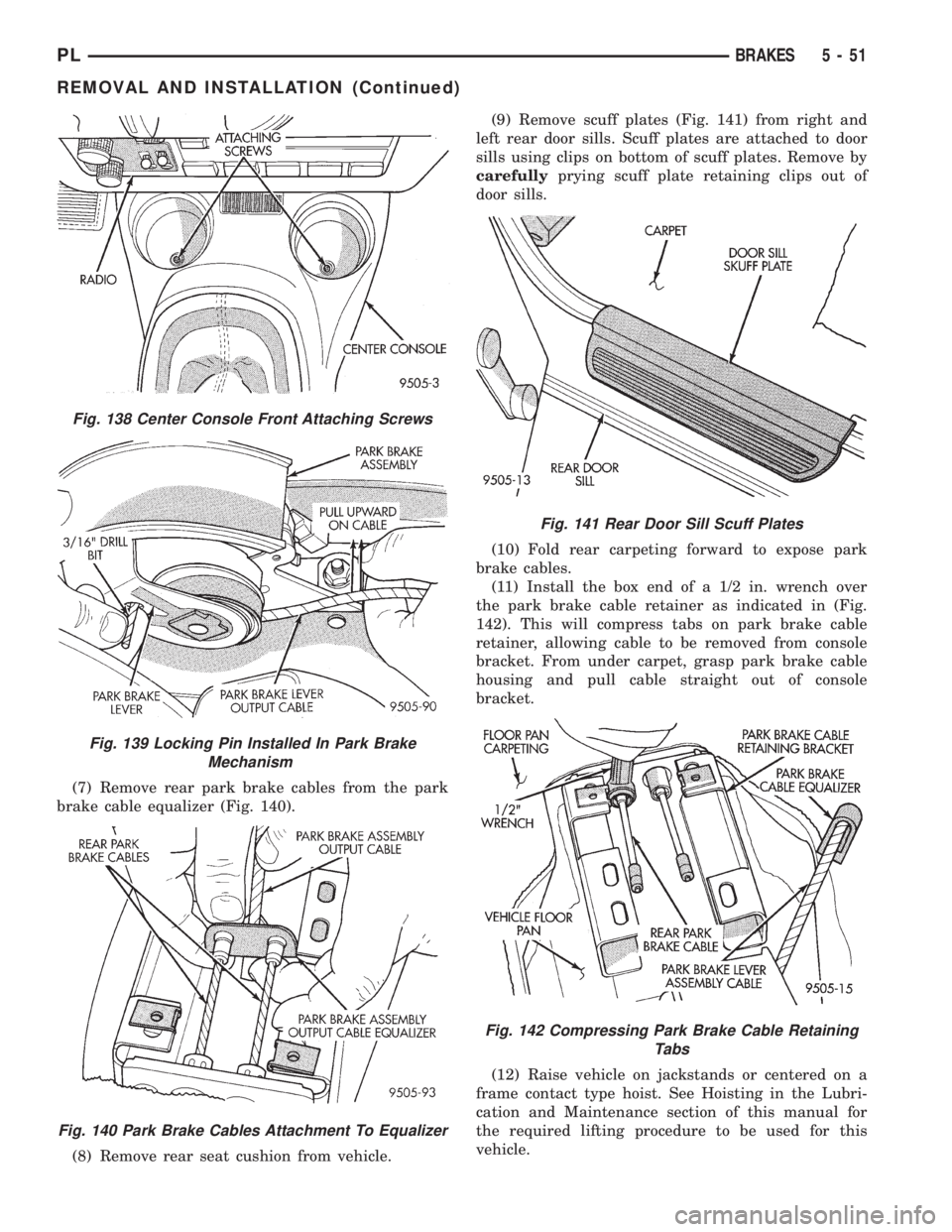
(7) Remove rear park brake cables from the park
brake cable equalizer (Fig. 140).
(8) Remove rear seat cushion from vehicle.(9) Remove scuff plates (Fig. 141) from right and
left rear door sills. Scuff plates are attached to door
sills using clips on bottom of scuff plates. Remove by
carefullyprying scuff plate retaining clips out of
door sills.
(10) Fold rear carpeting forward to expose park
brake cables.
(11) Install the box end of a 1/2 in. wrench over
the park brake cable retainer as indicated in (Fig.
142). This will compress tabs on park brake cable
retainer, allowing cable to be removed from console
bracket. From under carpet, grasp park brake cable
housing and pull cable straight out of console
bracket.
(12) Raise vehicle on jackstands or centered on a
frame contact type hoist. See Hoisting in the Lubri-
cation and Maintenance section of this manual for
the required lifting procedure to be used for this
vehicle.
Fig. 138 Center Console Front Attaching Screws
Fig. 139 Locking Pin Installed In Park Brake
Mechanism
Fig. 140 Park Brake Cables Attachment To Equalizer
Fig. 141 Rear Door Sill Scuff Plates
Fig. 142 Compressing Park Brake Cable Retaining
Tabs
PLBRAKES 5 - 51
REMOVAL AND INSTALLATION (Continued)
Page 136 of 1200
to one-half specified torque. Then repeat pattern,
fully tightening stud nuts to 135 N´m (100 ft. lbs.).
(11) Lower vehicle.
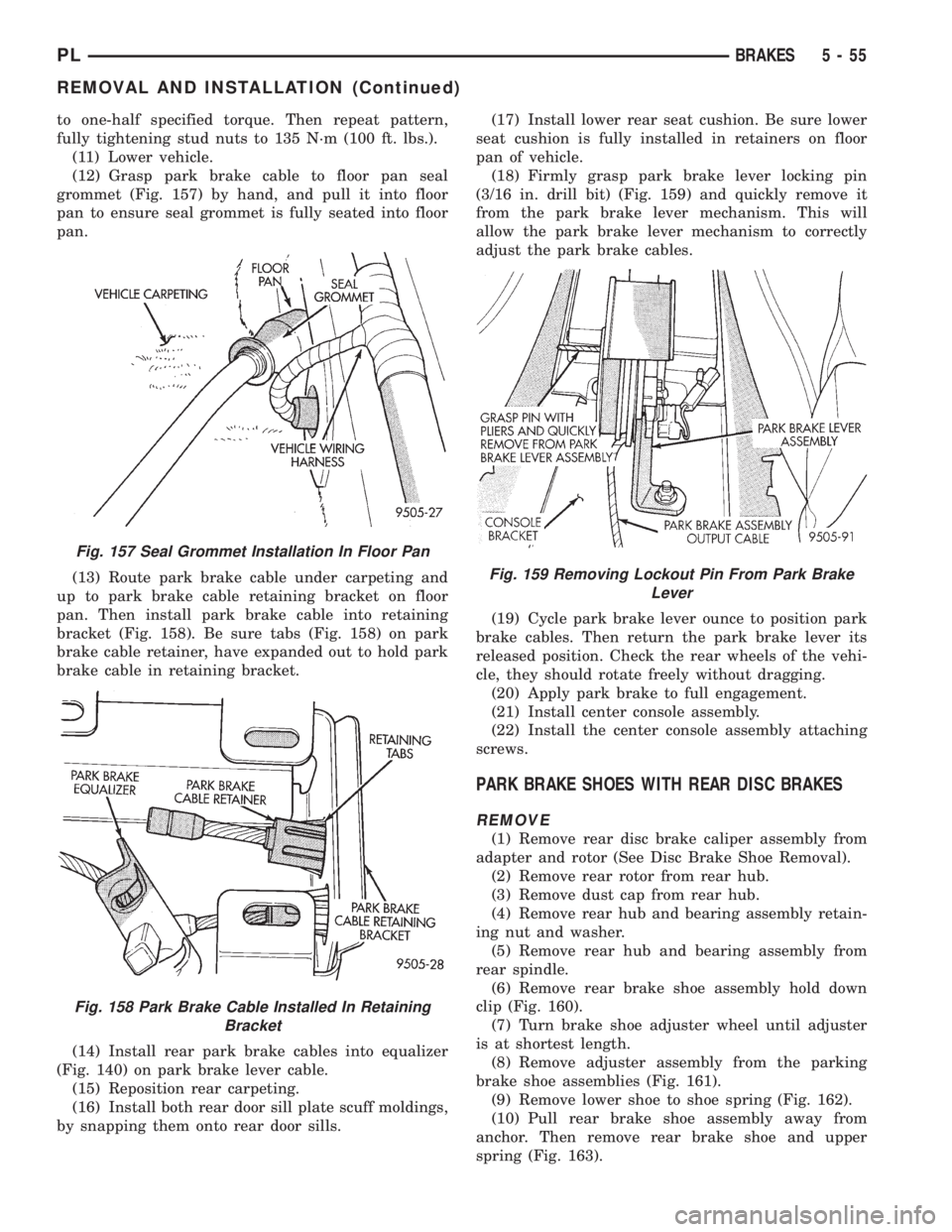
(12) Grasp park brake cable to floor pan seal
grommet (Fig. 157) by hand, and pull it into floor
pan to ensure seal grommet is fully seated into floor
pan.
(13) Route park brake cable under carpeting and
up to park brake cable retaining bracket on floor
pan. Then install park brake cable into retaining
bracket (Fig. 158). Be sure tabs (Fig. 158) on park
brake cable retainer, have expanded out to hold park
brake cable in retaining bracket.
(14) Install rear park brake cables into equalizer
(Fig. 140) on park brake lever cable.
(15) Reposition rear carpeting.
(16) Install both rear door sill plate scuff moldings,
by snapping them onto rear door sills.(17) Install lower rear seat cushion. Be sure lower
seat cushion is fully installed in retainers on floor
pan of vehicle.
(18) Firmly grasp park brake lever locking pin
(3/16 in. drill bit) (Fig. 159) and quickly remove it
from the park brake lever mechanism. This will
allow the park brake lever mechanism to correctly
adjust the park brake cables.
(19) Cycle park brake lever ounce to position park
brake cables. Then return the park brake lever its
released position. Check the rear wheels of the vehi-
cle, they should rotate freely without dragging.
(20) Apply park brake to full engagement.
(21) Install center console assembly.
(22) Install the center console assembly attaching
screws.
PARK BRAKE SHOES WITH REAR DISC BRAKES
REMOVE
(1) Remove rear disc brake caliper assembly from
adapter and rotor (See Disc Brake Shoe Removal).
(2) Remove rear rotor from rear hub.
(3) Remove dust cap from rear hub.
(4) Remove rear hub and bearing assembly retain-
ing nut and washer.
(5) Remove rear hub and bearing assembly from
rear spindle.
(6) Remove rear brake shoe assembly hold down
clip (Fig. 160).
(7) Turn brake shoe adjuster wheel until adjuster
is at shortest length.
(8) Remove adjuster assembly from the parking
brake shoe assemblies (Fig. 161).
(9) Remove lower shoe to shoe spring (Fig. 162).
(10) Pull rear brake shoe assembly away from
anchor. Then remove rear brake shoe and upper
spring (Fig. 163).
Fig. 157 Seal Grommet Installation In Floor Pan
Fig. 158 Park Brake Cable Installed In Retaining
Bracket
Fig. 159 Removing Lockout Pin From Park Brake
Lever
PLBRAKES 5 - 55
REMOVAL AND INSTALLATION (Continued)
Page 214 of 1200
must be replaced withonlythe recommended part
for adequate strength, performance and safety.
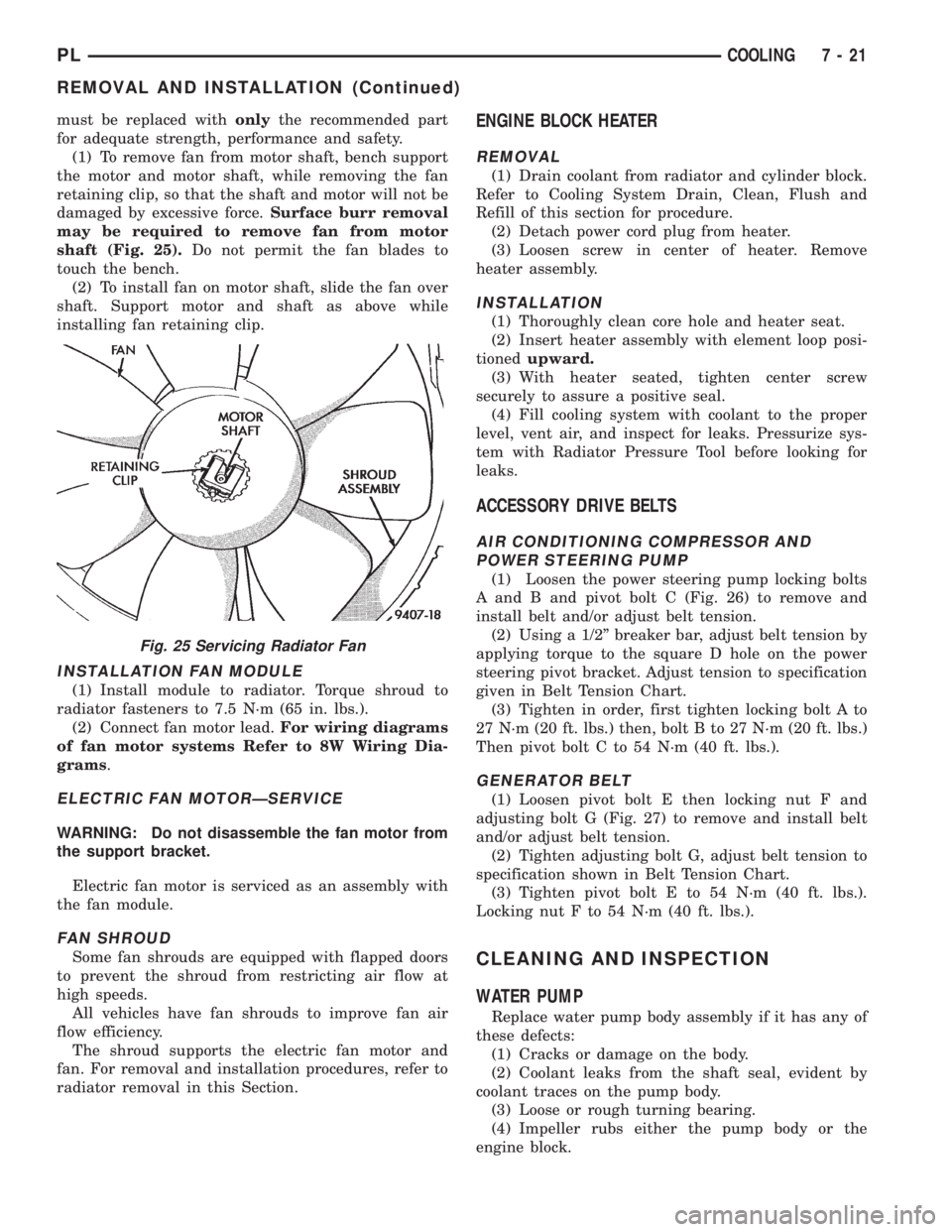
(1) To remove fan from motor shaft, bench support
the motor and motor shaft, while removing the fan
retaining clip, so that the shaft and motor will not be
damaged by excessive force.Surface burr removal
may be required to remove fan from motor
shaft (Fig. 25).Do not permit the fan blades to
touch the bench.
(2) To install fan on motor shaft, slide the fan over
shaft. Support motor and shaft as above while
installing fan retaining clip.
INSTALLATION FAN MODULE
(1) Install module to radiator. Torque shroud to
radiator fasteners to 7.5 N´m (65 in. lbs.).
(2) Connect fan motor lead.For wiring diagrams
of fan motor systems Refer to 8W Wiring Dia-
grams.
ELECTRIC FAN MOTORÐSERVICE
WARNING: Do not disassemble the fan motor from
the support bracket.
Electric fan motor is serviced as an assembly with
the fan module.
FAN SHROUD
Some fan shrouds are equipped with flapped doors
to prevent the shroud from restricting air flow at
high speeds.
All vehicles have fan shrouds to improve fan air
flow efficiency.
The shroud supports the electric fan motor and
fan. For removal and installation procedures, refer to
radiator removal in this Section.
ENGINE BLOCK HEATER
REMOVAL
(1) Drain coolant from radiator and cylinder block.
Refer to Cooling System Drain, Clean, Flush and
Refill of this section for procedure.
(2) Detach power cord plug from heater.
(3) Loosen screw in center of heater. Remove
heater assembly.
INSTALLATION
(1) Thoroughly clean core hole and heater seat.
(2) Insert heater assembly with element loop posi-
tionedupward.
(3) With heater seated, tighten center screw
securely to assure a positive seal.
(4) Fill cooling system with coolant to the proper
level, vent air, and inspect for leaks. Pressurize sys-
tem with Radiator Pressure Tool before looking for
leaks.
ACCESSORY DRIVE BELTS
AIR CONDITIONING COMPRESSOR AND
POWER STEERING PUMP
(1) Loosen the power steering pump locking bolts
A and B and pivot bolt C (Fig. 26) to remove and
install belt and/or adjust belt tension.
(2) Using a 1/2º breaker bar, adjust belt tension by
applying torque to the square D hole on the power
steering pivot bracket. Adjust tension to specification
given in Belt Tension Chart.
(3) Tighten in order, first tighten locking bolt A to
27 N´m (20 ft. lbs.) then, bolt B to 27 N´m (20 ft. lbs.)
Then pivot bolt C to 54 N´m (40 ft. lbs.).
GENERATOR BELT
(1) Loosen pivot bolt E then locking nut F and
adjusting bolt G (Fig. 27) to remove and install belt
and/or adjust belt tension.
(2) Tighten adjusting bolt G, adjust belt tension to
specification shown in Belt Tension Chart.
(3) Tighten pivot bolt E to 54 N´m (40 ft. lbs.).
Locking nut F to 54 N´m (40 ft. lbs.).
CLEANING AND INSPECTION
WATER PUMP
Replace water pump body assembly if it has any of
these defects:
(1) Cracks or damage on the body.
(2) Coolant leaks from the shaft seal, evident by
coolant traces on the pump body.
(3) Loose or rough turning bearing.
(4) Impeller rubs either the pump body or the
engine block.
Fig. 25 Servicing Radiator Fan
PLCOOLING 7 - 21
REMOVAL AND INSTALLATION (Continued)
Page 270 of 1200
INSTRUMENT PANEL AND SYSTEMS
CONTENTS
page page
GENERAL INFORMATION
INTRODUCTION......................... 1
DESCRIPTION AND OPERATION
DOME LAMP............................ 1
ELECTRONIC DIGITAL CLOCK.............. 1
INSTRUMENT CLUSTER................... 2
WARNING AND INDICATOR LAMPS......... 2
DIAGNOSIS AND TESTING
AIRBAG WARNING SYSTEM............... 2
BRAKE SYSTEM WARNING LAMP TEST...... 2
FOG LAMP SWITCH TEST................. 2
FUEL TANK SENDING UNIT TEST........... 3
HEADLAMP SWITCH TEST................. 3
HEATER A/C BLOWER SWITCH TEST........ 3
HEATER BLOWER SWITCH TEST............ 3
INDIVIDUAL GAUGE INOPERATIVE.......... 4
INSTRUMENT PANEL AND COMPONENTS.... 4
LOW OIL PRESSURE WARNING LAMP TEST . . 4
MULTIPLE GAUGE INOPERATIVE TEST....... 4
SEAT BELT REMINDER SYSTEM TEST....... 6
SENDING UNIT......................... 6
SERVICE ENGINE SOON INDICATOR......... 6
VEHICLE SPEED SENSOR TEST............. 6
REMOVAL AND INSTALLATION
ASH RECEIVER RETAINER AND LAMP....... 6
CENTER BEZEL.......................... 6
CIGAR LIGHTER RECEPTACLE.............. 6
CLUSTER LAMP......................... 7
CLUSTER PRINTED CIRCUIT BOARD........ 7CLUSTER.............................. 7
DOME LENS/LAMP....................... 8
FLOOR CONSOLE........................ 8
GAUGE................................ 8
GLOVE BOX DOOR/BIN................... 8
GLOVE BOX SWITCH/LAMP................ 9
HEADLAMP SWITCH..................... 9
HEATER A/C CONTROL BLOWER SWITCH . . . 10
HEATER A/C CONTROL LAMP............ 10
HEATER A/C CONTROL................... 9
HEATER CONTROL BLOWER SWITCH....... 10
IGNITION KEY LAMP.................... 10
INSTRUMENT PANEL.................... 10
LEFT TRIM PANEL...................... 10
ODOMETER............................ 10
RADIO................................ 12
REAR WINDOW DEFOGGER AND/OR FOG
LAMP SWITCH....................... 12
RIGHT TRIM PANEL..................... 12
SHIFTER KNOB......................... 13
STEERING COLUMN COVER LINER......... 13
STEERING COLUMN COVER.............. 13
STEERING COLUMN SHROUDS............ 13
TOP COVER AND CLUSTER BEZEL
REMOVAL........................... 14
TRANSMISSION RANGE INDICATOR LAMP . . 14
TRUNK LAMP/LENS..................... 14
VEHICLE SPEED SENSOR................ 14
GENERAL INFORMATION
INTRODUCTION
The purpose of the dash gauges and indicator
lamps is to keep the driver informed about the oper-
ating condition of the vehicle. If an abnormal condi-
tion occurs, the driver is informed by indicator lamp.
The driver can seek service before damage occurs.
Indicator lamps use ON/OFF switch functions for
operation, while gauges use a sending unit or sensor.
DESCRIPTION AND OPERATION
DOME LAMP
The Dome Lamp operates when a door is open or
when the headlamp switch is placed in courtesy posi-
tion.
ELECTRONIC DIGITAL CLOCK
The electronic digital clock is in the radio. The
clock and radio each use the display panel built into
the radio. A digital readout indicates the time in
hours and minutes whenever the ignition switch is in
the ON or ACC position.
PLINSTRUMENT PANEL AND SYSTEMS 8E - 1
Page 271 of 1200
When the ignition switch is in the OFF position, or
when the radio frequency is being displayed, time
keeping is accurately maintained.
The procedure for setting the clock varies slightly
with each radio. The correct procedure is described in
the individual radio operating instructions. Refer to
the Owner's Manual supplied with the vehicle.
INSTRUMENT CLUSTER
There are two conventional instrument cluster
assemblies available. The clusters electronically drive
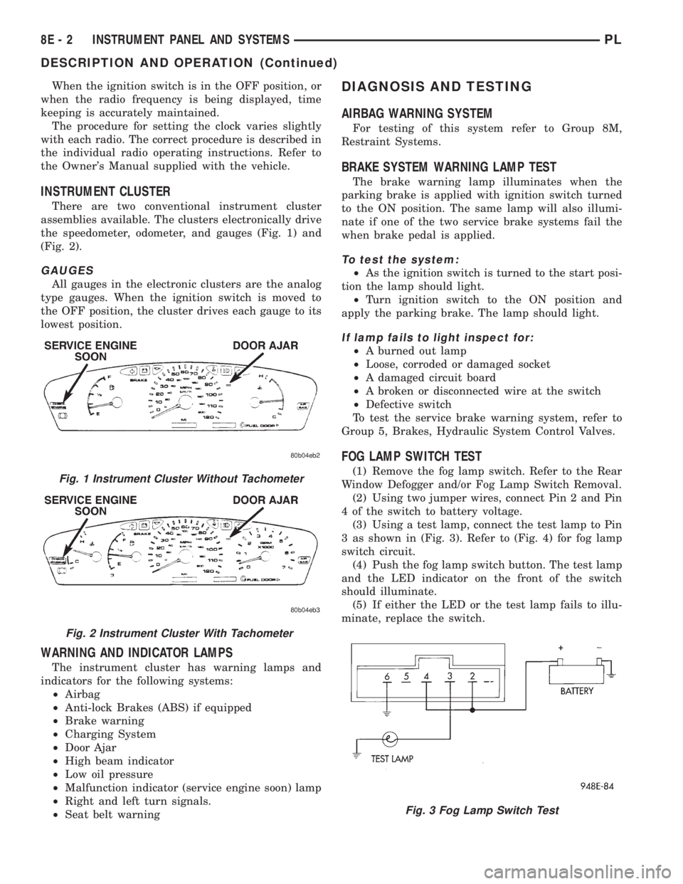
the speedometer, odometer, and gauges (Fig. 1) and
(Fig. 2).
GAUGES
All gauges in the electronic clusters are the analog
type gauges. When the ignition switch is moved to
the OFF position, the cluster drives each gauge to its
lowest position.
WARNING AND INDICATOR LAMPS
The instrument cluster has warning lamps and
indicators for the following systems:
²Airbag
²Anti-lock Brakes (ABS) if equipped
²Brake warning
²Charging System
²Door Ajar
²High beam indicator
²Low oil pressure
²Malfunction indicator (service engine soon) lamp
²Right and left turn signals.
²Seat belt warning
DIAGNOSIS AND TESTING
AIRBAG WARNING SYSTEM
For testing of this system refer to Group 8M,
Restraint Systems.
BRAKE SYSTEM WARNING LAMP TEST
The brake warning lamp illuminates when the
parking brake is applied with ignition switch turned
to the ON position. The same lamp will also illumi-
nate if one of the two service brake systems fail the
when brake pedal is applied.
To test the system:
²As the ignition switch is turned to the start posi-
tion the lamp should light.
²Turn ignition switch to the ON position and
apply the parking brake. The lamp should light.
If lamp fails to light inspect for:
²A burned out lamp
²Loose, corroded or damaged socket
²A damaged circuit board
²A broken or disconnected wire at the switch
²Defective switch
To test the service brake warning system, refer to
Group 5, Brakes, Hydraulic System Control Valves.
FOG LAMP SWITCH TEST
(1) Remove the fog lamp switch. Refer to the Rear
Window Defogger and/or Fog Lamp Switch Removal.
(2) Using two jumper wires, connect Pin 2 and Pin
4 of the switch to battery voltage.
(3) Using a test lamp, connect the test lamp to Pin
3 as shown in (Fig. 3). Refer to (Fig. 4) for fog lamp
switch circuit.
(4) Push the fog lamp switch button. The test lamp
and the LED indicator on the front of the switch
should illuminate.
(5) If either the LED or the test lamp fails to illu-
minate, replace the switch.Fig. 1 Instrument Cluster Without Tachometer
Fig. 2 Instrument Cluster With Tachometer
Fig. 3 Fog Lamp Switch Test
8E - 2 INSTRUMENT PANEL AND SYSTEMSPL
DESCRIPTION AND OPERATION (Continued)
Page 288 of 1200
AUDIO SYSTEM
CONTENTS
page page
GENERAL INFORMATION
INTRODUCTION......................... 1
DESCRIPTION AND OPERATION
INTERFERENCE ELIMINATION.............. 1
DIAGNOSIS AND TESTING
ANTENNA.............................. 3
AUDIO DIAGNOSTIC TEST PROCEDURES..... 1BENCH TEST FOR ANTENNA MALFUNCTION . . 3
REMOVAL AND INSTALLATION
ANTENNA.............................. 3
FRONT DOOR SPEAKER................... 4
INSTRUMENT PANEL SPEAKER............. 4
RADIO................................. 4
REAR SHELF SPEAKER(S)................. 5
GENERAL INFORMATION
INTRODUCTION
Operating instructions for the factory installed
audio systems can be found in the Owner's Manual
provided with the vehicle.
The vehicles are equipped with an Interior (Igni-
tion Off Draw) fuse in the Power Distribution Center
located in the engine compartment. After the Interior
(IOD) fuse or battery has been disconnected the clock
will require resetting.
DESCRIPTION AND OPERATION
INTERFERENCE ELIMINATION
The radio utilizes a ground wire plugged on to a
blade terminal and is bolted to the radio chassis.
Both connector and terminal should be securely
attached. The engine has three separate ground
straps to suppress ignition noise which may interfere
with radio reception.
²Left engine mount clip on strap
²Engine to shock tower reinforcement
²Rear strut to body, clip-on strap
Inductive type spark plug cables in the high ten-
sion circuit of the ignition system complete the inter-
ference suppression. Faulty or deteriorated spark
plug wires should be replaced.
In addition, there is a capacitor mounted on the
cylinder head which also helps suppress ignition
noise.
DIAGNOSIS AND TESTING
AUDIO DIAGNOSTIC TEST PROCEDURES
CAUTION: The CD player will only operate between
approximate temperatures of -23ÉC and +65ÉC (-10ÉF
and +145ÉF).
Whenever a radio malfunction occurs;
(1) First check FUSES:
(a) Power Distribution Center (PDC), Interior
lamp fuse, M1 - Radio Memory Feed
(b) Fuse Block:
(I) Fuse 12, Illumination in the fuse block
(II) Fuse 16, Ignition feed in the fuse block
NOTE: The vehicles are shipped with the INTERIOR
LAMP fuse disconnected.
(2) Verify, the radio wire harness are properly con-
nected before starting normal diagnosis and repair
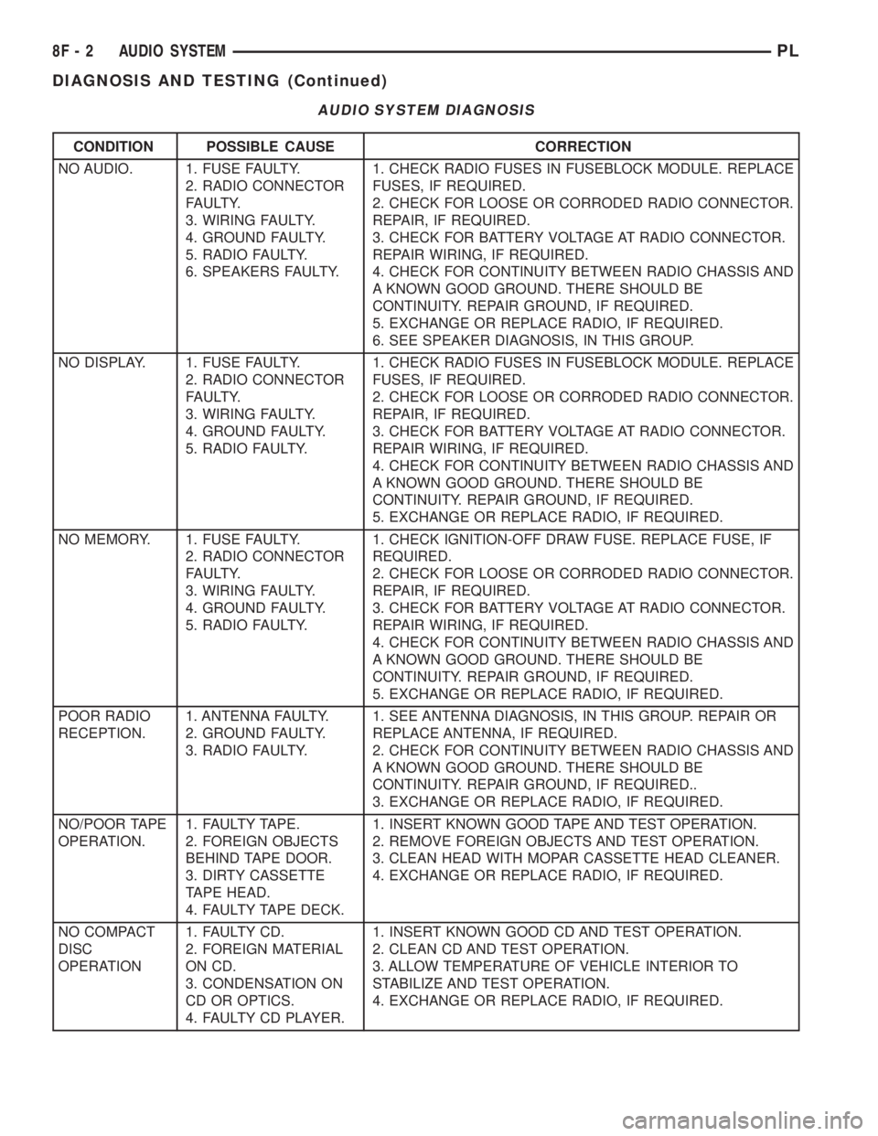
procedures. Refer to Audio Diagnosis table and/or
Group 8W, Wiring Diagrams, Radio Section.
PLAUDIO SYSTEM 8F - 1
Page 289 of 1200
AUDIO SYSTEM DIAGNOSIS
CONDITION POSSIBLE CAUSE CORRECTION
NO AUDIO. 1. FUSE FAULTY.
2. RADIO CONNECTOR
FAULTY.
3. WIRING FAULTY.
4. GROUND FAULTY.
5. RADIO FAULTY.
6. SPEAKERS FAULTY.1. CHECK RADIO FUSES IN FUSEBLOCK MODULE. REPLACE
FUSES, IF REQUIRED.
2. CHECK FOR LOOSE OR CORRODED RADIO CONNECTOR.
REPAIR, IF REQUIRED.
3. CHECK FOR BATTERY VOLTAGE AT RADIO CONNECTOR.
REPAIR WIRING, IF REQUIRED.
4. CHECK FOR CONTINUITY BETWEEN RADIO CHASSIS AND
A KNOWN GOOD GROUND. THERE SHOULD BE
CONTINUITY. REPAIR GROUND, IF REQUIRED.
5. EXCHANGE OR REPLACE RADIO, IF REQUIRED.
6. SEE SPEAKER DIAGNOSIS, IN THIS GROUP.
NO DISPLAY. 1. FUSE FAULTY.
2. RADIO CONNECTOR
FAULTY.
3. WIRING FAULTY.
4. GROUND FAULTY.
5. RADIO FAULTY.1. CHECK RADIO FUSES IN FUSEBLOCK MODULE. REPLACE
FUSES, IF REQUIRED.
2. CHECK FOR LOOSE OR CORRODED RADIO CONNECTOR.
REPAIR, IF REQUIRED.
3. CHECK FOR BATTERY VOLTAGE AT RADIO CONNECTOR.
REPAIR WIRING, IF REQUIRED.
4. CHECK FOR CONTINUITY BETWEEN RADIO CHASSIS AND
A KNOWN GOOD GROUND. THERE SHOULD BE
CONTINUITY. REPAIR GROUND, IF REQUIRED.
5. EXCHANGE OR REPLACE RADIO, IF REQUIRED.
NO MEMORY. 1. FUSE FAULTY.
2. RADIO CONNECTOR
FAULTY.
3. WIRING FAULTY.
4. GROUND FAULTY.
5. RADIO FAULTY.1. CHECK IGNITION-OFF DRAW FUSE. REPLACE FUSE, IF
REQUIRED.
2. CHECK FOR LOOSE OR CORRODED RADIO CONNECTOR.
REPAIR, IF REQUIRED.
3. CHECK FOR BATTERY VOLTAGE AT RADIO CONNECTOR.
REPAIR WIRING, IF REQUIRED.
4. CHECK FOR CONTINUITY BETWEEN RADIO CHASSIS AND
A KNOWN GOOD GROUND. THERE SHOULD BE
CONTINUITY. REPAIR GROUND, IF REQUIRED.
5. EXCHANGE OR REPLACE RADIO, IF REQUIRED.
POOR RADIO
RECEPTION.1. ANTENNA FAULTY.
2. GROUND FAULTY.
3. RADIO FAULTY.1. SEE ANTENNA DIAGNOSIS, IN THIS GROUP. REPAIR OR
REPLACE ANTENNA, IF REQUIRED.
2. CHECK FOR CONTINUITY BETWEEN RADIO CHASSIS AND
A KNOWN GOOD GROUND. THERE SHOULD BE
CONTINUITY. REPAIR GROUND, IF REQUIRED..
3. EXCHANGE OR REPLACE RADIO, IF REQUIRED.
NO/POOR TAPE
OPERATION.1. FAULTY TAPE.
2. FOREIGN OBJECTS
BEHIND TAPE DOOR.
3. DIRTY CASSETTE
TAPE HEAD.
4. FAULTY TAPE DECK.1. INSERT KNOWN GOOD TAPE AND TEST OPERATION.
2. REMOVE FOREIGN OBJECTS AND TEST OPERATION.
3. CLEAN HEAD WITH MOPAR CASSETTE HEAD CLEANER.
4. EXCHANGE OR REPLACE RADIO, IF REQUIRED.
NO COMPACT
DISC
OPERATION1. FAULTY CD.
2. FOREIGN MATERIAL
ON CD.
3. CONDENSATION ON
CD OR OPTICS.
4. FAULTY CD PLAYER.1. INSERT KNOWN GOOD CD AND TEST OPERATION.
2. CLEAN CD AND TEST OPERATION.
3. ALLOW TEMPERATURE OF VEHICLE INTERIOR TO
STABILIZE AND TEST OPERATION.
4. EXCHANGE OR REPLACE RADIO, IF REQUIRED.
8F - 2 AUDIO SYSTEMPL
DIAGNOSIS AND TESTING (Continued)
Page 354 of 1200
DIAGNOSIS AND TESTING
AIRBAG SYSTEM TEST
(1) Disconnect and isolate the negative battery
cable.
(2) Connect scan tool (DRB) to Data Link connec-
tor, located at right side of the steering column and
at the lower edge of the lower instrument panel.
(3) Turn the ignition key to ON position. Exit vehi-
cle with scan tool. Use the latest version of the
proper cartridge.
(4) After checking that no one is inside the vehicle,
connect the battery negative terminal.
(5) Using the scan tool, read and record active
diagnostic code data.
(6) Read and record any stored diagnostic codes.
(7) Refer to the Passive Restraint Diagnostic Test
Manual if any diagnostic codes are found in Step 5 or
Step 6.
(8) Erase stored diagnostic codes if there are no
active diagnostic codes. If problems remain, diagnos-
tic codes will not erase. Refer to the Passive
Restraint Diagnostic Test Manual to diagnose the
problem.If the airbag warning lamp either fails
to light with the ignition switch on, or the light
goes on and stays on, there is a system malfunc-
tion. Refer to the Passive Restraint Diagnostic
Test Manual to diagnose the problem.
SERVICE PROCEDURES
CLEANUP PROCEDURE
Roll or fold the passenger airbag towards the
instrument panel surface and close the door over the
folded bag. Then tape the door shut.
Use a vacuum cleaner to remove any residual pow-
der from the vehicle interior. Work from the outside
in to avoid kneeling or sitting in a contaminated
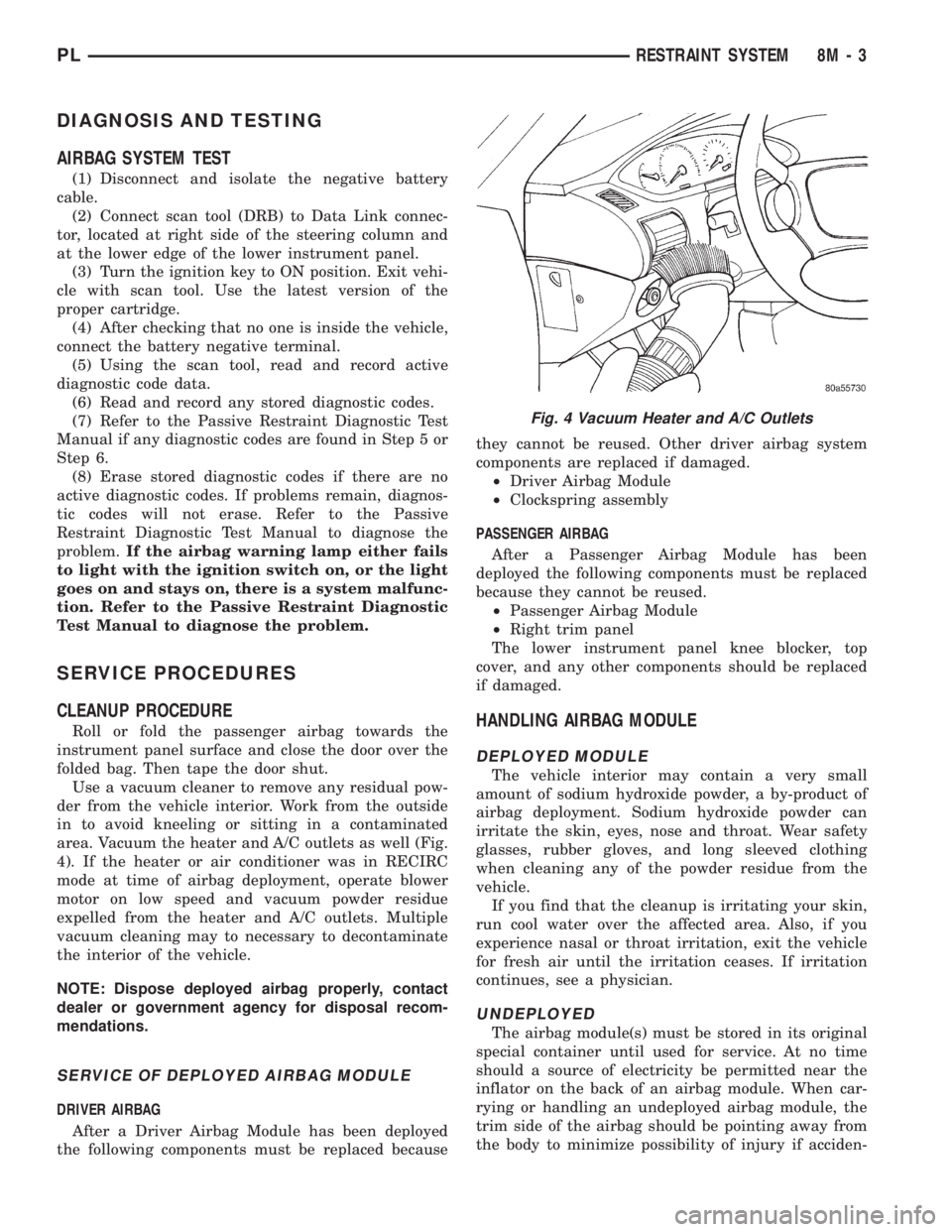
area. Vacuum the heater and A/C outlets as well (Fig.
4). If the heater or air conditioner was in RECIRC
mode at time of airbag deployment, operate blower
motor on low speed and vacuum powder residue
expelled from the heater and A/C outlets. Multiple
vacuum cleaning may to necessary to decontaminate
the interior of the vehicle.
NOTE: Dispose deployed airbag properly, contact
dealer or government agency for disposal recom-
mendations.
SERVICE OF DEPLOYED AIRBAG MODULE
DRIVER AIRBAG
After a Driver Airbag Module has been deployed
the following components must be replaced becausethey cannot be reused. Other driver airbag system
components are replaced if damaged.
²Driver Airbag Module
²Clockspring assembly
PASSENGER AIRBAG
After a Passenger Airbag Module has been
deployed the following components must be replaced
because they cannot be reused.
²Passenger Airbag Module
²Right trim panel
The lower instrument panel knee blocker, top
cover, and any other components should be replaced
if damaged.
HANDLING AIRBAG MODULE
DEPLOYED MODULE
The vehicle interior may contain a very small
amount of sodium hydroxide powder, a by-product of
airbag deployment. Sodium hydroxide powder can
irritate the skin, eyes, nose and throat. Wear safety
glasses, rubber gloves, and long sleeved clothing
when cleaning any of the powder residue from the
vehicle.
If you find that the cleanup is irritating your skin,
run cool water over the affected area. Also, if you
experience nasal or throat irritation, exit the vehicle
for fresh air until the irritation ceases. If irritation
continues, see a physician.
UNDEPLOYED
The airbag module(s) must be stored in its original
special container until used for service. At no time
should a source of electricity be permitted near the
inflator on the back of an airbag module. When car-
rying or handling an undeployed airbag module, the
trim side of the airbag should be pointing away from
the body to minimize possibility of injury if acciden-
Fig. 4 Vacuum Heater and A/C Outlets
PLRESTRAINT SYSTEM 8M - 3
Page 360 of 1200
DRIVER AIRBAG MODULE
REMOVAL
WARNING: DISCONNECT AND ISOLATE THE BAT-
TERY NEGATIVE (GROUND) CABLE BEFORE
BEGINNING ANY AIRBAG SYSTEM COMPONENT
REMOVAL OR INSTALLATION PROCEDURE. THIS
WILL DISABLE THE AIRBAG SYSTEM. FAILURE TO
DISCONNECT BATTERY COULD RESULT IN ACCI-
DENTAL AIRBAG DEPLOYMENT AND POSSIBLE
PERSONAL INJURY. ALLOW SYSTEM CAPACITOR
TO DISCHARGE FOR 2 MINUTES BEFORE REMOV-
ING ANY AIRBAG COMPONENTS.
When removing a deployed module, rubber gloves,
eye protection and long sleeved shirt should be worn,
as there may be deposits on the surface which could
irritate the skin and eyes.
(1) Disconnect and isolate the battery negative
cable.
(2) Remove speed control switches or covers from
steering wheel armature and disconnect the wires.
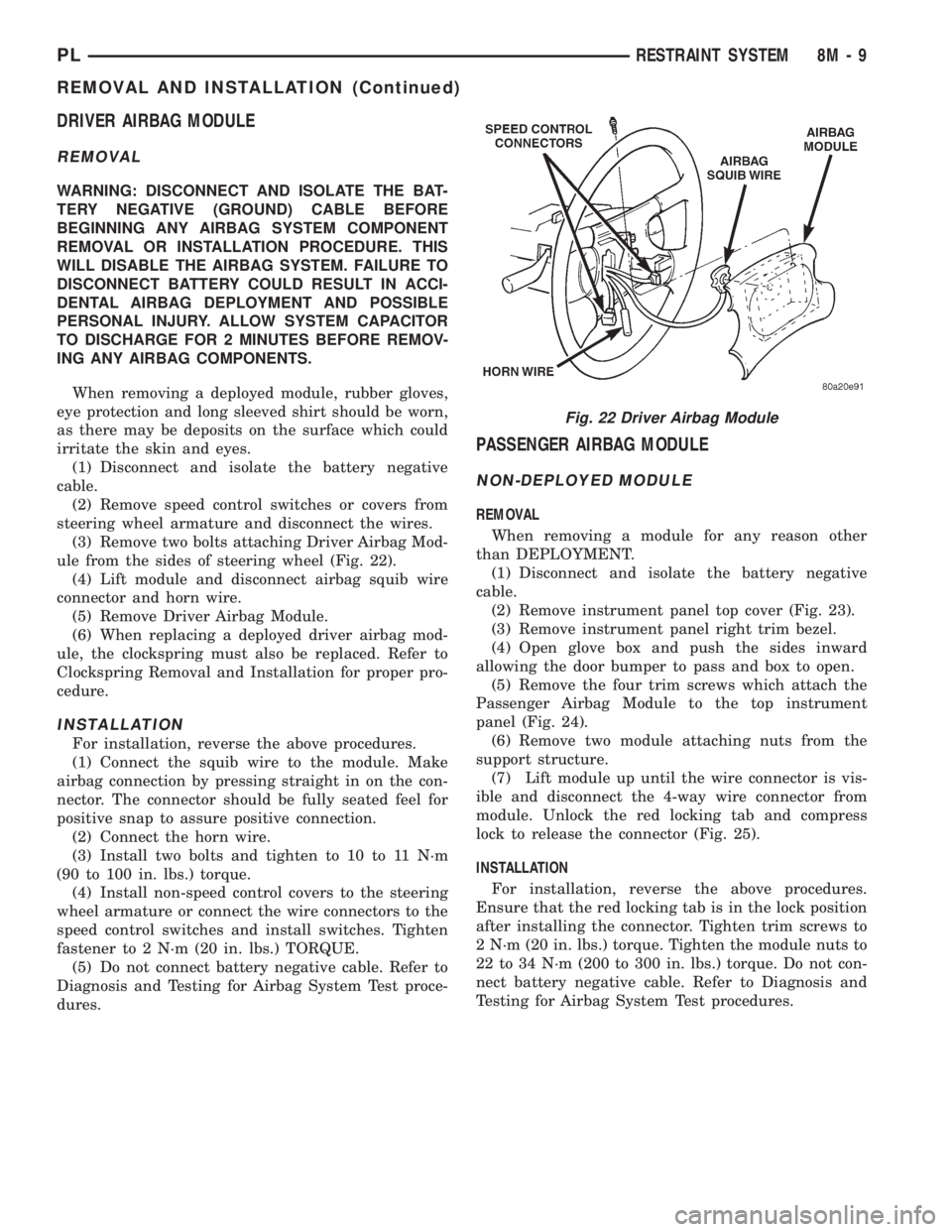
(3) Remove two bolts attaching Driver Airbag Mod-
ule from the sides of steering wheel (Fig. 22).
(4) Lift module and disconnect airbag squib wire
connector and horn wire.
(5) Remove Driver Airbag Module.
(6) When replacing a deployed driver airbag mod-
ule, the clockspring must also be replaced. Refer to
Clockspring Removal and Installation for proper pro-
cedure.
INSTALLATION
For installation, reverse the above procedures.
(1) Connect the squib wire to the module. Make
airbag connection by pressing straight in on the con-
nector. The connector should be fully seated feel for
positive snap to assure positive connection.
(2) Connect the horn wire.
(3) Install two bolts and tighten to 10 to 11 N´m
(90 to 100 in. lbs.) torque.
(4) Install non-speed control covers to the steering
wheel armature or connect the wire connectors to the
speed control switches and install switches. Tighten
fastener to 2 N´m (20 in. lbs.) TORQUE.
(5) Do not connect battery negative cable. Refer to
Diagnosis and Testing for Airbag System Test proce-
dures.
PASSENGER AIRBAG MODULE
NON-DEPLOYED MODULE
REMOVAL
When removing a module for any reason other
than DEPLOYMENT.
(1) Disconnect and isolate the battery negative
cable.
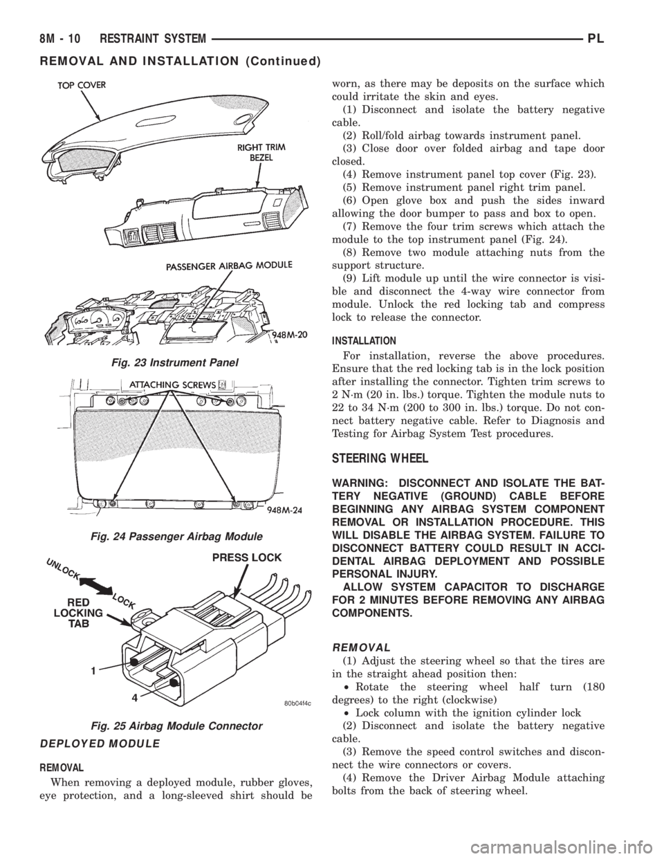
(2) Remove instrument panel top cover (Fig. 23).
(3) Remove instrument panel right trim bezel.
(4) Open glove box and push the sides inward
allowing the door bumper to pass and box to open.
(5) Remove the four trim screws which attach the
Passenger Airbag Module to the top instrument
panel (Fig. 24).
(6) Remove two module attaching nuts from the
support structure.
(7) Lift module up until the wire connector is vis-
ible and disconnect the 4-way wire connector from
module. Unlock the red locking tab and compress
lock to release the connector (Fig. 25).
INSTALLATION
For installation, reverse the above procedures.
Ensure that the red locking tab is in the lock position
after installing the connector. Tighten trim screws to
2 N´m (20 in. lbs.) torque. Tighten the module nuts to
22 to 34 N´m (200 to 300 in. lbs.) torque. Do not con-
nect battery negative cable. Refer to Diagnosis and
Testing for Airbag System Test procedures.
Fig. 22 Driver Airbag Module
PLRESTRAINT SYSTEM 8M - 9
REMOVAL AND INSTALLATION (Continued)
Page 361 of 1200
DEPLOYED MODULE
REMOVAL
When removing a deployed module, rubber gloves,
eye protection, and a long-sleeved shirt should beworn, as there may be deposits on the surface which
could irritate the skin and eyes.
(1) Disconnect and isolate the battery negative
cable.
(2) Roll/fold airbag towards instrument panel.
(3) Close door over folded airbag and tape door
closed.
(4) Remove instrument panel top cover (Fig. 23).
(5) Remove instrument panel right trim panel.
(6) Open glove box and push the sides inward
allowing the door bumper to pass and box to open.
(7) Remove the four trim screws which attach the
module to the top instrument panel (Fig. 24).
(8) Remove two module attaching nuts from the
support structure.
(9) Lift module up until the wire connector is visi-
ble and disconnect the 4-way wire connector from
module. Unlock the red locking tab and compress
lock to release the connector.
INSTALLATION
For installation, reverse the above procedures.
Ensure that the red locking tab is in the lock position
after installing the connector. Tighten trim screws to
2 N´m (20 in. lbs.) torque. Tighten the module nuts to
22 to 34 N´m (200 to 300 in. lbs.) torque. Do not con-
nect battery negative cable. Refer to Diagnosis and
Testing for Airbag System Test procedures.
STEERING WHEEL
WARNING: DISCONNECT AND ISOLATE THE BAT-
TERY NEGATIVE (GROUND) CABLE BEFORE
BEGINNING ANY AIRBAG SYSTEM COMPONENT
REMOVAL OR INSTALLATION PROCEDURE. THIS
WILL DISABLE THE AIRBAG SYSTEM. FAILURE TO
DISCONNECT BATTERY COULD RESULT IN ACCI-
DENTAL AIRBAG DEPLOYMENT AND POSSIBLE
PERSONAL INJURY.
ALLOW SYSTEM CAPACITOR TO DISCHARGE
FOR 2 MINUTES BEFORE REMOVING ANY AIRBAG
COMPONENTS.
REMOVAL
(1) Adjust the steering wheel so that the tires are
in the straight ahead position then:
²Rotate the steering wheel half turn (180
degrees) to the right (clockwise)
²Lock column with the ignition cylinder lock
(2) Disconnect and isolate the battery negative
cable.
(3) Remove the speed control switches and discon-
nect the wire connectors or covers.
(4) Remove the Driver Airbag Module attaching
bolts from the back of steering wheel.
Fig. 23 Instrument Panel
Fig. 24 Passenger Airbag Module
Fig. 25 Airbag Module Connector
8M - 10 RESTRAINT SYSTEMPL
REMOVAL AND INSTALLATION (Continued)