tow DODGE NEON 1999 Service Repair Manual
[x] Cancel search | Manufacturer: DODGE, Model Year: 1999, Model line: NEON, Model: DODGE NEON 1999Pages: 1200, PDF Size: 35.29 MB
Page 2 of 1200
LUBRICATION AND MAINTENANCE
CONTENTS
page page
GENERAL INFORMATION................... 1
JUMP STARTING, TOWING AND HOISTING.... 7MAINTENANCE SCHEDULES................ 3
GENERAL INFORMATION
INDEX
page page
GENERAL INFORMATION
CLASSIFICATION OF LUBRICANTS........... 1
FLUID CAPACITIES....................... 2
INTERNATIONAL SYMBOLS................ 1INTRODUCTION......................... 1
PARTS AND LUBRICANT
RECOMMENDATIONS.................... 1
GENERAL INFORMATION
INTRODUCTION
Service and maintenance procedures for compo-
nents and systems listed in Schedule ± A or B can be
found by using the Group Tab Locator index at the
front of this manual. If it is not clear which group
contains the information needed, refer to the index at
the back of this manual.
There are two maintenance schedules that show
proper service based on the conditions that the vehi-
cle is subjected to.
Schedule ±A, lists scheduled maintenance to be
performed when the vehicle is used for general trans-
portation.
Schedule ±B, lists maintenance intervals for vehi-
cles that are operated under the conditions listed at
the beginning of the Maintenance Schedule section.
Use the schedule that best describes your driving
conditions.
Where time and mileage are listed, follow the
interval that occurs first.
PARTS AND LUBRICANT RECOMMENDATIONS
When service is required, Chrysler Corporation
recommends that only Mopartbrand parts, lubri-
cants and chemicals be used. Mopar provides the
best engineered products for servicing Chrysler Cor-
poration vehicles.
INTERNATIONAL SYMBOLS
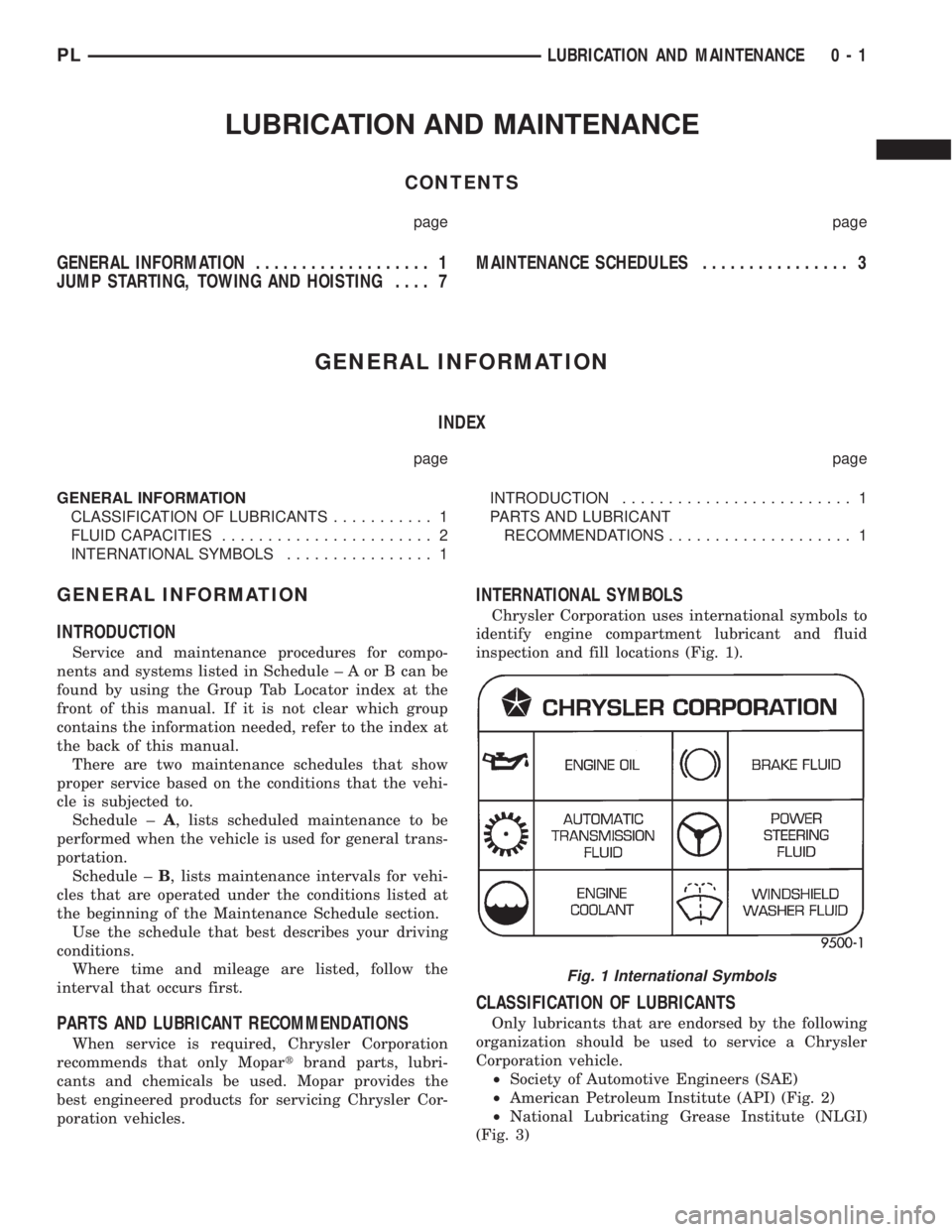
Chrysler Corporation uses international symbols to
identify engine compartment lubricant and fluid
inspection and fill locations (Fig. 1).
CLASSIFICATION OF LUBRICANTS
Only lubricants that are endorsed by the following
organization should be used to service a Chrysler
Corporation vehicle.
²Society of Automotive Engineers (SAE)
²American Petroleum Institute (API) (Fig. 2)
²National Lubricating Grease Institute (NLGI)
(Fig. 3)
Fig. 1 International Symbols
PLLUBRICATION AND MAINTENANCE 0 - 1
Page 4 of 1200
MAINTENANCE SCHEDULES
INDEX
page page
GENERAL INFORMATION
INTRODUCTION......................... 3
SCHEDULE ± A.......................... 3SCHEDULE ± B.......................... 4
UNSCHEDULED INSPECTION............... 3
GENERAL INFORMATION
INTRODUCTION
Service and maintenance procedures for compo-
nents and systems listed in Schedule ± A or B can be
found by using the Group Tab Locator index at the
front of this manual. If it is not clear which group
contains the information needed, refer to the index at
the back of this manual.
There are two maintenance schedules that show
proper service based on the conditions that the vehi-
cle is subjected to. Use the schedule that best
describes these conditions.
Schedule ±A, lists maintenance recommended for
vehicles used for general transportation.
Schedule ±B, lists maintenance recommended for
vehicles used under the following conditions:
²Frequent short trip driving less than 5 miles (8
km)
²Frequent driving in dusty conditions
²Frequent trailer towing
²Extensive idling
²More than 50% of your driving is at sustained
high speeds during hot weather, above 90ÉF (32ÉC)
Where time and mileage are listed, follow the
interval that occurs first.
EMISSION CONTROL SYSTEM MAINTENANCE
The scheduled emission maintenance listed inbold
typeon the Maintenance Schedules, must be done at
the mileage specified to assure the continued proper
functioning of the emission control system. These,
and all other maintenance services included in this
manual, should be done to provide the best vehicle
performance and reliability. More frequent mainte-
nance may be needed for vehicles in severe operating
conditions such as dusty areas and very short trip
driving.
UNSCHEDULED INSPECTION
At Each Stop For Fuel
²Check engine oil level, add as required.
²Check windshield washer solvent and add if
required.
Once A Month
²Check tire pressure and look for unusual wear
or damage.
²Inspect battery, clean, and tighten terminals as
required.
²Check fluid levels of coolant reservoir, power
steering and automatic transmission and add as
required.
²Check all lights and all other electrical items for
correct operation.
At Each Oil Change
²Inspect exhaust system.
²Inspect brake hoses.
²Inspect the CV joints and front suspension com-
ponents.
²Rotate the tires at each oil change interval
shown on Schedule ± A (7,500 miles) or every other
interval shown on schedule ± B (6,000 miles).
²Check coolant level, hoses and clamps.
²Check the manual transaxle fluid level.
²If the mileage is less than 7,500 miles (12 000
km) yearly, replace the engine oil filter at each oil
change.
SCHEDULE ± A
7,500 Miles (12 000 km) or at 6 months
²Change engine oil.
15,000 Miles (24 000 km) or at 12 months
²Change engine oil.
²Replace engine oil filter.
²Adjust drive belt tension.
22,500 Miles (36 000 km) or at 18 months
²Change engine oil.
²Inspect the front brake pads and rear brake lin-
ings.
30,000 Miles (48 000 km) or at 24 months
²Change engine oil.
²Replace engine oil filter.
²Lubricate front suspension ball joints.
²Adjust drive belt tension.
PLLUBRICATION AND MAINTENANCE 0 - 3
Page 8 of 1200
JUMP STARTING, TOWING AND HOISTING
INDEX
page page
SERVICE PROCEDURES
HOISTING RECOMMENDATIONS............ 9JUMP STARTING PROCEDURE.............. 7
TOWING RECOMMENDATIONS.............. 8
SERVICE PROCEDURES
JUMP STARTING PROCEDURE
WARNING: REVIEW ALL SAFETY PRECAUTIONS
AND WARNINGS IN GROUP 8A, BATTERY/START-
ING/CHARGING SYSTEMS DIAGNOSTICS. DO NOT
JUMP START A FROZEN BATTERY, PERSONAL
INJURY CAN RESULT. DO NOT JUMP START WHEN
MAINTENANCE FREE BATTERY INDICATOR DOT IS
YELLOW OR BRIGHT COLOR. DO NOT JUMP
START A VEHICLE WHEN THE BATTERY FLUID IS
BELOW THE TOP OF LEAD PLATES. DO NOT
ALLOW JUMPER CABLE CLAMPS TO TOUCH
EACH OTHER WHEN CONNECTED TO A BOOSTER
SOURCE. DO NOT USE OPEN FLAME NEAR BAT-
TERY. REMOVE METALLIC JEWELRY WORN ON
HANDS OR WRISTS TO AVOID INJURY BY ACCI-
DENTAL ARCING OF BATTERY CURRENT. WHEN
USING A HIGH OUTPUT BOOSTING DEVICE, DO
NOT ALLOW BATTERY VOLTAGE TO EXCEED 16
VOLTS. REFER TO INSTRUCTIONS PROVIDED
WITH DEVICE BEING USED.
CAUTION: When using another vehicle as a
booster, do not allow vehicles to touch. Electrical
systems can be damaged on either vehicle.
TO JUMP START A DISABLED VEHICLE:
(1) Raise hood on disabled vehicle and visually
inspect engine compartment for:
²Battery cable clamp condition, clean if necessary.
²Frozen battery.
²Yellow or bright color test indicator, if equipped.
²Low battery fluid level.
²Generator drive belt condition and tension.
²Fuel fumes or leakage, correct if necessary.
CAUTION: If the cause of starting problem on dis-
abled vehicle is severe, damage to booster vehicle
charging system can result.
(2) When using another vehicle as a booster
source, park the booster vehicle within cable reach.
Turn off all accessories, set the parking brake, placethe automatic transmission in PARK or the manual
transmission in NEUTRAL and turn the ignition
OFF.
(3) On disabled vehicle, place gear selector in park
or neutral and set park brake. Turn off all accesso-
ries.
(4) Connect jumper cables to booster battery. RED
clamp to positive terminal (+). BLACK clamp to neg-
ative terminal (-). DO NOT allow clamps at opposite
end of cables to touch, electrical arc will result.
Review all warnings in this procedure.
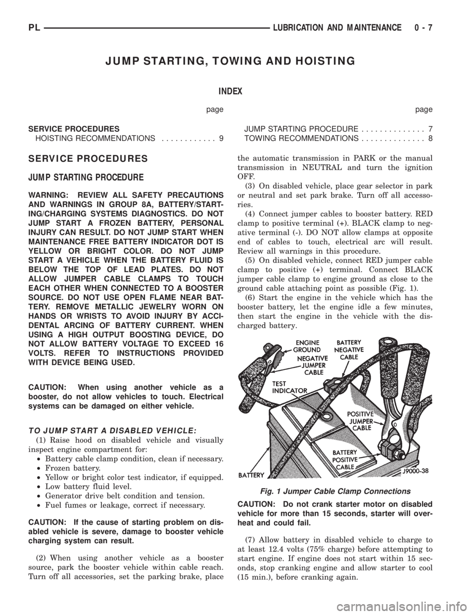
(5) On disabled vehicle, connect RED jumper cable
clamp to positive (+) terminal. Connect BLACK
jumper cable clamp to engine ground as close to the
ground cable attaching point as possible (Fig. 1).
(6) Start the engine in the vehicle which has the
booster battery, let the engine idle a few minutes,
then start the engine in the vehicle with the dis-
charged battery.
CAUTION: Do not crank starter motor on disabled
vehicle for more than 15 seconds, starter will over-
heat and could fail.
(7) Allow battery in disabled vehicle to charge to
at least 12.4 volts (75% charge) before attempting to
start engine. If engine does not start within 15 sec-
onds, stop cranking engine and allow starter to cool
(15 min.), before cranking again.
Fig. 1 Jumper Cable Clamp Connections
PLLUBRICATION AND MAINTENANCE 0 - 7
Page 9 of 1200
DISCONNECT CABLE CLAMPS AS FOLLOWS:
²Disconnect BLACK cable clamp from engine
ground on disabled vehicle.
²When using a Booster vehicle, disconnect
BLACK cable clamp from battery negative terminal.
Disconnect RED cable clamp from battery positive
terminal.
²Disconnect RED cable clamp from battery posi-
tive terminal on disabled vehicle.
TOWING RECOMMENDATIONS
WARNING: DO NOT ALLOW TOWING ATTACH-
MENT DEVICES TO CONTACT THE FUEL TANK OR
LINES, FUEL LEAK CAN RESULT. DO NOT LIFT OR
TOW VEHICLE BY FRONT OR REAR BUMPER, OR
BUMPER ENERGY ABSORBER UNITS. DO NOT
VENTURE UNDER A LIFTED VEHICLE IF NOT SUP-
PORTED PROPERLY ON SAFETY STANDS. DO NOT
ALLOW PASSENGERS TO RIDE IN A TOWED VEHI-
CLE. USE A SAFETY CHAIN THAT IS INDEPENDENT
FROM THE TOWING ATTACHMENT DEVICE.
CAUTION: Do not damage brake lines, exhaust
system, shock absorbers, sway bars, or any other
under vehicle components when attaching towing
device to vehicle. Do not attach towing device to
front or rear suspension components. Do not
secure vehicle to towing device by the use of front
or rear suspension or steering components.
Remove or secure loose or protruding objects from
a damaged vehicle before towing. Refer to state and
local rules and regulations before towing a vehicle.
Do not allow weight of towed vehicle to bear on
lower fascia, air dams, or spoilers.
RECOMMENDED TOWING EQUIPMENT
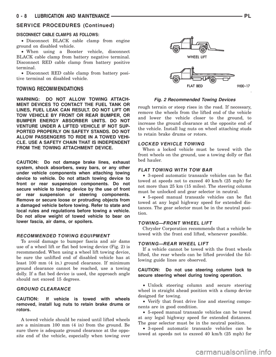
To avoid damage to bumper fascia and air dams
use of a wheel lift or flat bed towing device (Fig. 2) is
recommended. When using a wheel lift towing device,
be sure the unlifted end of disabled vehicle has at
least 100 mm (4 in.) ground clearance. If minimum
ground clearance cannot be reached, use a towing
dolly. If a flat bed device is used, the approach angle
should not exceed 15 degrees.
GROUND CLEARANCE
CAUTION: If vehicle is towed with wheels
removed, install lug nuts to retain brake drums or
rotors.
A towed vehicle should be raised until lifted wheels
are a minimum 100 mm (4 in) from the ground. Be
sure there is adequate ground clearance at the oppo-
site end of the vehicle, especially when towing overrough terrain or steep rises in the road. If necessary,
remove the wheels from the lifted end of the vehicle
and lower the vehicle closer to the ground, to
increase the ground clearance at the opposite end of
the vehicle. Install lug nuts on wheel attaching studs
to retain brake drums or rotors.
LOCKED VEHICLE TOWING
When a locked vehicle must be towed with the
front wheels on the ground, use a towing dolly or flat
bed hauler.
FLAT TOWING WITH TOW BAR
²3-speed automatic transaxle vehicles can be flat
towed at speeds not to exceed 40 km/h (25 mph) for
not more than 25 km (15 miles). The steering column
must be unlocked and gear selector in neutral.
²5-speed manual transaxle vehicles can be flat
towed at any legal highway speed for extended dis-
tances. The gear selector must be in the neutral posi-
tion.
TOWINGÐFRONT WHEEL LIFT
Chrysler Corporation recommends that a vehicle be
towed with the front end lifted, whenever possible.
TOWINGÐREAR WHEEL LIFT
If a vehicle cannot be towed with the front wheels
lifted, the rear wheels can be lifted provided the fol-
lowing guide lines are observed.
CAUTION: Do not use steering column lock to
secure steering wheel during towing operation.
²Unlock steering column and secure steering
wheel in straight ahead position with a clamp device
designed for towing.
²Verify that front drive line and steering compo-
nents are in good condition.
²5-speed manual transaxle vehicles can be towed
at any legal highway speed for extended distances.
The gear selector must be in the neutral position.
²3-speed automatic transaxle vehicles can be
towed at speeds not to exceed 40 km/h (25 mph) for
Fig. 2 Recommended Towing Devices
0 - 8 LUBRICATION AND MAINTENANCEPL
SERVICE PROCEDURES (Continued)
Page 18 of 1200
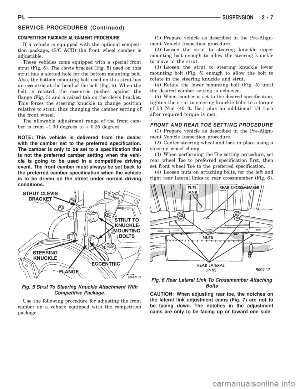
COMPETITION PACKAGE ALIGNMENT PROCEDURE
If a vehicle is equipped with the optional competi-
tion package, (S/C ACR) the front wheel camber is
adjustable.
These vehicles come equipped with a special front
strut (Fig. 5). The clevis bracket (Fig. 5) used on this
strut has a slotted hole for the bottom mounting bolt.
Also, the bottom mounting bolt used on this strut has
an eccentric at the head of the bolt (Fig. 5). When the
bolt is rotated, the eccentric pushes against the
flange (Fig. 5) and a raised tab on the clevis bracket.
This forces the steering knuckle to change position
relative to strut, thus changing the camber setting of
the front wheel.
The allowable adjustment range of the front cam-
ber is from ±1.00 degrees to + 0.25 degrees.
NOTE: This vehicle is delivered from the dealer
with the camber set to the preferred specification.
The camber is only to be set to a specification that
is not the preferred camber setting when the vehi-
cle is going to be used in a competitive driving
event. The front camber must always be set back to
the preferred camber specification when the vehicle
is to be driven on the street under normal driving
conditions.
Use the following procedure for adjusting the front
camber on a vehicle equipped with the competition
package.(1) Prepare vehicle as described in the Pre-Align-
ment Vehicle Inspection procedure.
(2) Loosen the strut to steering knuckle upper
mounting bolt enough to allow the steering knuckle
to move in the strut.
(3) Loosen the strut to steering knuckle lower
mounting bolt (Fig. 5) enough to allow the bolt to
rotate in the steering knuckle and strut.
(4) Rotate the lower mounting bolt (Fig. 5) until
the desired camber setting is achieved.
(5) When camber is set to the desired specification,
tighten the strut to steering knuckle bolts to a torque
of 53 N´m (40 ft. lbs.) plus an additional 1/4 turn
after required torque is met.
FRONT AND REAR TOE SETTING PROCEDURE
(1) Prepare vehicle as described in the Pre-Align-
ment Vehicle Inspection procedure.
(2) Center steering wheel and lock in place using a
steering wheel clamp.
(3) When performing the Toe setting procedure, set
rear wheel Toe to preferred specification first, then
set front wheel Toe to the preferred specification.
(4) Loosen nuts on attaching bolts, for the left and
right rear lateral links to rear crossmember (Fig. 6).
CAUTION: When adjusting rear toe, the notches on
the lateral link adjustment cams (Fig. 7) are not to
be facing down. The notches in the adjustment
cams are only to be facing up or toward one side.
Fig. 5 Strut To Steering Knuckle Attachment With
Competitive Package.
Fig. 6 Rear Lateral Link To Crossmember Attaching
Bolts
PLSUSPENSION 2 - 7
SERVICE PROCEDURES (Continued)
Page 21 of 1200
FRONT SUSPENSION
INDEX
page page
GENERAL INFORMATION
GENERAL INFORMATION................. 10
DESCRIPTION AND OPERATION
BALL JOINT............................ 14
COIL SPRING........................... 14
COMPETITION PACKAGE SUSPENSION...... 13
FRONT SUSPENSION.................... 11
FRONT WHEEL HUB BEARING............. 14
LOWER CONTROL ARM.................. 13
McPHERSON STRUT..................... 13
STABILIZER BAR........................ 14
STEERING KNUCKLE.................... 13
WHEEL MOUNTING STUDS................ 14
DIAGNOSIS AND TESTING
BALL JOINT ASSEMBLY................... 16
HUB/BEARING.......................... 16
LOWER CONTROL ARM.................. 15
MCPHERSON STRUT ASSEMBLY........... 15
STABILIZER BAR........................ 16
STEERING KNUCKLE.................... 15
REMOVAL AND INSTALLATION
FRONT WHEEL MOUNTING STUDS......... 28LOWER CONTROL ARM.................. 21
MCPHERSON STRUT.................... 16
STABILIZER BAR........................ 23
STEERING KNUCKLE.................... 17
WHEEL BEARING....................... 25
DISASSEMBLY AND ASSEMBLY
BALL JOINT............................ 32
LOWER CONTROL ARM FRONT
ISOLATOR BUSHING................... 33
LOWER CONTROL ARM REAR ISOLATOR
BUSHING............................ 34
McPHERSON STRUT..................... 30
ADJUSTMENTS
STRUT ADJUSTMENT COMPETITION
PACKAGE SUSPENSION................ 36
SPECIFICATIONS
FRONT SUSPENSION FASTENER
TORQUES............................ 36
SPECIAL TOOLS
FRONT SUSPENSION.................... 37
GENERAL INFORMATION
GENERAL INFORMATION
CAUTION: ONLY FRAME CONTACT HOISTING
EQUIPMENT CAN BE USED ON THIS VEHICLE. All
vehicles have a fully independent rear suspension.
The vehicles can not be hoisted using equipment
designed to lift a vehicle by the rear axle. If this
type of hoisting equipment is used, damage to rear
suspension components will occur.
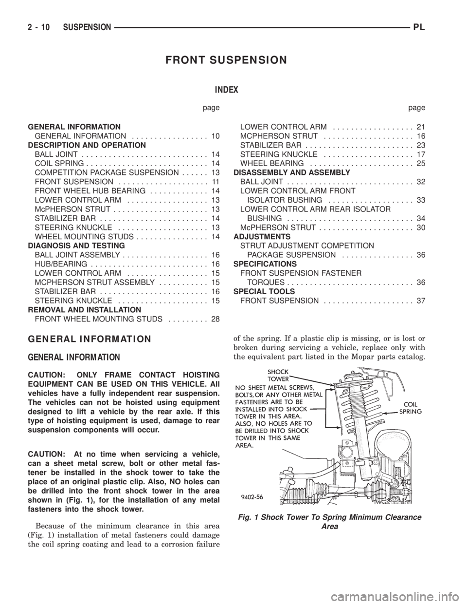
CAUTION: At no time when servicing a vehicle,
can a sheet metal screw, bolt or other metal fas-
tener be installed in the shock tower to take the
place of an original plastic clip. Also, NO holes can
be drilled into the front shock tower in the area
shown in (Fig. 1), for the installation of any metal
fasteners into the shock tower.
Because of the minimum clearance in this area
(Fig. 1) installation of metal fasteners could damage
the coil spring coating and lead to a corrosion failureof the spring. If a plastic clip is missing, or is lost or
broken during servicing a vehicle, replace only with
the equivalent part listed in the Mopar parts catalog.
Fig. 1 Shock Tower To Spring Minimum Clearance
Area
2 - 10 SUSPENSIONPL
Page 22 of 1200
DESCRIPTION AND OPERATION
FRONT SUSPENSION
This vehicle has a gas pressurized MacPherson
strut front suspension design (Fig. 2).
A MacPherson strut assembly is used in place of
the front suspension upper control arm and upper
ball joint. The bottom of the MacPherson strut,
mounts directly to the steering knuckle using 2
attaching bolts and nuts going through the clevis
bracket and steering knuckle (Fig. 2). The top of the
strut is mounted directly to the strut tower of the
vehicle by the strut mount assembly's 3 studs and
attaching nuts (Fig. 2). During steering maneuvers,
the strut assembly (through a pivot bearing in the
upper strut mount assembly) and steering knuckle(through the lower ball joint) turn as an assembly
(Fig. 2).
The MacPherson strut assembly includes the fol-
lowing components: A rubber isolated top mount, an
upper spring seat/bearing assembly, jounce bumper,
dust shield, coil spring with plastic noise insulator
and the strut dampener.
A cast lower control arm assembly (Fig. 2) is
attached to the front suspension crossmember using
2 rubber isolator bushings and to the steering
knuckle by means of a ball joint.
A sealed for life front hub and bearing assembly is
attached to the front steering knuckle. The outer C/V
joint assembly is splined to the front hub and bear-
ing assembly and is retained by a prevailing torque
nut.
PLSUSPENSION 2 - 11
Page 24 of 1200
COMPETITION PACKAGE SUSPENSION
On vehicles that are equipped with the optional
competition package, special front struts are used.
The front struts used on a vehicle equipped with
the competition package are adjustable. The adjust-
able front struts use a unique strut shaft which has
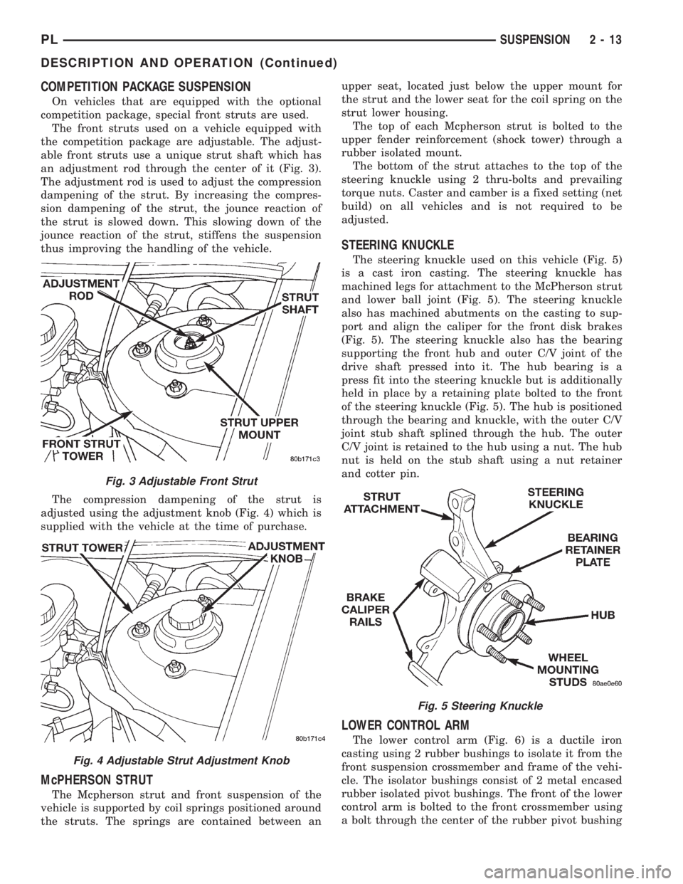
an adjustment rod through the center of it (Fig. 3).
The adjustment rod is used to adjust the compression
dampening of the strut. By increasing the compres-
sion dampening of the strut, the jounce reaction of
the strut is slowed down. This slowing down of the
jounce reaction of the strut, stiffens the suspension
thus improving the handling of the vehicle.
The compression dampening of the strut is
adjusted using the adjustment knob (Fig. 4) which is
supplied with the vehicle at the time of purchase.
McPHERSON STRUT
The Mcpherson strut and front suspension of the
vehicle is supported by coil springs positioned around
the struts. The springs are contained between anupper seat, located just below the upper mount for
the strut and the lower seat for the coil spring on the
strut lower housing.
The top of each Mcpherson strut is bolted to the
upper fender reinforcement (shock tower) through a
rubber isolated mount.
The bottom of the strut attaches to the top of the
steering knuckle using 2 thru-bolts and prevailing
torque nuts. Caster and camber is a fixed setting (net
build) on all vehicles and is not required to be
adjusted.
STEERING KNUCKLE
The steering knuckle used on this vehicle (Fig. 5)
is a cast iron casting. The steering knuckle has
machined legs for attachment to the McPherson strut
and lower ball joint (Fig. 5). The steering knuckle
also has machined abutments on the casting to sup-
port and align the caliper for the front disk brakes
(Fig. 5). The steering knuckle also has the bearing
supporting the front hub and outer C/V joint of the
drive shaft pressed into it. The hub bearing is a
press fit into the steering knuckle but is additionally
held in place by a retaining plate bolted to the front
of the steering knuckle (Fig. 5). The hub is positioned
through the bearing and knuckle, with the outer C/V
joint stub shaft splined through the hub. The outer
C/V joint is retained to the hub using a nut. The hub
nut is held on the stub shaft using a nut retainer
and cotter pin.
LOWER CONTROL ARM
The lower control arm (Fig. 6) is a ductile iron
casting using 2 rubber bushings to isolate it from the
front suspension crossmember and frame of the vehi-
cle. The isolator bushings consist of 2 metal encased
rubber isolated pivot bushings. The front of the lower
control arm is bolted to the front crossmember using
a bolt through the center of the rubber pivot bushing
Fig. 3 Adjustable Front Strut
Fig. 4 Adjustable Strut Adjustment Knob
Fig. 5 Steering Knuckle
PLSUSPENSION 2 - 13
DESCRIPTION AND OPERATION (Continued)
Page 25 of 1200
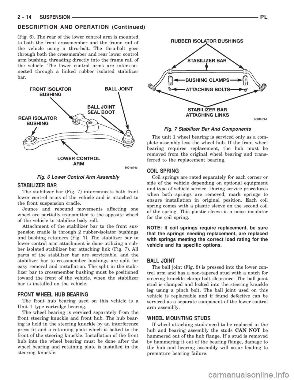
(Fig. 6). The rear of the lower control arm is mounted
to both the front crossmember and the frame rail of
the vehicle using a thru-bolt. The thru-bolt goes
through both the crossmember and rear lower control
arm bushing, threading directly into the frame rail of
the vehicle. The lower control arms are inter-con-
nected through a linked rubber isolated stabilizer
bar.
STABILIZER BAR
The stabilizer bar (Fig. 7) interconnects both front
lower control arms of the vehicle and is attached to
the front suspension cradle.
Jounce and rebound movements affecting one
wheel are partially transmitted to the opposite wheel
of the vehicle to stabilize body roll.
Attachment of the stabilizer bar to the front sus-
pension cradle is through 2 rubber-isolator bushings
and bushing retainers (Fig. 7). The stabilizer bar to
lower control arm attachment is done utilizing a rub-
ber isolated stabilizer bar attaching link (Fig. 7). All
parts of the stabilizer bar are serviceable, and the
stabilizer bar to crossmember bushings are split for
easy removal and installation. The split in the stabi-
lizer bar to crossmember bushing must be positioned
toward the front of the vehicle, when the stabilizer
bar is installed on the vehicle.
FRONT WHEEL HUB BEARING
The front hub bearing used on this vehicle is a
Unit 1 type cartridge bearing.
The wheel bearing is serviced separately from the
front steering knuckle and front hub. The hub bear-
ing is held in the steering knuckle by an interference
press fit and a retaining plate which is bolted to the
front of the steering knuckle. Installation of the front
hub into the wheel bearing must be done after the
wheel bearing and retaining plate is installed in the
steering knuckle.The unit 1 wheel bearing is serviced only as a com-
plete assembly less the wheel hub. If the front wheel
bearing requires replacement, the hub must be
removed from the original wheel bearing and trans-
ferred to the replacement bearing.
COIL SPRING
Coil springs are rated separately for each corner or
side of the vehicle depending on optional equipment
and type of vehicle service. During service procedures
when both springs are removed, mark springs to
ensure installation in original position. Each coil
spring comes with a plastic sleeve on the second coil
of the spring. This plastic sleeve is a noise insulator
for the coil spring.
NOTE: If coil springs require replacement, be sure
that the springs needing replacement, are replaced
with springs meeting the correct load rating for the
vehicle and its specific options.
BALL JOINT
The ball joint (Fig. 8) is pressed into the lower con-
trol arm and has a non-tapered stud with a notch for
steering knuckle clamp bolt clearance. The ball joint
stud is clamped and locked into the steering knuckle
leg using a pinch bolt. The ball joint used on this
vehicle is replaceable and if found defective can be
serviced as a separate component of the lower control
arm assembly.
WHEEL MOUNTING STUDS
If wheel attaching studs need to be replaced in the
hub and bearing assembly the studsCAN NOTbe
hammered out of the hub flange. If a stud is removed
by hammering it out of the bearing flange, damage to
the hub and bearing assembly will occur leading to
premature bearing failure.
Fig. 6 Lower Control Arm Assembly
Fig. 7 Stabilizer Bar And Components
2 - 14 SUSPENSIONPL
DESCRIPTION AND OPERATION (Continued)
Page 27 of 1200
nent removal and installation sections in this group
of the service manual.
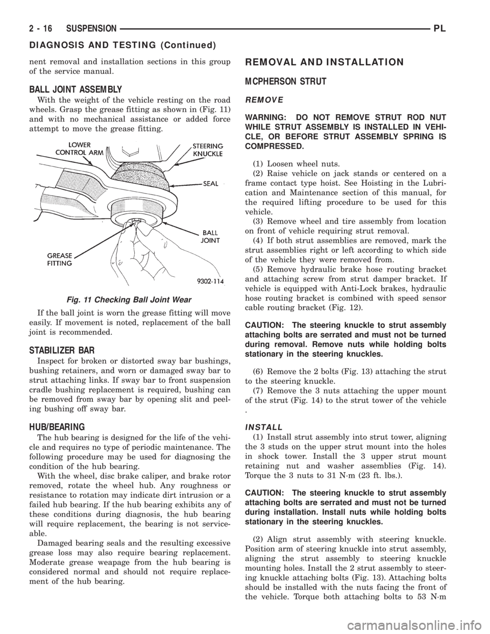
BALL JOINT ASSEMBLY
With the weight of the vehicle resting on the road
wheels. Grasp the grease fitting as shown in (Fig. 11)
and with no mechanical assistance or added force
attempt to move the grease fitting.
If the ball joint is worn the grease fitting will move
easily. If movement is noted, replacement of the ball
joint is recommended.
STABILIZER BAR
Inspect for broken or distorted sway bar bushings,
bushing retainers, and worn or damaged sway bar to
strut attaching links. If sway bar to front suspension
cradle bushing replacement is required, bushing can
be removed from sway bar by opening slit and peel-
ing bushing off sway bar.
HUB/BEARING
The hub bearing is designed for the life of the vehi-
cle and requires no type of periodic maintenance. The
following procedure may be used for diagnosing the
condition of the hub bearing.
With the wheel, disc brake caliper, and brake rotor
removed, rotate the wheel hub. Any roughness or
resistance to rotation may indicate dirt intrusion or a
failed hub bearing. If the hub bearing exhibits any of
these conditions during diagnosis, the hub bearing
will require replacement, the bearing is not service-
able.
Damaged bearing seals and the resulting excessive
grease loss may also require bearing replacement.
Moderate grease weapage from the hub bearing is
considered normal and should not require replace-
ment of the hub bearing.
REMOVAL AND INSTALLATION
MCPHERSON STRUT
REMOVE
WARNING: DO NOT REMOVE STRUT ROD NUT
WHILE STRUT ASSEMBLY IS INSTALLED IN VEHI-
CLE, OR BEFORE STRUT ASSEMBLY SPRING IS
COMPRESSED.
(1) Loosen wheel nuts.
(2) Raise vehicle on jack stands or centered on a
frame contact type hoist. See Hoisting in the Lubri-
cation and Maintenance section of this manual, for
the required lifting procedure to be used for this
vehicle.
(3) Remove wheel and tire assembly from location
on front of vehicle requiring strut removal.
(4) If both strut assemblies are removed, mark the
strut assemblies right or left according to which side
of the vehicle they were removed from.
(5) Remove hydraulic brake hose routing bracket
and attaching screw from strut damper bracket. If
vehicle is equipped with Anti-Lock brakes, hydraulic
hose routing bracket is combined with speed sensor
cable routing bracket (Fig. 12).
CAUTION: The steering knuckle to strut assembly
attaching bolts are serrated and must not be turned
during removal. Remove nuts while holding bolts
stationary in the steering knuckles.
(6) Remove the 2 bolts (Fig. 13) attaching the strut
to the steering knuckle.
(7) Remove the 3 nuts attaching the upper mount
of the strut (Fig. 14) to the strut tower of the vehicle
.
INSTALL
(1) Install strut assembly into strut tower, aligning
the 3 studs on the upper strut mount into the holes
in shock tower. Install the 3 upper strut mount
retaining nut and washer assemblies (Fig. 14).
Torque the 3 nuts to 31 N´m (23 ft. lbs.).
CAUTION: The steering knuckle to strut assembly
attaching bolts are serrated and must not be turned
during installation. Install nuts while holding bolts
stationary in the steering knuckles.
(2) Align strut assembly with steering knuckle.
Position arm of steering knuckle into strut assembly,
aligning the strut assembly to steering knuckle
mounting holes. Install the 2 strut assembly to steer-
ing knuckle attaching bolts (Fig. 13). Attaching bolts
should be installed with the nuts facing the front of
the vehicle. Torque both attaching bolts to 53 N´m
Fig. 11 Checking Ball Joint Wear
2 - 16 SUSPENSIONPL
DIAGNOSIS AND TESTING (Continued)