set clock DODGE NEON 1999 Service Repair Manual
[x] Cancel search | Manufacturer: DODGE, Model Year: 1999, Model line: NEON, Model: DODGE NEON 1999Pages: 1200, PDF Size: 35.29 MB
Page 64 of 1200
mount and all tension is relieved from the spring
compressors.
(11) Install the strut assembly back into the vehi-
cle. Refer to Strut Assembly Removal in Servicing
Rear Struts in this section of the service manual.
(12) Check and reset rear wheel TOE to specifica-
tions if required.
STABILIZER BAR BUSHINGS
(1) If stabilizer bar to frame rail bushings require
replacement at time of inspection, install new bush-
ings before installing stabilizer bar. Bushings are
replaced by opening slit on bushings and peeling
them off stabilizer bar. Install new bushings on sta-
bilizer bar, by spreading bushing at slit and forcing
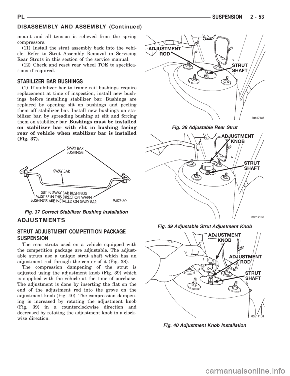
them on stabilizer bar.Bushings must be installed
on stabilizer bar with slit in bushing facing
rear of vehicle when stabilizer bar is installed
(Fig. 37).
ADJUSTMENTS
STRUT ADJUSTMENT COMPETITION PACKAGE
SUSPENSION
The rear struts used on a vehicle equipped with
the competition package are adjustable. The adjust-
able struts use a unique strut shaft which has an
adjustment rod through the center of it (Fig. 38).
The compression dampening of the strut is
adjusted using the adjustment knob (Fig. 39) which
is supplied with the vehicle at the time of purchase.
The adjustment is done by inserting the flat on the
end of the adjustment rod into the grove on the
adjustment knob (Fig. 40). The compression dampen-
ing is increased by rotating the adjustment knob
(Fig. 39) in a counterclockwise direction and
decreased by rotating the adjustment knob in a clock-
wise direction.
Fig. 37 Correct Stabilizer Bushing Installation
Fig. 38 Adjustable Rear Strut
Fig. 39 Adjustable Strut Adjustment Knob
Fig. 40 Adjustment Knob Installation
PLSUSPENSION 2 - 53
DISASSEMBLY AND ASSEMBLY (Continued)
Page 271 of 1200
When the ignition switch is in the OFF position, or
when the radio frequency is being displayed, time
keeping is accurately maintained.
The procedure for setting the clock varies slightly
with each radio. The correct procedure is described in
the individual radio operating instructions. Refer to
the Owner's Manual supplied with the vehicle.
INSTRUMENT CLUSTER
There are two conventional instrument cluster
assemblies available. The clusters electronically drive
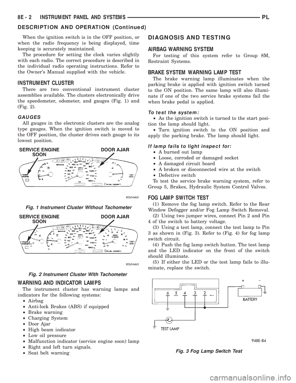
the speedometer, odometer, and gauges (Fig. 1) and
(Fig. 2).
GAUGES
All gauges in the electronic clusters are the analog
type gauges. When the ignition switch is moved to
the OFF position, the cluster drives each gauge to its
lowest position.
WARNING AND INDICATOR LAMPS
The instrument cluster has warning lamps and
indicators for the following systems:
²Airbag
²Anti-lock Brakes (ABS) if equipped
²Brake warning
²Charging System
²Door Ajar
²High beam indicator
²Low oil pressure
²Malfunction indicator (service engine soon) lamp
²Right and left turn signals.
²Seat belt warning
DIAGNOSIS AND TESTING
AIRBAG WARNING SYSTEM
For testing of this system refer to Group 8M,
Restraint Systems.
BRAKE SYSTEM WARNING LAMP TEST
The brake warning lamp illuminates when the
parking brake is applied with ignition switch turned
to the ON position. The same lamp will also illumi-
nate if one of the two service brake systems fail the
when brake pedal is applied.
To test the system:
²As the ignition switch is turned to the start posi-
tion the lamp should light.
²Turn ignition switch to the ON position and
apply the parking brake. The lamp should light.
If lamp fails to light inspect for:
²A burned out lamp
²Loose, corroded or damaged socket
²A damaged circuit board
²A broken or disconnected wire at the switch
²Defective switch
To test the service brake warning system, refer to
Group 5, Brakes, Hydraulic System Control Valves.
FOG LAMP SWITCH TEST
(1) Remove the fog lamp switch. Refer to the Rear
Window Defogger and/or Fog Lamp Switch Removal.
(2) Using two jumper wires, connect Pin 2 and Pin
4 of the switch to battery voltage.
(3) Using a test lamp, connect the test lamp to Pin
3 as shown in (Fig. 3). Refer to (Fig. 4) for fog lamp
switch circuit.
(4) Push the fog lamp switch button. The test lamp
and the LED indicator on the front of the switch
should illuminate.
(5) If either the LED or the test lamp fails to illu-
minate, replace the switch.Fig. 1 Instrument Cluster Without Tachometer
Fig. 2 Instrument Cluster With Tachometer
Fig. 3 Fog Lamp Switch Test
8E - 2 INSTRUMENT PANEL AND SYSTEMSPL
DESCRIPTION AND OPERATION (Continued)
Page 288 of 1200
AUDIO SYSTEM
CONTENTS
page page
GENERAL INFORMATION
INTRODUCTION......................... 1
DESCRIPTION AND OPERATION
INTERFERENCE ELIMINATION.............. 1
DIAGNOSIS AND TESTING
ANTENNA.............................. 3
AUDIO DIAGNOSTIC TEST PROCEDURES..... 1BENCH TEST FOR ANTENNA MALFUNCTION . . 3
REMOVAL AND INSTALLATION
ANTENNA.............................. 3
FRONT DOOR SPEAKER................... 4
INSTRUMENT PANEL SPEAKER............. 4
RADIO................................. 4
REAR SHELF SPEAKER(S)................. 5
GENERAL INFORMATION
INTRODUCTION
Operating instructions for the factory installed
audio systems can be found in the Owner's Manual
provided with the vehicle.
The vehicles are equipped with an Interior (Igni-
tion Off Draw) fuse in the Power Distribution Center
located in the engine compartment. After the Interior
(IOD) fuse or battery has been disconnected the clock
will require resetting.
DESCRIPTION AND OPERATION
INTERFERENCE ELIMINATION
The radio utilizes a ground wire plugged on to a
blade terminal and is bolted to the radio chassis.
Both connector and terminal should be securely
attached. The engine has three separate ground
straps to suppress ignition noise which may interfere
with radio reception.
²Left engine mount clip on strap
²Engine to shock tower reinforcement
²Rear strut to body, clip-on strap
Inductive type spark plug cables in the high ten-
sion circuit of the ignition system complete the inter-
ference suppression. Faulty or deteriorated spark
plug wires should be replaced.
In addition, there is a capacitor mounted on the
cylinder head which also helps suppress ignition
noise.
DIAGNOSIS AND TESTING
AUDIO DIAGNOSTIC TEST PROCEDURES
CAUTION: The CD player will only operate between
approximate temperatures of -23ÉC and +65ÉC (-10ÉF
and +145ÉF).
Whenever a radio malfunction occurs;
(1) First check FUSES:
(a) Power Distribution Center (PDC), Interior
lamp fuse, M1 - Radio Memory Feed
(b) Fuse Block:
(I) Fuse 12, Illumination in the fuse block
(II) Fuse 16, Ignition feed in the fuse block
NOTE: The vehicles are shipped with the INTERIOR
LAMP fuse disconnected.
(2) Verify, the radio wire harness are properly con-
nected before starting normal diagnosis and repair
procedures. Refer to Audio Diagnosis table and/or
Group 8W, Wiring Diagrams, Radio Section.
PLAUDIO SYSTEM 8F - 1
Page 305 of 1200
(c) If continuity is OK between cavity 62 and
cavity 1, repair open circuit between cavity 2 of the
stop lamp switch connector and ground.
(6) Using an ohmmeter, check continuity from cav-
ity 76 on PCM connector to ground with the trans-
mission in park or neutral. If no continuity, test TRS/
Park-Neutral switch and switch wiring
(7) Turn speed control and ignition switch OFF.
(8) Unplug the BLACK 40-way connector from the
Powertrain Control Module (PCM)
(9) Using an ohmmeter, check continuity from cav-
ity 3 of servo connector to cavity 5 on the PCM con-
nector.
(a) If continuity is OK, replace PCM. Check cir-
cuit for short to ground before replacing PCM.
(b) If no continuity, remove stop lamp switch
and conduct Stop Lamp Switch Test. If test fails,
adjust or replace as necessary.
(c) If switch passes, measure continuity from
cavity 4 of stop lamp switch connector to cavity 3
of servo connector. Repair open circuit if necessary.
(d) If continuity is OK, measure continuity from
cavity 3 of stop lamp switch to cavity 5 of PCM
connector. Repair open circuit as necessary.
(e) Install PCM connectors onto PCM and speed
control servo connector to servo.
VACUUM SUPPLY TEST
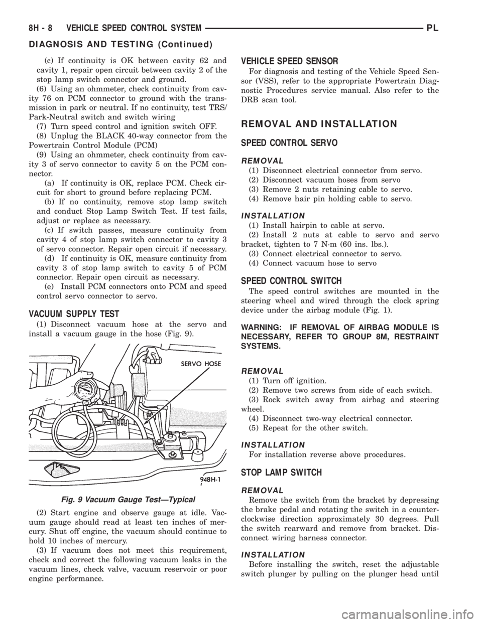
(1) Disconnect vacuum hose at the servo and
install a vacuum gauge in the hose (Fig. 9).
(2) Start engine and observe gauge at idle. Vac-
uum gauge should read at least ten inches of mer-
cury. Shut off engine, the vacuum should continue to
hold 10 inches of mercury.
(3) If vacuum does not meet this requirement,
check and correct the following vacuum leaks in the
vacuum lines, check valve, vacuum reservoir or poor
engine performance.
VEHICLE SPEED SENSOR
For diagnosis and testing of the Vehicle Speed Sen-
sor (VSS), refer to the appropriate Powertrain Diag-
nostic Procedures service manual. Also refer to the
DRB scan tool.
REMOVAL AND INSTALLATION
SPEED CONTROL SERVO
REMOVAL
(1) Disconnect electrical connector from servo.
(2) Disconnect vacuum hoses from servo
(3) Remove 2 nuts retaining cable to servo.
(4) Remove hair pin holding cable to servo.
INSTALLATION
(1) Install hairpin to cable at servo.
(2) Install 2 nuts at cable to servo and servo
bracket, tighten to 7 N´m (60 ins. lbs.).
(3) Connect electrical connector to servo.
(4) Connect vacuum hose to servo
SPEED CONTROL SWITCH
The speed control switches are mounted in the
steering wheel and wired through the clock spring
device under the airbag module (Fig. 1).
WARNING: IF REMOVAL OF AIRBAG MODULE IS
NECESSARY, REFER TO GROUP 8M, RESTRAINT
SYSTEMS.
REMOVAL
(1) Turn off ignition.
(2) Remove two screws from side of each switch.
(3) Rock switch away from airbag and steering
wheel.
(4) Disconnect two-way electrical connector.
(5) Repeat for the other switch.
INSTALLATION
For installation reverse above procedures.
STOP LAMP SWITCH
REMOVAL
Remove the switch from the bracket by depressing
the brake pedal and rotating the switch in a counter-
clockwise direction approximately 30 degrees. Pull
the switch rearward and remove from bracket. Dis-
connect wiring harness connector.
INSTALLATION
Before installing the switch, reset the adjustable
switch plunger by pulling on the plunger head until
Fig. 9 Vacuum Gauge TestÐTypical
8H - 8 VEHICLE SPEED CONTROL SYSTEMPL
DIAGNOSIS AND TESTING (Continued)
Page 354 of 1200
DIAGNOSIS AND TESTING
AIRBAG SYSTEM TEST
(1) Disconnect and isolate the negative battery
cable.
(2) Connect scan tool (DRB) to Data Link connec-
tor, located at right side of the steering column and
at the lower edge of the lower instrument panel.
(3) Turn the ignition key to ON position. Exit vehi-
cle with scan tool. Use the latest version of the
proper cartridge.
(4) After checking that no one is inside the vehicle,
connect the battery negative terminal.
(5) Using the scan tool, read and record active
diagnostic code data.
(6) Read and record any stored diagnostic codes.
(7) Refer to the Passive Restraint Diagnostic Test
Manual if any diagnostic codes are found in Step 5 or
Step 6.
(8) Erase stored diagnostic codes if there are no
active diagnostic codes. If problems remain, diagnos-
tic codes will not erase. Refer to the Passive
Restraint Diagnostic Test Manual to diagnose the
problem.If the airbag warning lamp either fails
to light with the ignition switch on, or the light
goes on and stays on, there is a system malfunc-
tion. Refer to the Passive Restraint Diagnostic
Test Manual to diagnose the problem.
SERVICE PROCEDURES
CLEANUP PROCEDURE
Roll or fold the passenger airbag towards the
instrument panel surface and close the door over the
folded bag. Then tape the door shut.
Use a vacuum cleaner to remove any residual pow-
der from the vehicle interior. Work from the outside
in to avoid kneeling or sitting in a contaminated
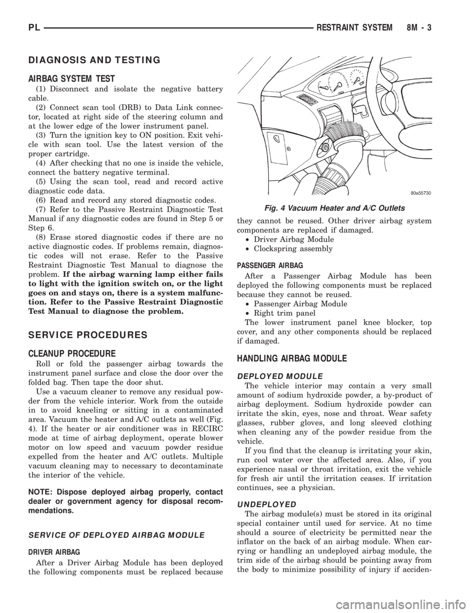
area. Vacuum the heater and A/C outlets as well (Fig.
4). If the heater or air conditioner was in RECIRC
mode at time of airbag deployment, operate blower
motor on low speed and vacuum powder residue
expelled from the heater and A/C outlets. Multiple
vacuum cleaning may to necessary to decontaminate
the interior of the vehicle.
NOTE: Dispose deployed airbag properly, contact
dealer or government agency for disposal recom-
mendations.
SERVICE OF DEPLOYED AIRBAG MODULE
DRIVER AIRBAG
After a Driver Airbag Module has been deployed
the following components must be replaced becausethey cannot be reused. Other driver airbag system
components are replaced if damaged.
²Driver Airbag Module
²Clockspring assembly
PASSENGER AIRBAG
After a Passenger Airbag Module has been
deployed the following components must be replaced
because they cannot be reused.
²Passenger Airbag Module
²Right trim panel
The lower instrument panel knee blocker, top
cover, and any other components should be replaced
if damaged.
HANDLING AIRBAG MODULE
DEPLOYED MODULE
The vehicle interior may contain a very small
amount of sodium hydroxide powder, a by-product of
airbag deployment. Sodium hydroxide powder can
irritate the skin, eyes, nose and throat. Wear safety
glasses, rubber gloves, and long sleeved clothing
when cleaning any of the powder residue from the
vehicle.
If you find that the cleanup is irritating your skin,
run cool water over the affected area. Also, if you
experience nasal or throat irritation, exit the vehicle
for fresh air until the irritation ceases. If irritation
continues, see a physician.
UNDEPLOYED
The airbag module(s) must be stored in its original
special container until used for service. At no time
should a source of electricity be permitted near the
inflator on the back of an airbag module. When car-
rying or handling an undeployed airbag module, the
trim side of the airbag should be pointing away from
the body to minimize possibility of injury if acciden-
Fig. 4 Vacuum Heater and A/C Outlets
PLRESTRAINT SYSTEM 8M - 3
Page 374 of 1200
parking lamps out put. Press the panic button and
check for a voltage pulse (Fig. 2).
(2) If no voltage pulse is measured, replace the
receiver. If voltage OK, repair circuit to the parking
lamps as necessary.
(3) Connect the meter to Pin 5 of the black connec-
tor and to ground to test head lamps out put. Press
the panic button and check for a voltage pulse (Fig.
2).
(4) If no voltage pulse is measured, replace the
receiver. If voltage OK, repair circuit to the head
lamps as necessary.
REMOTE KEYLESS ENTRY SYSTEM
When trouble shooting problems with the Remote
Keyless Entry System, always verify that the power
door lock/unlock switches are functional. If the doors
do not lock/unlock refer to Group 8W, Wiring Dia-
gram for Pin and wiring locations.
If the following items do not work:
²Remote keyless entry system
²Radio/clock
²Door lock switches
A blown fuse is the probable cause. Check fuses 2,
3 and 11 in the fuse block. To check for a blown fuse,
pull the fuse out slightly, but maintain contact
between the fuse terminals and the terminals in fuse
block. Using the voltmeter probe, check both termi-
nals for 12 volts. If only one terminal measures bat-
tery voltage, the circuit breaker is defective and must
be replaced. If neither terminal measures battery
voltage, check the high current fuses 3 and 11 in the
Power Distribution Center (PDC). The PDC is located
in the engine compartment. If fuse(s) are NOT OK,
replace fuse(s) or repair as necessary. If fuses are
OK, check for an open or shorted circuit to the Power
Distribution Center, repair as needed.
SERVICE PROCEDURES
HORN CHIRP CANCELLATION
During the programming operation the horn chirp
can be disabled or enable using the following proce-
dure. One or both transmitters can be program to be
disabled or enable.
(1) Retrieve the programming line from the upper
edge of the passenger side cowl trim panel upper
edge. The RKE Programming Line is a green wire
with a red bullet connector.
(2) Using a jumper wire, ground the RKE pro-
gramming line.
(3) Turn ignition switch to the ON position.
(4) Press any button on the transmitter. The locks
will cycle to confirm programming,
(5) To disable or enable horn chirp press the lock
button on the transmitter four times and the hornwill sound to confirm programming. Press the lock
button on the second transmitter four times and the
horn will sound to confirm programming.
(6) Disconnect the programming line from ground.
This returns the system to its normal operation
mode.
(7) Replace any removed components. Return pro-
gramming line chirpto its original position. Check for
system operation.
PANIC FUNCTION CANCELLATION
During the programming operation the panic func-
tion can be disabled or enable using the following
procedure. One or both transmitters can be program
to be disabled or enable.
(1) Retrieve the programming line from the upper
edge of the passenger side cowl trim panel. The RKE
Program Line is a green wire with a red bullet con-
nector.
(2) Using a jumper wire, ground the RKE Pro-
gramming Line.
(3) Turn ignition switch to the ON position.
(4) Press any button on the transmitter. The locks
will cycle to confirm programming,
(5) To disable or enable panic function press the
panic button on the transmitter four times and the
horn will sound to confirm programming. Press the
panic button on the second transmitter four times
and the horn will sound to confirm programming.
(6) Disconnect the programming line from ground.
This returns the system to its normal operation
mode.
(7) Replace any removed components. Return the
programming line to its original position. Check for
system operation.
PROGRAM REMOTE KEYLESS ENTRY MODULE
(1) Retrieve the programming line from the upper
edge of the passenger side cowl trim panel. The RKE
Programming Line is a green wire with a red bullet
connector.
(2) Using a jumper wire, ground the RKE pro-
gramming line.
(3) Turn ignition switch to the ON position.
(4) Press any button on the transmitter to set
code. The locks will cycle to confirm programming. If
there is a second transmitter it must be set at this
time. Press any button on the second transmitter and
wait for the locks to cycle to confirm programming.
(5) Disconnect the programming line from ground.
This returns the system to its normal operation
mode.
(6) Replace all removed components. Return pro-
gramming line to its original position. Check for sys-
tem operation.
PLPOWER DOOR LOCKS 8P - 5
DIAGNOSIS AND TESTING (Continued)
Page 487 of 1200

C14162C15C278C180C1MODULE CONTROL
POWERTRAIN
SPEED
CONTROL
SWITCH
SENSE SENSE SWITCHLAMPSTOP
(+) FEED SOLENOIDSCONTROLSPEED
V37
20
RD/LG
10C103
V37
22
RD/LG
1
2
43
Z12
20
BK/TN
K29
20
WT/PKV32
20
YL/RD
V32
20
YL/RD
8C160
3
412
V36
20
TN/RDV35
20
LG/RD
V40
20
WT/BR
SERVO CONTROL
SPEED
VEHICLE
Z1
20
BK
Z1
18
BK
S107
G101
3 2 140
4 ON 2 SET/COAST
3 RES/ACCEL VEHICLE
SPEED
CONTROL
SWITCH
1 CANCEL
0 OFF CLOCKSPRING
3
CLOCKSPRING
BK/TN20 Z10 2
S104
G102G202
Z12
18
BK/TN
DUMP
SOLENOID SPEED
CONTROL
VENT
SOLENOID
CONTROL
(-) (-)CONTROL SOLENOIDVACUUM CONTROLSPEED
STOP
LAMP
SWITCH
(8W-15-2)
(8W-15-3)
(8W-15-2)
(8W-15-3)(8W-15-4)
(8W-15-4)(8W-15-7)
(8W-15-8) (8W-30-15)
8W - 30 - 14 8W-30 FUEL/IGNITION SYSTEMPL
J988W-18261
Page 747 of 1200
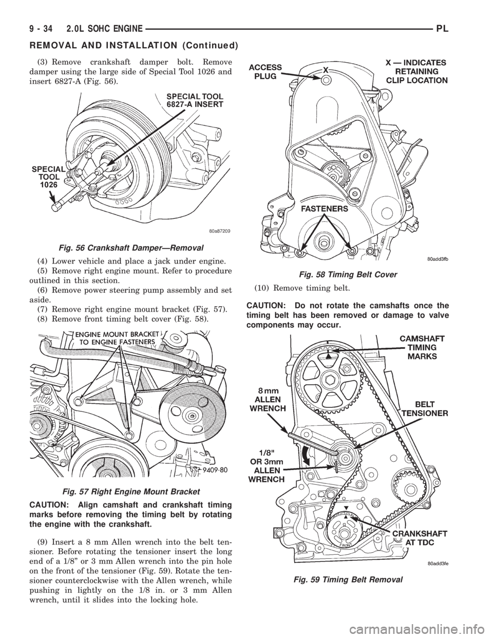
(3) Remove crankshaft damper bolt. Remove
damper using the large side of Special Tool 1026 and
insert 6827-A (Fig. 56).
(4) Lower vehicle and place a jack under engine.
(5) Remove right engine mount. Refer to procedure
outlined in this section.
(6) Remove power steering pump assembly and set
aside.
(7) Remove right engine mount bracket (Fig. 57).
(8) Remove front timing belt cover (Fig. 58).
CAUTION: Align camshaft and crankshaft timing
marks before removing the timing belt by rotating
the engine with the crankshaft.
(9) Inserta8mmAllen wrench into the belt ten-
sioner. Before rotating the tensioner insert the long
end of a 1/8º or 3 mm Allen wrench into the pin hole
on the front of the tensioner (Fig. 59). Rotate the ten-
sioner counterclockwise with the Allen wrench, while
pushing in lightly on the 1/8 in. or 3 mm Allen
wrench, until it slides into the locking hole.(10) Remove timing belt.
CAUTION: Do not rotate the camshafts once the
timing belt has been removed or damage to valve
components may occur.
Fig. 56 Crankshaft DamperÐRemoval
Fig. 57 Right Engine Mount Bracket
Fig. 58 Timing Belt Cover
Fig. 59 Timing Belt Removal
9 - 34 2.0L SOHC ENGINEPL
REMOVAL AND INSTALLATION (Continued)
Page 789 of 1200
(8) Align camshaft timing marks. Loosen timing
belt tensioner fasteners and remove timing belt.
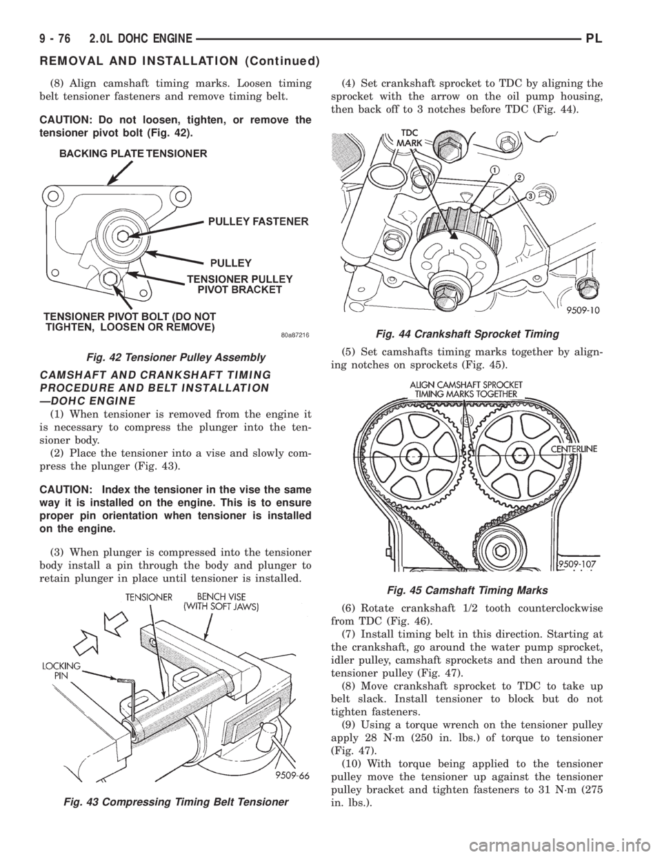
CAUTION: Do not loosen, tighten, or remove the
tensioner pivot bolt (Fig. 42).
CAMSHAFT AND CRANKSHAFT TIMING
PROCEDURE AND BELT INSTALLATION
ÐDOHC ENGINE
(1) When tensioner is removed from the engine it
is necessary to compress the plunger into the ten-
sioner body.
(2) Place the tensioner into a vise and slowly com-
press the plunger (Fig. 43).
CAUTION: Index the tensioner in the vise the same
way it is installed on the engine. This is to ensure
proper pin orientation when tensioner is installed
on the engine.
(3) When plunger is compressed into the tensioner
body install a pin through the body and plunger to
retain plunger in place until tensioner is installed.(4) Set crankshaft sprocket to TDC by aligning the
sprocket with the arrow on the oil pump housing,
then back off to 3 notches before TDC (Fig. 44).
(5) Set camshafts timing marks together by align-
ing notches on sprockets (Fig. 45).
(6) Rotate crankshaft 1/2 tooth counterclockwise
from TDC (Fig. 46).
(7) Install timing belt in this direction. Starting at
the crankshaft, go around the water pump sprocket,
idler pulley, camshaft sprockets and then around the
tensioner pulley (Fig. 47).
(8) Move crankshaft sprocket to TDC to take up
belt slack. Install tensioner to block but do not
tighten fasteners.
(9) Using a torque wrench on the tensioner pulley
apply 28 N´m (250 in. lbs.) of torque to tensioner
(Fig. 47).
(10) With torque being applied to the tensioner
pulley move the tensioner up against the tensioner
pulley bracket and tighten fasteners to 31 N´m (275
in. lbs.).
Fig. 42 Tensioner Pulley Assembly
Fig. 43 Compressing Timing Belt Tensioner
Fig. 44 Crankshaft Sprocket Timing
Fig. 45 Camshaft Timing Marks
9 - 76 2.0L DOHC ENGINEPL
REMOVAL AND INSTALLATION (Continued)
Page 792 of 1200
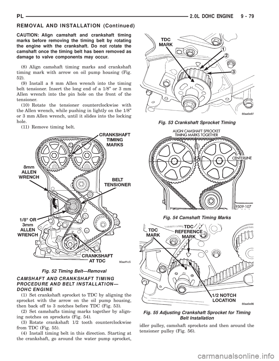
CAUTION: Align camshaft and crankshaft timing
marks before removing the timing belt by rotating
the engine with the crankshaft. Do not rotate the
camshaft once the timing belt has been removed as
damage to valve components may occur.
(8) Align camshaft timing marks and crankshaft
timing mark with arrow on oil pump housing (Fig.
52).
(9) Installa8mmAllen wrench into the timing
belt tensioner. Insert the long end of a 1/8º or 3 mm
Allen wrench into the pin hole on the front of the
tensioner.
(10) Rotate the tensioner counterclockwise with
the Allen wrench, while pushing in lightly on the 1/8º
or 3 mm Allen wrench, until it slides into the locking
hole.
(11) Remove timing belt.
CAMSHAFT AND CRANKSHAFT TIMING
PROCEDURE AND BELT INSTALLATIONÐ
DOHC ENGINE
(1) Set crankshaft sprocket to TDC by aligning the
sprocket with the arrow on the oil pump housing,
then back off to 3 notches before TDC (Fig. 53).
(2) Set camshafts timing marks together by align-
ing notches on sprockets (Fig. 54).
(3) Rotate crankshaft 1/2 tooth counterclockwise
from TDC (Fig. 55).
(4) Install timing belt in this direction. Starting at
the crankshaft, go around the water pump sprocket,idler pulley, camshaft sprockets and then around the
tensioner pulley (Fig. 56).
Fig. 52 Timing BeltÐRemoval
Fig. 53 Crankshaft Sprocket Timing
Fig. 54 Camshaft Timing Marks
Fig. 55 Adjusting Crankshaft Sprocket for Timing
Belt Installation
PL2.0L DOHC ENGINE 9 - 79
REMOVAL AND INSTALLATION (Continued)