DODGE NEON 2000 Service Repair Manual
Manufacturer: DODGE, Model Year: 2000, Model line: NEON, Model: DODGE NEON 2000Pages: 1285, PDF Size: 29.42 MB
Page 1081 of 1285
pilot hole and bolt circle of the wheel should be the
same as the original wheel.
WARNING: FAILURE TO USE EQUIVALENT
REPLACEMENT WHEELS MAY ADVERSELY AFFECT
THE SAFETY AND HANDLING OF THE VEHICLE.
USED WHEELS ARE NOT RECOMMENDED. THE
SERVICE HISTORY OF THE WHEEL MAY HAVE
INCLUDED SEVERE TREATMENT OR VERY HIGH
MILEAGE. THE RIM COULD FAIL WITHOUT WARN-
ING.
TIRE AND WHEEL RUNOUT
NOTE: Runout should always be measured off the
vehicle and on a suitable balance machine.
Radial run out is the difference between the high
and low points on the outer edge of the tire or wheel.
Lateral run out is the total side±to±side wobble of
the tire or wheel.
Radial run out of more than 1.5 mm (.060 inch)
measured at the center line of the tread may cause
the vehicle to shake.
Lateral run out of more than 2.0 mm (.080 inch)
measured at the side of the tire as close to the tread
as possible may cause the vehicle to shake.
Sometimes radial run out can be reduced by relo-
cating the wheel and tire on the wheel studs (See
Method 1). If this does not reduce run out to an
acceptable level, the tire can be rotated on the wheel.
(See Method 2).
METHOD 1 (RELOCATE WHEEL ON HUB)
Check accuracy of the wheel mounting surface;
adjust wheel bearings.
Drive vehicle a short distance to eliminate tire flat
spotting from a parked position.
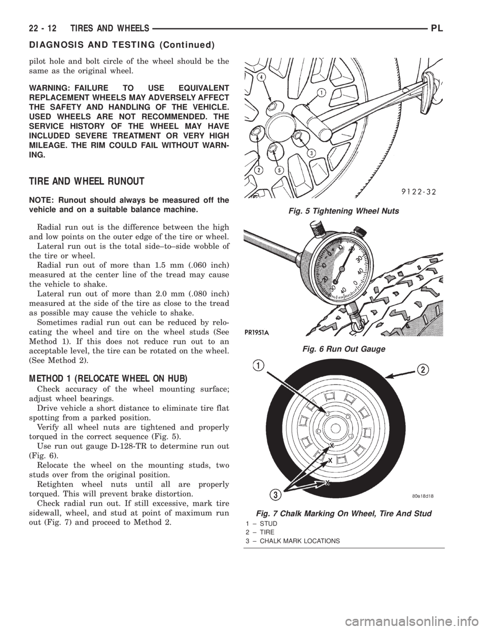
Verify all wheel nuts are tightened and properly
torqued in the correct sequence (Fig. 5).
Use run out gauge D-128-TR to determine run out
(Fig. 6).
Relocate the wheel on the mounting studs, two
studs over from the original position.
Retighten wheel nuts until all are properly
torqued. This will prevent brake distortion.
Check radial run out. If still excessive, mark tire
sidewall, wheel, and stud at point of maximum run
out (Fig. 7) and proceed to Method 2.
Fig. 5 Tightening Wheel Nuts
Fig. 6 Run Out Gauge
Fig. 7 Chalk Marking On Wheel, Tire And Stud
1 ± STUD
2 ± TIRE
3 ± CHALK MARK LOCATIONS
22 - 12 TIRES AND WHEELSPL
DIAGNOSIS AND TESTING (Continued)
Page 1082 of 1285
METHOD 2 (RELOCATE TIRE ON WHEEL)
Rotating tire on wheel is particularly effective
when there is run out in both tire and wheel.
Remove tire from wheel and remount wheel on hub
in former position.
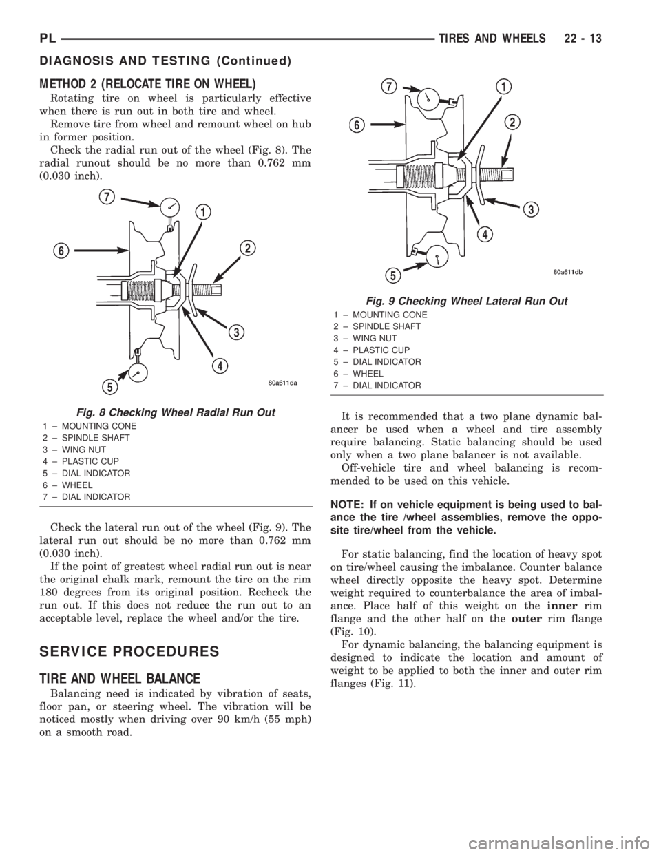
Check the radial run out of the wheel (Fig. 8). The
radial runout should be no more than 0.762 mm
(0.030 inch).
Check the lateral run out of the wheel (Fig. 9). The
lateral run out should be no more than 0.762 mm
(0.030 inch).
If the point of greatest wheel radial run out is near
the original chalk mark, remount the tire on the rim
180 degrees from its original position. Recheck the
run out. If this does not reduce the run out to an
acceptable level, replace the wheel and/or the tire.
SERVICE PROCEDURES
TIRE AND WHEEL BALANCE
Balancing need is indicated by vibration of seats,
floor pan, or steering wheel. The vibration will be
noticed mostly when driving over 90 km/h (55 mph)
on a smooth road.It is recommended that a two plane dynamic bal-
ancer be used when a wheel and tire assembly
require balancing. Static balancing should be used
only when a two plane balancer is not available.
Off-vehicle tire and wheel balancing is recom-
mended to be used on this vehicle.
NOTE: If on vehicle equipment is being used to bal-
ance the tire /wheel assemblies, remove the oppo-
site tire/wheel from the vehicle.
For static balancing, find the location of heavy spot
on tire/wheel causing the imbalance. Counter balance
wheel directly opposite the heavy spot. Determine
weight required to counterbalance the area of imbal-
ance. Place half of this weight on theinnerrim
flange and the other half on theouterrim flange
(Fig. 10).
For dynamic balancing, the balancing equipment is
designed to indicate the location and amount of
weight to be applied to both the inner and outer rim
flanges (Fig. 11).
Fig. 8 Checking Wheel Radial Run Out
1 ± MOUNTING CONE
2 ± SPINDLE SHAFT
3 ± WING NUT
4 ± PLASTIC CUP
5 ± DIAL INDICATOR
6 ± WHEEL
7 ± DIAL INDICATOR
Fig. 9 Checking Wheel Lateral Run Out
1 ± MOUNTING CONE
2 ± SPINDLE SHAFT
3 ± WING NUT
4 ± PLASTIC CUP
5 ± DIAL INDICATOR
6 ± WHEEL
7 ± DIAL INDICATOR
PLTIRES AND WHEELS 22 - 13
DIAGNOSIS AND TESTING (Continued)
Page 1083 of 1285
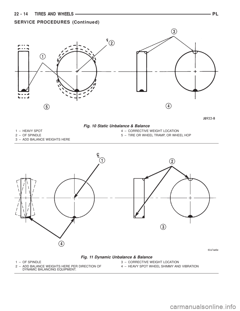
Fig. 10 Static Unbalance & Balance
1 ± HEAVY SPOT
2 ± OF SPINDLE
3 ± ADD BALANCE WEIGHTS HERE4 ± CORRECTIVE WEIGHT LOCATION
5 ± TIRE OR WHEEL TRAMP, OR WHEEL HOP
Fig. 11 Dynamic Unbalance & Balance
1 ± OF SPINDLE
2 ± ADD BALANCE WEIGHTS HERE PER DIRECTION OF
DYNAMIC BALANCING EQUIPMENT.3 ± CORRECTIVE WEIGHT LOCATION
4 ± HEAVY SPOT WHEEL SHIMMY AND VIBRATION
22 - 14 TIRES AND WHEELSPL
SERVICE PROCEDURES (Continued)
Page 1084 of 1285
REMOVAL AND INSTALLATION
WHEEL COVER (LOCK-ON)
REMOVE
NOTE: When unthreading the wheel cover retaining
nuts (Fig. 12) from the wheel nuts it is recom-
mended that a hand wrench be used and not an
impact wrench. Use of an impact wrench could
result in damage to the lock-on wheel cover retain-
ing nuts.
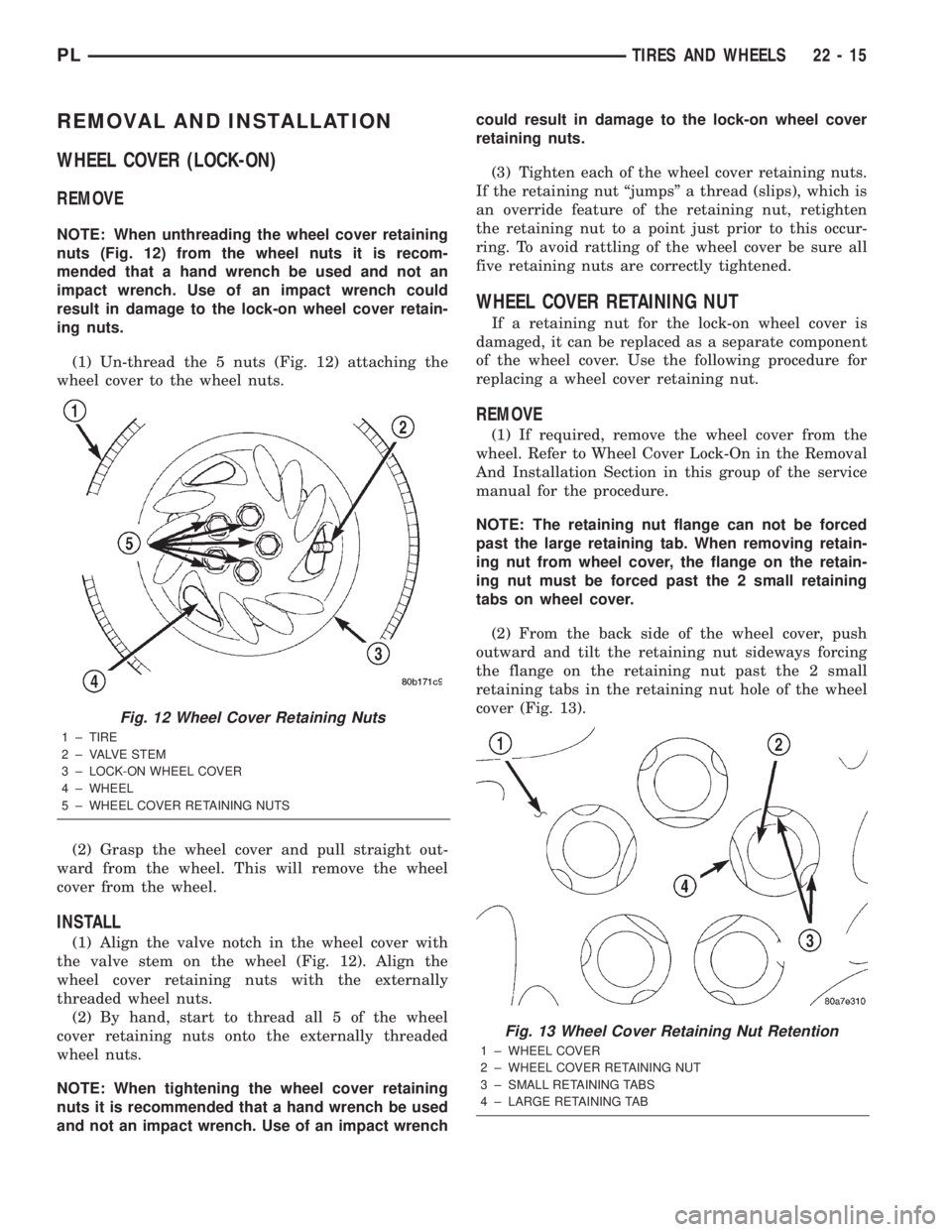
(1) Un-thread the 5 nuts (Fig. 12) attaching the
wheel cover to the wheel nuts.
(2) Grasp the wheel cover and pull straight out-
ward from the wheel. This will remove the wheel
cover from the wheel.
INSTALL
(1) Align the valve notch in the wheel cover with
the valve stem on the wheel (Fig. 12). Align the
wheel cover retaining nuts with the externally
threaded wheel nuts.
(2) By hand, start to thread all 5 of the wheel
cover retaining nuts onto the externally threaded
wheel nuts.
NOTE: When tightening the wheel cover retaining
nuts it is recommended that a hand wrench be used
and not an impact wrench. Use of an impact wrenchcould result in damage to the lock-on wheel cover
retaining nuts.
(3) Tighten each of the wheel cover retaining nuts.
If the retaining nut ªjumpsº a thread (slips), which is
an override feature of the retaining nut, retighten
the retaining nut to a point just prior to this occur-
ring. To avoid rattling of the wheel cover be sure all
five retaining nuts are correctly tightened.
WHEEL COVER RETAINING NUT
If a retaining nut for the lock-on wheel cover is
damaged, it can be replaced as a separate component
of the wheel cover. Use the following procedure for
replacing a wheel cover retaining nut.
REMOVE
(1) If required, remove the wheel cover from the
wheel. Refer to Wheel Cover Lock-On in the Removal
And Installation Section in this group of the service
manual for the procedure.
NOTE: The retaining nut flange can not be forced
past the large retaining tab. When removing retain-
ing nut from wheel cover, the flange on the retain-
ing nut must be forced past the 2 small retaining
tabs on wheel cover.
(2) From the back side of the wheel cover, push
outward and tilt the retaining nut sideways forcing
the flange on the retaining nut past the 2 small
retaining tabs in the retaining nut hole of the wheel
cover (Fig. 13).
Fig. 12 Wheel Cover Retaining Nuts
1 ± TIRE
2 ± VALVE STEM
3 ± LOCK-ON WHEEL COVER
4 ± WHEEL
5 ± WHEEL COVER RETAINING NUTS
Fig. 13 Wheel Cover Retaining Nut Retention
1 ± WHEEL COVER
2 ± WHEEL COVER RETAINING NUT
3 ± SMALL RETAINING TABS
4 ± LARGE RETAINING TAB
PLTIRES AND WHEELS 22 - 15
Page 1085 of 1285
(3) When flange on retaining nut is past the 2
retaining tabs on the wheel cover, remove retaining
nut from wheel cover by pushing or pulling from hole
in wheel cover.
INSTALL
(1) Install retaining nut in hole of wheel cover
with retaining nut flange positioned under the large
retaining flange (Fig. 13).
(2) Push on hex of retaining nut forcing the retain-
ing nut flange past the 2 small retaining tabs in
wheel cover.
TIRE AND WHEEL ASSEMBLY
CAST WHEEL
REMOVAL
(1) Raise the vehicle. Refer to HOISTING in the
LUBRICATION AND MAINTENANCE section.
(2) Remove the wheel mounting nuts from the
studs.
(3) Remove the tire and wheel assembly from the
hub.
INSTALLATION
CAUTION: Installing the wheel mounting nuts with-
out having good metal-to-mental contact between
the back of the wheel and the hub mounted brake
disc or drum could cause the wheel to bind and
eventually cause loosening of the wheel mounting
nuts.
(1) Install the tire and wheel assembly on the hub
studs against the hub mounted brake disc or drum
using the hub pilot as a guide.
CAUTION: When installing the tire and wheel
assembly, never use oil or grease on studs or nuts.
(2) Install and lightly tighten the wheel mounting
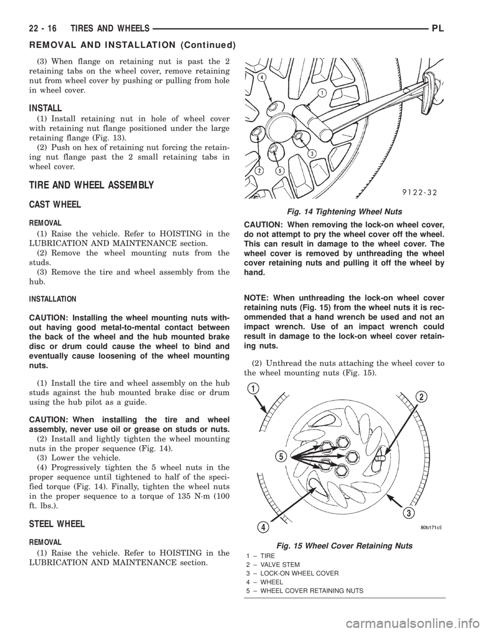
nuts in the proper sequence (Fig. 14).
(3) Lower the vehicle.
(4) Progressively tighten the 5 wheel nuts in the
proper sequence until tightened to half of the speci-
fied torque (Fig. 14). Finally, tighten the wheel nuts
in the proper sequence to a torque of 135 N´m (100
ft. lbs.).
STEEL WHEEL
REMOVAL
(1) Raise the vehicle. Refer to HOISTING in the
LUBRICATION AND MAINTENANCE section.CAUTION: When removing the lock-on wheel cover,
do not attempt to pry the wheel cover off the wheel.
This can result in damage to the wheel cover. The
wheel cover is removed by unthreading the wheel
cover retaining nuts and pulling it off the wheel by
hand.
NOTE: When unthreading the lock-on wheel cover
retaining nuts (Fig. 15) from the wheel nuts it is rec-
ommended that a hand wrench be used and not an
impact wrench. Use of an impact wrench could
result in damage to the lock-on wheel cover retain-
ing nuts.
(2) Unthread the nuts attaching the wheel cover to
the wheel mounting nuts (Fig. 15).
Fig. 14 Tightening Wheel Nuts
Fig. 15 Wheel Cover Retaining Nuts
1 ± TIRE
2 ± VALVE STEM
3 ± LOCK-ON WHEEL COVER
4 ± WHEEL
5 ± WHEEL COVER RETAINING NUTS
22 - 16 TIRES AND WHEELSPL
REMOVAL AND INSTALLATION (Continued)
Page 1086 of 1285
(3) Grasp the wheel cover and pull straight out-
ward. This will remove the wheel cover from the
wheel.
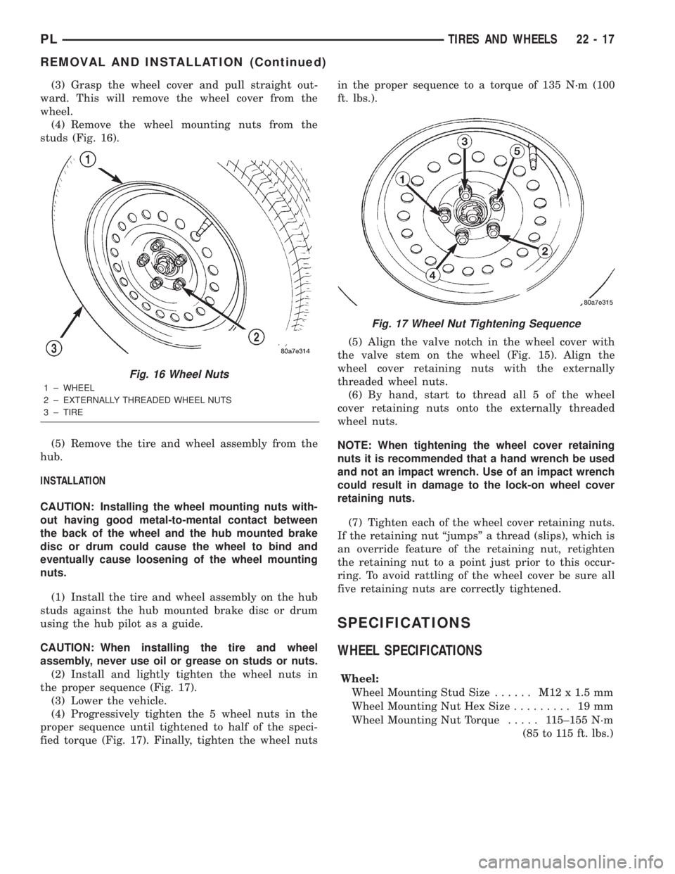
(4) Remove the wheel mounting nuts from the
studs (Fig. 16).
(5) Remove the tire and wheel assembly from the
hub.
INSTALLATION
CAUTION: Installing the wheel mounting nuts with-
out having good metal-to-mental contact between
the back of the wheel and the hub mounted brake
disc or drum could cause the wheel to bind and
eventually cause loosening of the wheel mounting
nuts.
(1) Install the tire and wheel assembly on the hub
studs against the hub mounted brake disc or drum
using the hub pilot as a guide.
CAUTION: When installing the tire and wheel
assembly, never use oil or grease on studs or nuts.
(2) Install and lightly tighten the wheel nuts in
the proper sequence (Fig. 17).
(3) Lower the vehicle.
(4) Progressively tighten the 5 wheel nuts in the
proper sequence until tightened to half of the speci-
fied torque (Fig. 17). Finally, tighten the wheel nutsin the proper sequence to a torque of 135 N´m (100
ft. lbs.).
(5) Align the valve notch in the wheel cover with
the valve stem on the wheel (Fig. 15). Align the
wheel cover retaining nuts with the externally
threaded wheel nuts.
(6) By hand, start to thread all 5 of the wheel
cover retaining nuts onto the externally threaded
wheel nuts.
NOTE: When tightening the wheel cover retaining
nuts it is recommended that a hand wrench be used
and not an impact wrench. Use of an impact wrench
could result in damage to the lock-on wheel cover
retaining nuts.
(7) Tighten each of the wheel cover retaining nuts.
If the retaining nut ªjumpsº a thread (slips), which is
an override feature of the retaining nut, retighten
the retaining nut to a point just prior to this occur-
ring. To avoid rattling of the wheel cover be sure all
five retaining nuts are correctly tightened.
SPECIFICATIONS
WHEEL SPECIFICATIONS
Wheel:
Wheel Mounting Stud Size...... M12x1.5mm
Wheel Mounting Nut Hex Size......... 19mm
Wheel Mounting Nut Torque..... 115±155 N´m
(85 to 115 ft. lbs.)
Fig. 16 Wheel Nuts
1 ± WHEEL
2 ± EXTERNALLY THREADED WHEEL NUTS
3 ± TIRE
Fig. 17 Wheel Nut Tightening Sequence
PLTIRES AND WHEELS 22 - 17
REMOVAL AND INSTALLATION (Continued)
Page 1087 of 1285

Page 1088 of 1285
EMISSION CONTROL SYSTEMS
TABLE OF CONTENTS
page page
ON-BOARD DIAGNOSTICS................... 1 EVAPORATIVE EMISSION CONTROLS......... 25
ON-BOARD DIAGNOSTICS
TABLE OF CONTENTS
page page
DESCRIPTION AND OPERATION
SYSTEM DESCRIPTION....................1
TASK MANAGER..........................2
MALFUNCTION INDICATOR LAMP (MIL)........5
DRB III STATE DISPLAY TEST MODE..........5
DRB III CIRCUIT ACTUATION TEST MODE......5
DIAGNOSTIC TROUBLE CODES..............5
DIAGNOSTIC TROUBLE CODE
DESCRIPTIONS.........................6MONITORED SYSTEMS....................15
TRIP DEFINITION........................19
MONITORED COMPONENT.................19
NON-MONITORED CIRCUITS...............23
HIGH AND LOW LIMITS....................24
LOAD VALUE............................24
DESCRIPTION AND OPERATION
SYSTEM DESCRIPTION
DESCRIPTION
OBD II requires that vehicles falling under OBD II
guidelines utilize the following system monitors:
²Comprehensive Component Monitor (inputs/out-
puts for powertrain management that affect emis-
sions, but do not have a specific major monitor)
²Fuel Control Monitor (fuel compensation
required to maintain stoichiometric ratio rich/lean)
²Misfire Monitor (change in crankshaft speed)
²Oxygen Sensor Heater Monitor (response and
performance of oxygen sensors)
²Catalyst Monitor (Performance and efficiency of
catalyst)
²Evaporative Emissions Monitor (performance of
and leaks from EVAP system)
²Exhaust Gas Recirculation Monitor (flow perfor-
mance of EGR system)
The software was rewritten to enable the PCM to
carry out the responsibilities to meet these required
guidelines. The PCM now contains a Task Manager.
OPERATION
The Powertrain Control Module (PCM) monitors
many different circuits in the fuel injection, ignition,
emission and engine systems. If the PCM senses a
problem with a monitored circuit often enough to
indicate an actual problem, it stores a Diagnostic
Trouble Code (DTC) in the PCM's memory. If the
code applies to a non-emissions related component or
system, and the problem is repaired or ceases to
exist, the PCM cancels the code after 40 warmup
cycles. Diagnostic trouble codes that affect vehicle
emissions illuminate the Malfunction Indicator Lamp
(MIL). Refer to Malfunction Indicator Lamp in this
section.
Certain criteria must be met before the PCM
stores a DTC in memory. The criteria may be a spe-
cific range of engine RPM, engine temperature,
and/or input voltage to the PCM.
The PCM might not store a DTC for a monitored
circuit even though a malfunction has occurred. This
may happen because one of the DTC criteria for the
circuit has not been met.For example, assume the
diagnostic trouble code criteria requires the PCM to
monitor the circuit only when the engine operates
between 750 and 2000 RPM. Suppose the sensor's
output circuit shorts to ground when engine operates
above 2400 RPM (resulting in 0 volt input to the
PLEMISSION CONTROL SYSTEMS 25 - 1
Page 1089 of 1285
PCM). Because the condition happens at an engine
speed above the maximum threshold (2000 rpm), the
PCM will not store a DTC.
There are several operating conditions for which
the PCM monitors and sets DTC's. Refer to Moni-
tored Systems, Components, and Non-Monitored Cir-
cuits in this section.
NOTE: Various diagnostic procedures may actually
cause a diagnostic monitor to set a DTC. For
instance, pulling a spark plug wire to perform a
spark test may set the misfire code. When a repair
is completed and verified, use the DRB III scan tool
to erase all DTC's and extinguish the MIL.
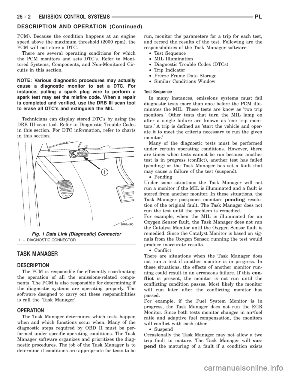
Technicians can display stored DTC's by using the
DRB III scan tool. Refer to Diagnostic Trouble Codes
in this section. For DTC information, refer to charts
in this section.
TASK MANAGER
DESCRIPTION
The PCM is responsible for efficiently coordinating
the operation of all the emissions-related compo-
nents. The PCM is also responsible for determining if
the diagnostic systems are operating properly. The
software designed to carry out these responsibilities
is call the 'Task Manager'.
OPERATION
The Task Manager determines which tests happen
when and which functions occur when. Many of the
diagnostic steps required by OBD II must be per-
formed under specific operating conditions. The Task
Manager software organizes and prioritizes the diag-
nostic procedures. The job of the Task Manager is to
determine if conditions are appropriate for tests to berun, monitor the parameters for a trip for each test,
and record the results of the test. Following are the
responsibilities of the Task Manager software:
²Test Sequence
²MIL Illumination
²Diagnostic Trouble Codes (DTCs)
²Trip Indicator
²Freeze Frame Data Storage
²Similar Conditions Window
Test Sequence
In many instances, emissions systems must fail
diagnostic tests more than once before the PCM illu-
minates the MIL. These tests are know as 'two trip
monitors.' Other tests that turn the MIL lamp on
after a single failure are known as 'one trip moni-
tors.' A trip is defined as 'start the vehicle and oper-
ate it to meet the criteria necessary to run the given
monitor.'
Many of the diagnostic tests must be performed
under certain operating conditions. However, there
are times when tests cannot be run because another
test is in progress (conflict), another test has failed
(pending) or the Task Manager has set a fault that
may cause a failure of the test (suspend).
²Pending
Under some situations the Task Manager will not
run a monitor if the MIL is illuminated and a fault is
stored from another monitor. In these situations, the
Task Manager postpones monitorspendingresolu-
tion of the original fault. The Task Manager does not
run the test until the problem is remedied.
For example, when the MIL is illuminated for an
Oxygen Sensor fault, the Task Manager does not run
the Catalyst Monitor until the Oxygen Sensor fault is
remedied. Since the Catalyst Monitor is based on sig-
nals from the Oxygen Sensor, running the test would
produce inaccurate results.
²Conflict
There are situations when the Task Manager does
not run a test if another monitor is in progress. In
these situations, the effects of another monitor run-
ning could result in an erroneous failure. If thiscon-
flictis present, the monitor is not run until the
conflicting condition passes. Most likely the monitor
will run later after the conflicting monitor has
passed.
For example, if the Fuel System Monitor is in
progress, the Task Manager does not run the EGR
Monitor. Since both tests monitor changes in air/fuel
ratio and adaptive fuel compensation, the monitors
will conflict with each other.
²Suspend
Occasionally the Task Manager may not allow a two
trip fault to mature. The Task Manager willsus-
pendthe maturing of a fault if a condition exists
Fig. 1 Data Link (Diagnostic) Connector
1 ± DIAGNOSTIC CONNECTOR
25 - 2 EMISSION CONTROL SYSTEMSPL
DESCRIPTION AND OPERATION (Continued)
Page 1090 of 1285
that may induce an erroneous failure. This prevents
illuminating the MIL for the wrong fault and allows
more precis diagnosis.
For example, if the PCM is storing a one trip fault
for the Oxygen Sensor and the EGR monitor, the
Task Manager may still run the EGR Monitor but
will suspend the results until the Oxygen Sensor
Monitor either passes or fails. At that point the Task
Manager can determine if the EGR system is actu-
ally failing or if an Oxygen Sensor is failing.
MIL Illumination
The PCM Task Manager carries out the illumina-
tion of the MIL. The Task Manager triggers MIL illu-
mination upon test failure, depending on monitor
failure criteria.
The Task Manager Screen shows both a Requested
MIL state and an Actual MIL state. When the MIL is
illuminated upon completion of a test for a third trip,
the Requested MIL state changes to OFF. However,
the MIL remains illuminated until the next key
cycle. (On some vehicles, the MIL will actually turn
OFF during the third key cycle) During the key cycle
for the third good trip, the Requested MIL state is
OFF, while the Actual MILL state is ON. After the
next key cycle, the MIL is not illuminated and both
MIL states read OFF.
Diagnostic Trouble Codes (DTCs)
With OBD II, different DTC faults have different
priorities according to regulations. As a result, the
priorities determine MIL illumination and DTC era-
sure. DTCs are entered according to individual prior-
ity. DTCs with a higher priority overwrite lower
priority DTCs.
Priorities
²Priority 0 ÐNon-emissions related trouble codes
²Priority 1 Ð One trip failure of a two trip fault
for non-fuel system and non-misfire.
²Priority 2 Ð One trip failure of a two trip fault
for fuel system (rich/lean) or misfire.
²Priority3ÐTwotrip failure for a non-fuel sys-
tem and non-misfire or matured one trip comprehen-
sive component fault.
²Priority4ÐTwotrip failure or matured fault
for fuel system (rich/lean) and misfire or one trip cat-
alyst damaging misfire.
Non-emissions related failures have no priority.
One trip failures of two trip faults have low priority.
Two trip failures or matured faults have higher pri-
ority. One and two trip failures of fuel system and
misfire monitor take precedence over non-fuel system
and non-misfire failures.DTC Self Erasure
With one trip components or systems, the MIL is
illuminated upon test failure and DTCs are stored.
Two trip monitors are components requiring failure
in two consecutive trips for MIL illumination. Upon
failure of the first test, the Task Manager enters a
maturing code. If the component fails the test for a
second time the code matures and a DTC is set.
After three good trips the MIL is extinguished and
the Task Manager automatically switches the trip
counter to a warm-up cycle counter. DTCs are auto-
matically erased following 40 warm-up cycles if the
component does not fail again.
For misfire and fuel system monitors, the compo-
nent must pass the test under a Similar Conditions
Window in order to record a good trip. A Similar Con-
ditions Window is when engine RPM is within6375
RPM and load is within610% of when the fault
occurred.
NOTE: It is important to understand that a compo-
nent does not have to fail under a similar window of
operation to mature. It must pass the test under a
Similar Conditions Window when it failed to record
a Good Trip for DTC erasure for misfire and fuel
system monitors.
DTCs can be erased anytime with a DRB III. Eras-
ing the DTC with the DRB III erases all OBD II
information. The DRB III automatically displays a
warning that erasing the DTC will also erase all
OBD II monitor data. This includes all counter infor-
mation for warm-up cycles, trips and Freeze Frame.
Trip Indicator
TheTripis essential for running monitors and
extinguishing the MIL. In OBD II terms, a trip is a
set of vehicle operating conditions that must be met
for a specific monitor to run. All trips begin with a
key cycle.
Good Trip
The Good Trip counters are as follows:
²Global Good Trip
²Fuel System Good Trip
²Misfire Good Trip
²Alternate Good Trip (appears as a Global Good
Trip on DRB III)
²Comprehensive Components
²Major Monitor
²Warm-Up Cycles
Global Good Trip
To increment a Global Good Trip, the Oxygen sen-
sor and Catalyst efficiency monitors must have run
and passed.
Fuel System Good Trip
To count a good trip (three required) and turn off
the MIL, the following conditions must occur:
PLEMISSION CONTROL SYSTEMS 25 - 3
DESCRIPTION AND OPERATION (Continued)