glove box DODGE NEON 2000 Service Repair Manual
[x] Cancel search | Manufacturer: DODGE, Model Year: 2000, Model line: NEON, Model: DODGE NEON 2000Pages: 1285, PDF Size: 29.42 MB
Page 214 of 1285
be checked. To determine if a high current draw con-
dition exists first check the vehicle with a test lamp.
(1) Verify that all electrical accessories are OFF.
²Remove key from ignition switch
²Turn off all lights
²Trunk lid is closed
²Engine compartment hood lamp is disconnected
or lamp removed
²Map lamp on rear view mirror
²Glove box door is closed
²Sun visor vanity lights are OFF
²All doors are closed
²Allow the ignition key lamp system to time out
in approximately 30 seconds, if equipped.
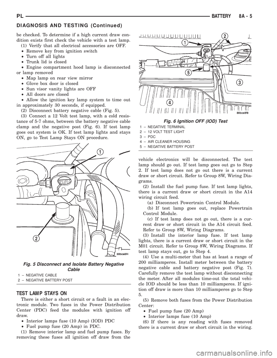
(2) Disconnect battery negative cable (Fig. 5).
(3) Connect a 12 Volt test lamp, with a cold resis-
tance of 5-7 ohms, between the battery negative cable
clamp and the negative post (Fig. 6). If test lamp
goes out system is OK. If test lamp lights and stays
ON, go to Test Lamp Stays ON procedure.
TEST LAMP STAYS ON
There is either a short circuit or a fault in an elec-
tronic module. Two fuses in the Power Distribution
Center (PDC) feed the modules with ignition off
draw.
²Interior lamps fuse (10 Amp) (IOD) PDC
²Fuel pump fuse (20 Amp) in PDC.
(1) Remove interior lamp and fuel pump fuses. By
removing these fuses all ignition off draw from thevehicle electronics will be disconnected. The test
lamp should go out. If test lamp goes out go to Step
2. If test lamp does not go out there is a current
draw or short circuit. Refer to Group 8W, Wiring Dia-
grams.
(2) Install the fuel pump fuse. If test lamp lights,
there is a current draw or short circuit in the A14
wiring circuit feed.
(a) Disconnect Powertrain Control Module.
(b) If test lamp goes out, replace Powertrain
Control Module.
(c) If test lamp does not go out, there is a cur-
rent draw or short circuit in the A14 circuit feed.
Refer to Group 8W, Wiring Diagrams.
(3) Install the interior lamp fuse. If test lamp
lights, there is a current draw or short circuit in the
M01 circuit. Refer to Group 8W, Wiring Diagrams. If
test lamp stays out, go to Step 4.
(4) Use a multi-meter that has at least a range of
200 milliamperes. Install meter between the battery
negative cable and battery negative post (Fig. 7).
Carefully remove the test lamp without disconnecting
the meter. After all modules time-out the total vehi-
cle IOD should be less than 10 milliamperes. If igni-
tion off draw is more than 10 milliamperes go to Step
5.
(5) Remove both fuses from the Power Distribution
Center:
²Fuel pump fuse (20 Amp)
²Interior lamps fuse (10 Amp)
(6) If there is any reading with fuses removed
there is a current draw or short circuit in the wiring.
Fig. 5 Disconnect and Isolate Battery Negative
Cable
1 ± NEGATIVE CABLE
2 ± NEGATIVE BATTERY POST
Fig. 6 Ignition OFF (IOD) Test
1 ± NEGATIVE TERMINAL
2 ± 12 VOLT TEST LIGHT
3 ± PDC
4 ± AIR CLEANER HOUSING
5 ± NEGATIVE BATTERY POST
PLBATTERY 8A - 5
DIAGNOSIS AND TESTING (Continued)
Page 248 of 1285
INSTRUMENT PANEL SYSTEMS
TABLE OF CONTENTS
page page
GENERAL INFORMATION
INTRODUCTION..........................1
DESCRIPTION AND OPERATION
HEADLAMP SWITCH......................2
INSTRUMENT CLUSTER....................2
WARNING AND INDICATOR LAMPS..........2
DIAGNOSIS AND TESTING
AIRBAG WARNING SYSTEM................2
BRAKE SYSTEM WARNING LAMP TEST.......2
INSTRUMENT CLUSTER LAMPS.............2
LOW OIL PRESSURE WARNING LAMP TEST...3
MULTIPLE/INDIVIDUAL GAUGES
INOPERATIVE..........................4
SERVICE PROCEDURES
INSTRUMENT CLUSTER SELF-DIAGNOSTICS...4
REMOVAL AND INSTALLATION
ACCESSORY SWITCH/POWER OUTLET
BEZEL................................4CENTER CONSOLE FLOOD LAMP............5
CIGAR LIGHTER / POWER OUTLET
ASSEMBLY.............................5
GLOVE BOX DOOR/BIN....................6
GLOVE BOX DOOR/BIN....................6
GLOVE BOX SWITCH/LAMP.................6
INSTRUMENT CLUSTER....................6
INSTRUMENT CLUSTER BEZEL..............6
INSTRUMENT CLUSTER LAMPS.............7
INSTRUMENT PANEL ASSEMBLY............7
INSTRUMENT PANEL CENTER BEZEL........10
INSTRUMENT PANEL END CAPS............10
INSTRUMENT PANEL TOP COVER...........10
LOWER INSTRUMENT PANEL COVER........10
LOWER STORAGE BIN....................10
STEERING COLUMN SHROUDS.............11
GENERAL INFORMATION
INTRODUCTION
The purpose of the dash gauges and indicator
lamps is to keep the driver informed about the oper-
ating condition of the vehicle. If an abnormal condi-
tion occurs, the driver is informed by indicator lamp.
The driver can seek service before damage occurs.
Indicator lamps use ON/OFF switch functions for
operation, while gauges use a sending unit or sensor.
The Instrument Panel can be removed as an
assembly after a few part are removed to allow
access to the retaining bolts. There is one self-align-
ing bulkhead connector on the left underside of the
instrument panel replacing most of the main harness
connectors. Once removed, the instrument panel can
be serviced for replacement. Most of the parts of the
instrument panel can be replaced individually with-
out removing the complete instrument panel assem-
bly.
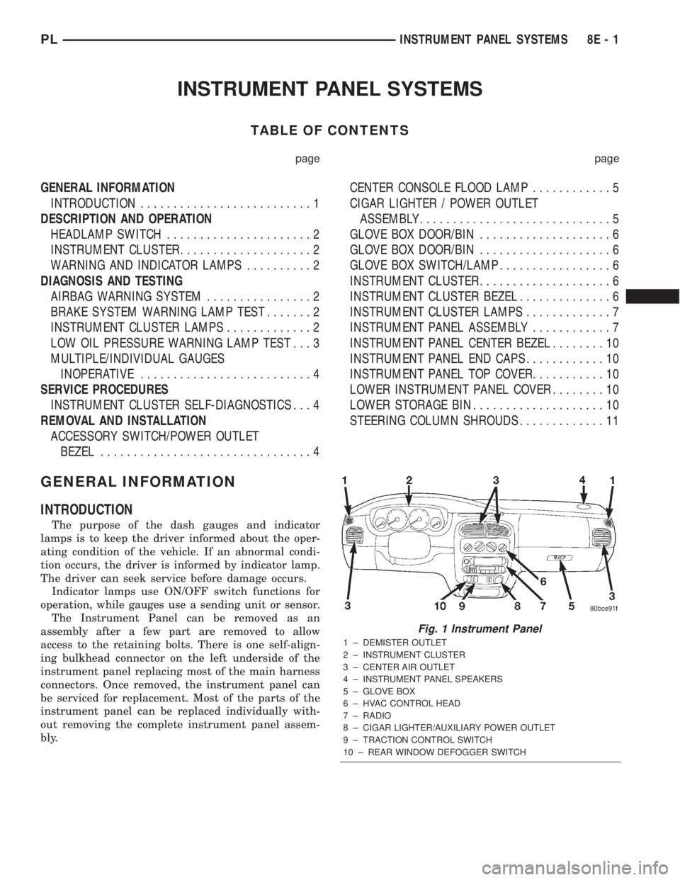
Fig. 1 Instrument Panel
1 ± DEMISTER OUTLET
2 ± INSTRUMENT CLUSTER
3 ± CENTER AIR OUTLET
4 ± INSTRUMENT PANEL SPEAKERS
5 ± GLOVE BOX
6 ± HVAC CONTROL HEAD
7 ± RADIO
8 ± CIGAR LIGHTER/AUXILIARY POWER OUTLET
9 ± TRACTION CONTROL SWITCH
10 ± REAR WINDOW DEFOGGER SWITCH
PLINSTRUMENT PANEL SYSTEMS 8E - 1
Page 253 of 1285
(6) Set base aside and remove base mount ring.
INSTALLATION
(1) Position mount ring to the instrument panel
and feed the wires through ring. Index the cap and
the mount ring with the index tab at 9 o'clock to the
key in the instrument panel. Install the ring.
(2) Connect wires to base. Orient base alignment
rib at 11 o'clock to mate the groove in mount ring at
the same location
(3) Push base into the bezel till it locks.
(4) Install cigar lighter cap and check operation of
element.
GLOVE BOX DOOR/BIN
REMOVAL
(1) Open front passenger door.
(2) Remove three glove box door hinge screws.
(3) Open glove box and remove assembly from
vehicle.
(4) Remove eight screws retaining glove box door
to bin assembly.
(5) Separate glove box door from bin and remove.
INSTALLATION
For installation, reverse the above procedures.
GLOVE BOX DOOR/BIN
REMOVAL
(1) Open front passenger door.
(2) Remove three glove box door hinge screws.
(3) Open glove box and remove assembly from
vehicle.
(4) Remove eight screws retaining glove box door
to bin assembly.(5) Separate glove box door from bin and remove.
INSTALLATION
For installation, reverse the above procedures.
GLOVE BOX SWITCH/LAMP
REMOVAL
(1) Disconnect and isolate the battery negative
cable (Fig. 6).
(2) Open the glove box and push the glove box
sides inward allowing the door bumpers to clear and
the box to tip forward.
(3) Reach inside the opening and squeeze the
lamp/switch retainers until they are disengage.
(4) Pull the switch/lamp rearward and remove it.
Replace the lamp. To replace the switch disconnect
wire and replace the switch.
INSTALLATION
For installation, reverse the above procedures.
INSTRUMENT CLUSTER
CAUTION: The Instrument Cluster MUST be stored
in a face up position or damage will occur to the
gauge operation.
REMOVAL
(1) Disconnect and isolate the battery negative
cable (Fig. 6).
(2) Remove both left and right A-Pillar trim covers.
(3) Remove the instrument panel top cover.
(4) Remove cluster bezel.
(5) Remove the four screws attaching cluster hous-
ing to the base panel.
(6) Pull the cluster rearward to disconnect from
base panel.
(7) Remove the cluster assembly.
INSTALLATION
For installation, reverse the above procedures.
INSTRUMENT CLUSTER BEZEL
REMOVAL
(1) Remove instrument panel top cover. Refer to
Instrument Panel Top Cover Removal and Installa-
tion in this section.
(2) Using a trim stick (special tool #C-4755), gently
pry up on the cluster bezel and remove from vehicle.
INSTALLATION
For installation, reverse the above procedures.
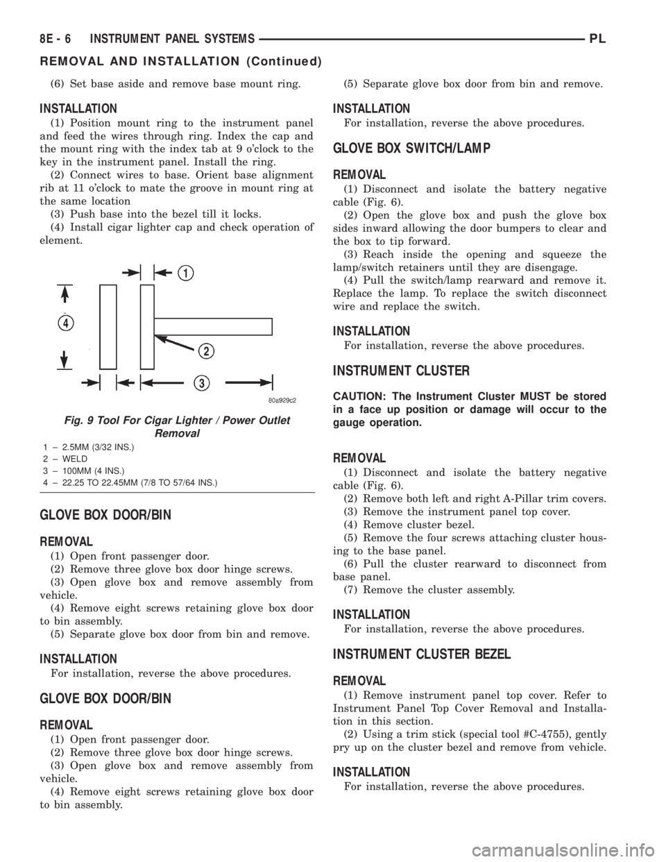
Fig. 9 Tool For Cigar Lighter / Power Outlet
Removal
1 ± 2.5MM (3/32 INS.)
2 ± WELD
3 ± 100MM (4 INS.)
4 ± 22.25 TO 22.45MM (7/8 TO 57/64 INS.)
8E - 6 INSTRUMENT PANEL SYSTEMSPL
REMOVAL AND INSTALLATION (Continued)
Page 256 of 1285
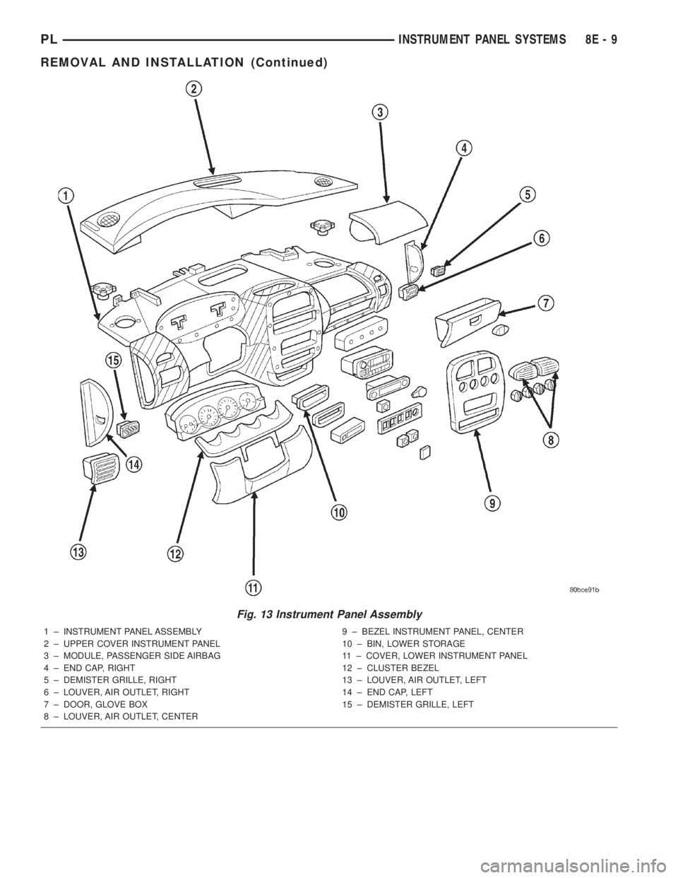
Fig. 13 Instrument Panel Assembly
1 ± INSTRUMENT PANEL ASSEMBLY
2 ± UPPER COVER INSTRUMENT PANEL
3 ± MODULE, PASSENGER SIDE AIRBAG
4 ± END CAP, RIGHT
5 ± DEMISTER GRILLE, RIGHT
6 ± LOUVER, AIR OUTLET, RIGHT
7 ± DOOR, GLOVE BOX
8 ± LOUVER, AIR OUTLET, CENTER9 ± BEZEL INSTRUMENT PANEL, CENTER
10 ± BIN, LOWER STORAGE
11 ± COVER, LOWER INSTRUMENT PANEL
12 ± CLUSTER BEZEL
13 ± LOUVER, AIR OUTLET, LEFT
14 ± END CAP, LEFT
15 ± DEMISTER GRILLE, LEFT
PLINSTRUMENT PANEL SYSTEMS 8E - 9
REMOVAL AND INSTALLATION (Continued)
Page 314 of 1285
LAMP BULB SERVICE
TABLE OF CONTENTS
page page
DESCRIPTION AND OPERATION
BULB...................................7
REMOVAL AND INSTALLATION
HEADLAMP BULB.........................7
FOG LAMP BULB..........................8
PARK AND TURN SIGNAL LAMP BULB.........8
FRONT SIDE MARKER LAMP BULB...........9
CENTER HIGH MOUNTED STOP LAMP BULB....9
TAIL, STOP, BACK-UP AND TURN SIGNAL
LAMP BULB............................9LICENSE PLATE LAMP BULB...............10
UNDERHOOD LAMP BULB.................10
REAR CARGO LAMP BULB.................10
DOME LAMP BULB.......................10
TRANSAXLE RANGE INDICATOR LAMP BULB . . 10
GLOVE BOX LAMP BULB...................11
FLOOR CONSOLE LAMP BULB..............11
VISOR VANITY LAMP BULB.................11
DESCRIPTION AND OPERATION
BULB
The electric light bulb is a source of electromag-
netic radiation which generates light. Vehicles use
many different types of bulbs:
²Headlamp bulb
²Fog Lamp bulb
²Tail Lamp bulb
²Stop Lamp bulb
²Turn Signal bulb
²Back up Lamp bulb
²Dome Lamp bulb
²Transaxle Range Indicator Lamp bulb (PRNDL)
²Glove Box Lamp bulb
²Floor Console Lamp bulb
²Rear Cargo Lamp bulb
²Visor Vanity Lamp bulb
²Underhood Lamp bulb
²etc.
REMOVAL AND INSTALLATION
HEADLAMP BULB
REMOVAL
(1) Release hood latch and open hood.
(2) Remove screws attaching headlamp module to
upper crossmember.
(3) Remove headlamp module from vehicle.
(4) Disconnect wire connector from back of head-
lamp bulb.
(5) Rotate retaining ring counterclockwise one
quarter turn.
(6) Remove retaining ring from headlamp module.
(7) Remove bulb from headlamp module (Fig. 1).
INSTALLATION
CAUTION: Do not touch the glass of halogen bulbs
with fingers or other possibly oily surface, reduced
bulb life will result.
(1) Install bulb into headlamp module.
(2) Install retaining ring to headlamp module.
(3) Rotate retaining ring clockwise one quarter
turn.
(4) Connect wire connector to the back of head-
lamp bulb.
(5) Place headlamp module in position.
(6) Install screws attaching headlamp module to
upper crossmember.
(7) Close hood.
PLLAMPS 8L - 7
Page 318 of 1285
INSTALLATION
(1) Push bulb in socket and snap into place.
(2) Install floor console.
GLOVE BOX LAMP BULB
REMOVAL
(1) Open glove box door.
(2) Pull downward on lamp/switch assembly to dis-
engage tabs from instrument panel.
(3) Pull bulb from socket.
INSTALLATION
(1) Push bulb into socket.
(2) Place lamp/switch assembly into position.
(3) Push lamp/switch assembly to lock tabs.
(4) Check lamp operation, and close glove door.
FLOOR CONSOLE LAMP BULB
REMOVAL
(1) Using a flat bladed tool, slide it between the
lamp and instrument panel to disengage tabs.(2) Remove bulb from lamp socket.
INSTALLATION
(1) Install bulb into socket.
(2) Place lamp into position.
(3) Push lamp to lock tabs.
(4) Check lamp operation.
VISOR VANITY LAMP BULB
REMOVAL
(1) Lower visor.
(2) Insert a small flat bladed tool between the
lamp lens and lamp.
(3) Carefully pry lens outward.
(4) Remove bulb from socket.
INSTALLATION
(1) Position bulb in socket and snap into place.
(2) Position lens on lamp and snap into place.
PLLAMPS 8L - 11
REMOVAL AND INSTALLATION (Continued)
Page 319 of 1285
LAMP SERVICE
TABLE OF CONTENTS
page page
DESCRIPTION AND OPERATION
LAMP ASSEMBLIES.......................12
REMOVAL AND INSTALLATION
HEADLAMP MODULE.....................12
FOG LAMP..............................13
PARK AND TURN SIGNAL LAMP BULB........13
FRONT SIDE MARKER LAMP...............13
CENTER HIGH MOUNTED STOP LAMP
(CHMSL)..............................14TAIL, STOP AND TURN SIGNAL LAMP........14
LICENSE PLATE LAMP....................14
UNDERHOOD LAMP......................14
REAR CARGO LAMP......................15
DOME LAMP............................15
GLOVE BOX LAMP BULB..................15
FLOOR CONSOLE LAMP BULB..............15
VISOR VANITY LAMP......................15
DESCRIPTION AND OPERATION
LAMP ASSEMBLIES
The lamp assemblies or modules generally consist
of a housing, reflector(s) and lens that directs a light
source. Vehicles use many different types of lamps:
²Headlamp
²Fog Lamp
²Tail Lamp
²Stop Lamp
²Turn Signal Lamp
²Back up Lamp
²Dome Lamp
²Transaxle Range Indicator Lamp (PRNDL)
²Glove Box Lamp
²Floor Console Lamp
²Rear Cargo Lamp
²Visor Vanity Lamp
²Underhood Lamp
²etc.
REMOVAL AND INSTALLATION
HEADLAMP MODULE
REMOVAL
(1) Release hood latch and open hood.
(2) Remove screws attaching headlamp module to
upper crossmember.
(3) Remove headlamp module from vehicle.
(4) Disconnect wire connectors from back of head-
lamp module.
(5) Remove headlamp module (Fig. 1).
INSTALLATION
CAUTION: Do not touch the glass of halogen bulbs
with fingers or other possibly oily surface, reduced
bulb life will result.
(1) Connect wire connectors to the back of head-
lamp module.
(2) Place headlamp module in position.
(3) Install screws attaching headlamp module to
upper crossmember.
(4) Close hood.
8L - 12 LAMPSPL
Page 322 of 1285
INSTALLATION
(1) Position lamp on hood and install screw.
(2) Connect lamp wire connector.
(3) Install lamp bulb.
(4) Install lens lamp.
(5) Close hood.
REAR CARGO LAMP
REMOVAL
(1) Insert a trim stick or small flat blade between
the lamp lens and rear shelf reinforcement panel.
(2) Pry the lamp lens downward.
(3) Disconnect wire connector.
(4) Remove lamp from vehicle.
INSTALLATION
(1) Place lamp into position.
(2) Connect wire connector.
(3) Install lamp lens.
DOME LAMP
REMOVAL
(1) Insert a trim stick between the dome lamp
bezel and dome lamp lens. Carefully pry down on one
side of the lamp lens.(2) Carefully pull down on lamp lens to remove
lamp from headliner.
(3) Disconnect wire connector.
(4) Remove lamp from vehicle.
INSTALLATION
(1) Place lamp into position.
(2) Connect wire connector.
(3) Install dome lamp and lens.
GLOVE BOX LAMP BULB
REMOVAL
(1) Open glove box door.
(2) Pull downward on lamp/switch assembly to dis-
engage tabs from instrument panel.
(3) Pull bulb from socket.
(4) Disconnect wire connector from lamp and
remove glove box lamp/switch.
INSTALLATION
(1) Push bulb into socket.
(2) Place lamp/switch assembly into position.
(3) Connect wire connector to the lamp/switch.
(4) Push lamp/switch assembly to lock tabs.
(5) Check lamp operation, and close glove door.
FLOOR CONSOLE LAMP BULB
REMOVAL
(1) Using a flat bladed tool, slide it between the
lamp and instrument panel to disengage tabs.
(2) Remove bulb from lamp socket.
INSTALLATION
(1) Install bulb into socket.
(2) Place lamp into position.
(3) Push lamp to lock tabs.
(4) Check lamp operation.
VISOR VANITY LAMP
The visor vanity lamp is incorporated in the visor
assembly. Replace the visor if the lamp has failed.
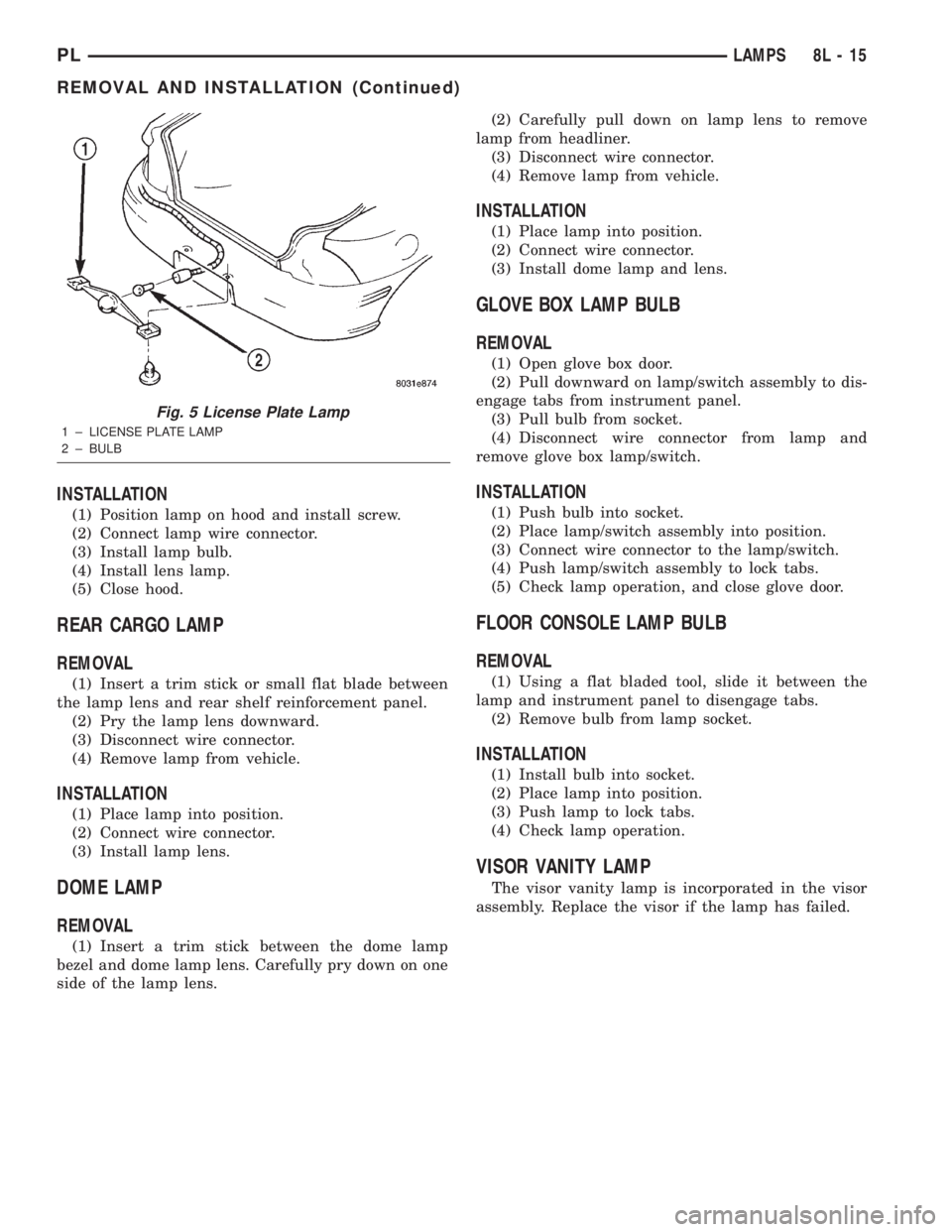
Fig. 5 License Plate Lamp
1 ± LICENSE PLATE LAMP
2 ± BULB
PLLAMPS 8L - 15
REMOVAL AND INSTALLATION (Continued)
Page 344 of 1285
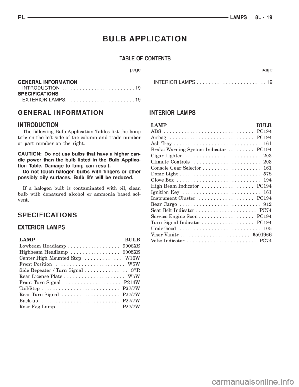
BULB APPLICATION
TABLE OF CONTENTS
page page
GENERAL INFORMATION
INTRODUCTION.........................19
SPECIFICATIONS
EXTERIOR LAMPS........................19INTERIOR LAMPS........................19
GENERAL INFORMATION
INTRODUCTION
The following Bulb Application Tables list the lamp
title on the left side of the column and trade number
or part number on the right.
CAUTION: Do not use bulbs that have a higher can-
dle power than the bulb listed in the Bulb Applica-
tion Table. Damage to lamp can result.
Do not touch halogen bulbs with fingers or other
possibly oily surfaces. Bulb life will be reduced.
If a halogen bulb is contaminated with oil, clean
bulb with denatured alcohol or ammonia based sol-
vent.
SPECIFICATIONS
EXTERIOR LAMPS
LAMP BULB
Lowbeam Headlamp..................9006XS
Highbeam Headlamp.................9005XS
Center High Mounted Stop.............W16W
Front Position........................ W5W
Side Repeater / Turn Signal............... 37R
Rear License Plate..................... W5W
Front Turn Signal....................P214W
Tail/Stop...........................P27/7W
Rear Turn Signal....................P27/7W
Back-up...........................P27/7W
Rear Fog Lamp......................P27/7W
INTERIOR LAMPS
LAMP BULB
ABS ...............................PC194
Airbag.............................PC194
AshTray .............................. 161
Brake Warning System Indicator.........PC194
Cigar Lighter.......................... 203
Climate Controls........................ 203
Console Gear Selector.................... 161
Dome Light............................ 578
Glove Box............................. 194
High Beam Indicator..................PC194
Ignition Key........................... 161
Instrument Cluster...................PC194
Rear Cargo............................ 912
Seat Belt Indicator.....................PC74
Service Engine Soon...................PC194
Turn Signal Indicator..................PC194
Underhood............................ 105
Visor Vanity........................6501966
Volts Indicator........................PC74
PLLAMPS 8L - 19
Page 352 of 1285
PASSENGER AIRBAG MODULE
WARNING: DISCONNECT AND ISOLATE THE BAT-
TERY NEGATIVE (GROUND) CABLE BEFORE
BEGINNING ANY AIRBAG SYSTEM COMPONENT
REMOVAL OR INSTALLATION PROCEDURE. THIS
WILL DISABLE THE AIRBAG SYSTEM. FAILURE TO
DISCONNECT BATTERY COULD RESULT IN ACCI-
DENTAL AIRBAG DEPLOYMENT AND POSSIBLE
PERSONAL INJURY.
ALLOW SYSTEM CAPACITOR TO DISCHARGE
FOR 1 MINUTE BEFORE REMOVING ANY AIRBAG
COMPONENTS.
NON-DEPLOYED MODULE
REMOVAL
When removing a module for any reason other
than DEPLOYMENT.
(1) Disconnect and isolate the battery negative
cable (Fig. 4).
(2) Wait one minute for the reserve capacitor to
discharge before removing non-deployed module.
(3) Remove instrument panel top cover. Refer to
Group 8E Instrument Panel Systems, Instrument
Panel Top Cover Removal and Installation.
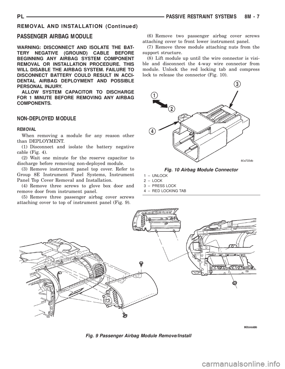
(4) Remove three screws to glove box door and
remove door from instrument panel.
(5) Remove three passenger airbag cover screws
attaching cover to top of instrument panel (Fig. 9).(6) Remove two passenger airbag cover screws
attaching cover to front lower instrument panel.
(7) Remove three module attaching nuts from the
support structure.
(8) Lift module up until the wire connector is visi-
ble and disconnect the 4-way wire connector from
module. Unlock the red locking tab and compress
lock to release the connector (Fig. 10).
Fig. 9 Passenger Airbag Module Remove/Install
Fig. 10 Airbag Module Connector
1 ± UNLOCK
2 ± LOCK
3 ± PRESS LOCK
4 ± RED LOCKING TAB
PLPASSIVE RESTRAINT SYSTEMS 8M - 7
REMOVAL AND INSTALLATION (Continued)