MPG DODGE NEON 2000 Service Repair Manual
[x] Cancel search | Manufacturer: DODGE, Model Year: 2000, Model line: NEON, Model: DODGE NEON 2000Pages: 1285, PDF Size: 29.42 MB
Page 680 of 1285

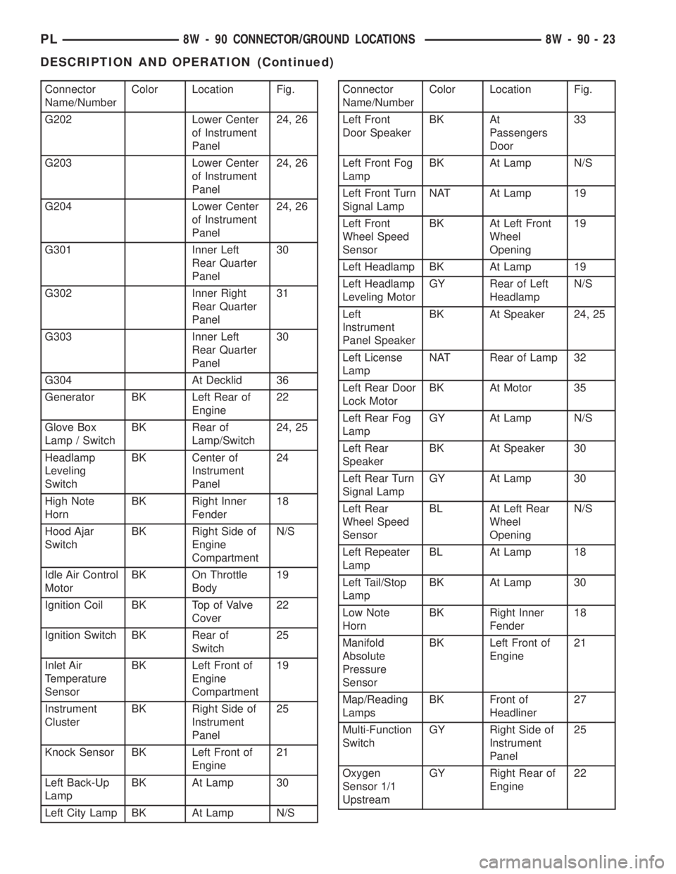
Connector
Name/NumberColor Location Fig.
G202 Lower Center
of Instrument
Panel24, 26
G203 Lower Center
of Instrument
Panel24, 26
G204 Lower Center
of Instrument
Panel24, 26
G301 Inner Left
Rear Quarter
Panel30
G302 Inner Right
Rear Quarter
Panel31
G303 Inner Left
Rear Quarter
Panel30
G304 At Decklid 36
Generator BK Left Rear of
Engine22
Glove Box
Lamp / SwitchBK Rear of
Lamp/Switch24, 25
Headlamp
Leveling
SwitchBK Center of
Instrument
Panel24
High Note
HornBK Right Inner
Fender18
Hood Ajar
SwitchBK Right Side of
Engine
CompartmentN/S
Idle Air Control
MotorBK On Throttle
Body19
Ignition Coil BK Top of Valve
Cover22
Ignition Switch BK Rear of
Switch25
Inlet Air
Temperature
SensorBK Left Front of
Engine
Compartment19
Instrument
ClusterBK Right Side of
Instrument
Panel25
Knock Sensor BK Left Front of
Engine21
Left Back-Up
LampBK At Lamp 30
Left City Lamp BK At Lamp N/SConnector
Name/NumberColor Location Fig.
Left Front
Door SpeakerBK At
Passengers
Door33
Left Front Fog
LampBK At Lamp N/S
Left Front Turn
Signal LampNAT At Lamp 19
Left Front
Wheel Speed
SensorBK At Left Front
Wheel
Opening19
Left Headlamp BK At Lamp 19
Left Headlamp
Leveling MotorGY Rear of Left
HeadlampN/S
Left
Instrument
Panel SpeakerBK At Speaker 24, 25
Left License
LampNAT Rear of Lamp 32
Left Rear Door
Lock MotorBK At Motor 35
Left Rear Fog
LampGY At Lamp N/S
Left Rear
SpeakerBK At Speaker 30
Left Rear Turn
Signal LampGY At Lamp 30
Left Rear
Wheel Speed
SensorBL At Left Rear
Wheel
OpeningN/S
Left Repeater
LampBL At Lamp 18
Left Tail/Stop
LampBK At Lamp 30
Low Note
HornBK Right Inner
Fender18
Manifold
Absolute
Pressure
SensorBK Left Front of
Engine21
Map/Reading
LampsBK Front of
Headliner27
Multi-Function
SwitchGY Right Side of
Instrument
Panel25
Oxygen
Sensor 1/1
UpstreamGY Right Rear of
Engine22
PL8W - 90 CONNECTOR/GROUND LOCATIONS 8W - 90 - 23
DESCRIPTION AND OPERATION (Continued)
Page 681 of 1285

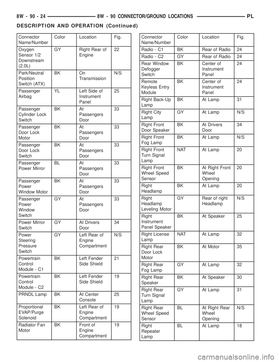
Connector
Name/NumberColor Location Fig.
Oxygen
Sensor 1/2
Downstream
(2.0L)GY Right Rear of
Engine22
Park/Neutral
Position
Switch (ATX)BK On
TransmissionN/S
Passenger
AirbagYL Left Side of
Instrument
Panel25
Passenger
Cylinder Lock
SwitchBK At
Passengers
Door33
Passenger
Door Lock
MotorBK At
Passengers
Door33
Passenger
Door Lock
SwitchBK At
Passengers
Door33
Passenger
Power MirrorBL At
Passengers
Door33
Passenger
Power
Window MotorBK At
Passengers
Door33
Passenger
Power
Window
SwitchGY At
Passengers
Door33
Power Mirror
SwitchGY At Drivers
Door34
Power
Steering
Pressure
SwitchGY Left Rear of
Engine
CompartmentN/S
Powertrain
Control
Module - C1BK Left Fender
Side Shield21
Powertrain
Control
Module - C2BK Left Fender
Side Shield19
PRNDL Lamp BK At Center
Console25
Proportional
EVAP/Purge
SolenoidBK Left Rear of
Engine
Compartment19
Radiator Fan
MotorBK Front of
Engine
Compartment19Connector
Name/NumberColor Location Fig.
Radio - C1 BK Rear of Radio 24
Radio - C2 GY Rear of Radio 24
Rear Window
Defogger
SwitchBK Center of
Instrument
Panel24
Remote
Keyless Entry
ModuleBK Center of
Instrument
Panel24
Right Back-Up
LampBK At Lamp 31
Right City
LampGY At Lamp N/S
Right Front
Door SpeakerBK At Drivers
Door34
Right Front
Fog LampBK At Lamp N/S
Right Front
Turn Signal
LampNAT At Lamp 20
Right Front
Wheel Speed
SensorBK At Right Front
Wheel
Opening20
Right
HeadlampBK At Lamp 20
Right
Headlamp
Leveling MotorGY Rear of right
HeadlampN/S
Right
Instrument
Panel SpeakerBK At Speaker 25
Right License
LampNAT At Lamp 32
Right Rear
Door Lock
MotorBK At Motor 35
Right Rear
Fog LampGY At Lamp 32
Right Rear
SpeakerBK At Speaker 30
Right Rear
Turn Signal
LampGY At Lamp 31
Right Rear
Wheel Speed
SensorBL At Right Rear
Wheel
OpeningN/S
Right
Repeater
LampBL At Lamp 18
8W - 90 - 24 8W - 90 CONNECTOR/GROUND LOCATIONSPL
DESCRIPTION AND OPERATION (Continued)