bolt pattern DODGE NEON 2000 Service Repair Manual
[x] Cancel search | Manufacturer: DODGE, Model Year: 2000, Model line: NEON, Model: DODGE NEON 2000Pages: 1285, PDF Size: 29.42 MB
Page 175 of 1285

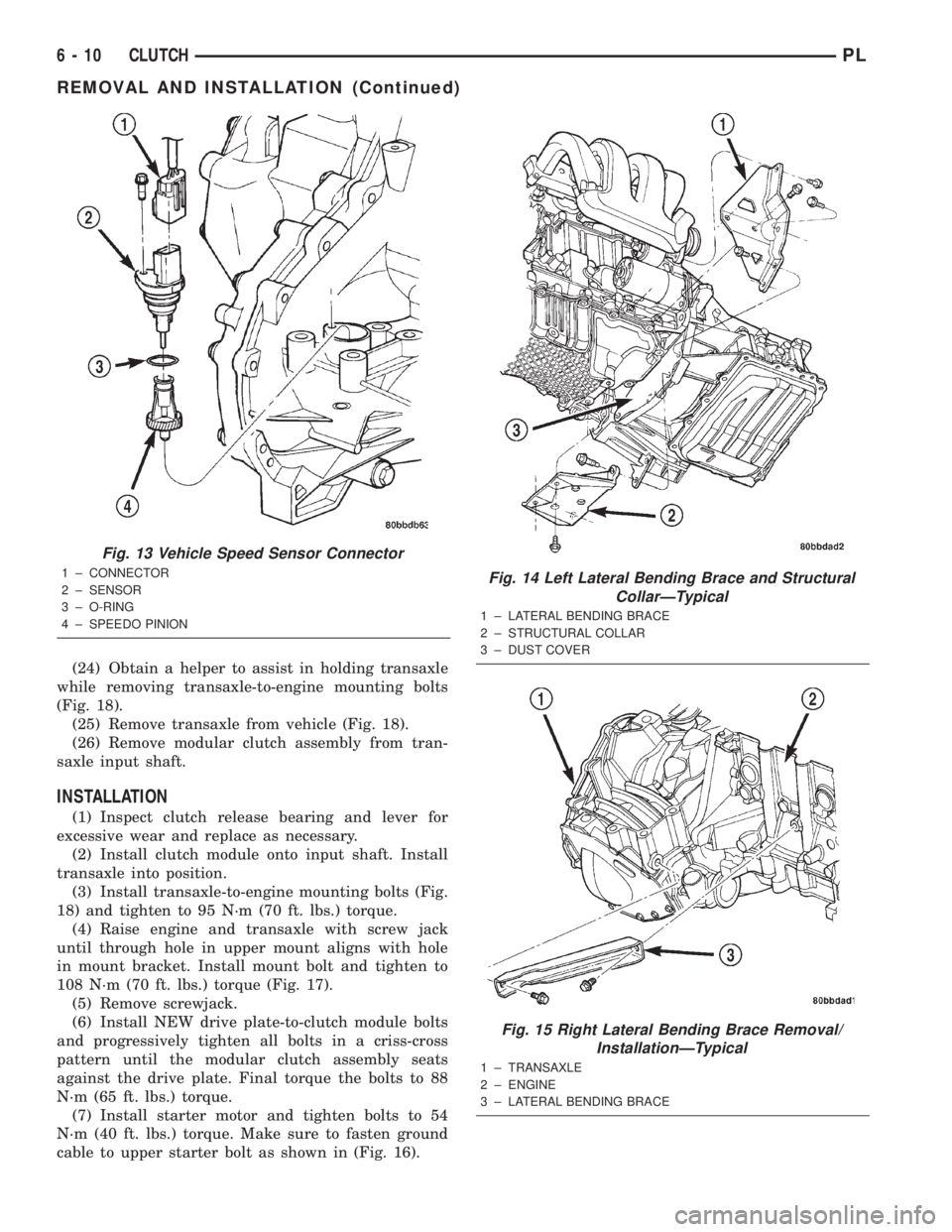
(24) Obtain a helper to assist in holding transaxle
while removing transaxle-to-engine mounting bolts
(Fig. 18).
(25) Remove transaxle from vehicle (Fig. 18).
(26) Remove modular clutch assembly from tran-
saxle input shaft.
INSTALLATION
(1) Inspect clutch release bearing and lever for
excessive wear and replace as necessary.
(2) Install clutch module onto input shaft. Install
transaxle into position.
(3) Install transaxle-to-engine mounting bolts (Fig.
18) and tighten to 95 N´m (70 ft. lbs.) torque.
(4) Raise engine and transaxle with screw jack
until through hole in upper mount aligns with hole
in mount bracket. Install mount bolt and tighten to
108 N´m (70 ft. lbs.) torque (Fig. 17).
(5) Remove screwjack.
(6) Install NEW drive plate-to-clutch module bolts
and progressively tighten all bolts in a criss-cross
pattern until the modular clutch assembly seats
against the drive plate. Final torque the bolts to 88
N´m (65 ft. lbs.) torque.
(7) Install starter motor and tighten bolts to 54
N´m (40 ft. lbs.) torque. Make sure to fasten ground
cable to upper starter bolt as shown in (Fig. 16).
Fig. 13 Vehicle Speed Sensor Connector
1 ± CONNECTOR
2 ± SENSOR
3 ± O-RING
4 ± SPEEDO PINIONFig. 14 Left Lateral Bending Brace and Structural
CollarÐTypical
1 ± LATERAL BENDING BRACE
2 ± STRUCTURAL COLLAR
3 ± DUST COVER
Fig. 15 Right Lateral Bending Brace Removal/
InstallationÐTypical
1 ± TRANSAXLE
2 ± ENGINE
3 ± LATERAL BENDING BRACE
6 - 10 CLUTCHPL
REMOVAL AND INSTALLATION (Continued)
Page 727 of 1285

will clean up a bore and maintain the required lim-
its.
(2) Deglazing of the cylinder walls may be done
using a cylinder surfacing hone, recommended tool
C-3501 or equivalent, equipped with 280 grit stones,
if the cylinder bore is straight and round. 20±60
strokes depending on the bore condition, will be suf-
ficient to provide a satisfactory surface. Inspect cyl-
inder walls after each 20 strokes, using a light
honing oil.Do not use engine or transmission oil,
mineral spirits or kerosene.
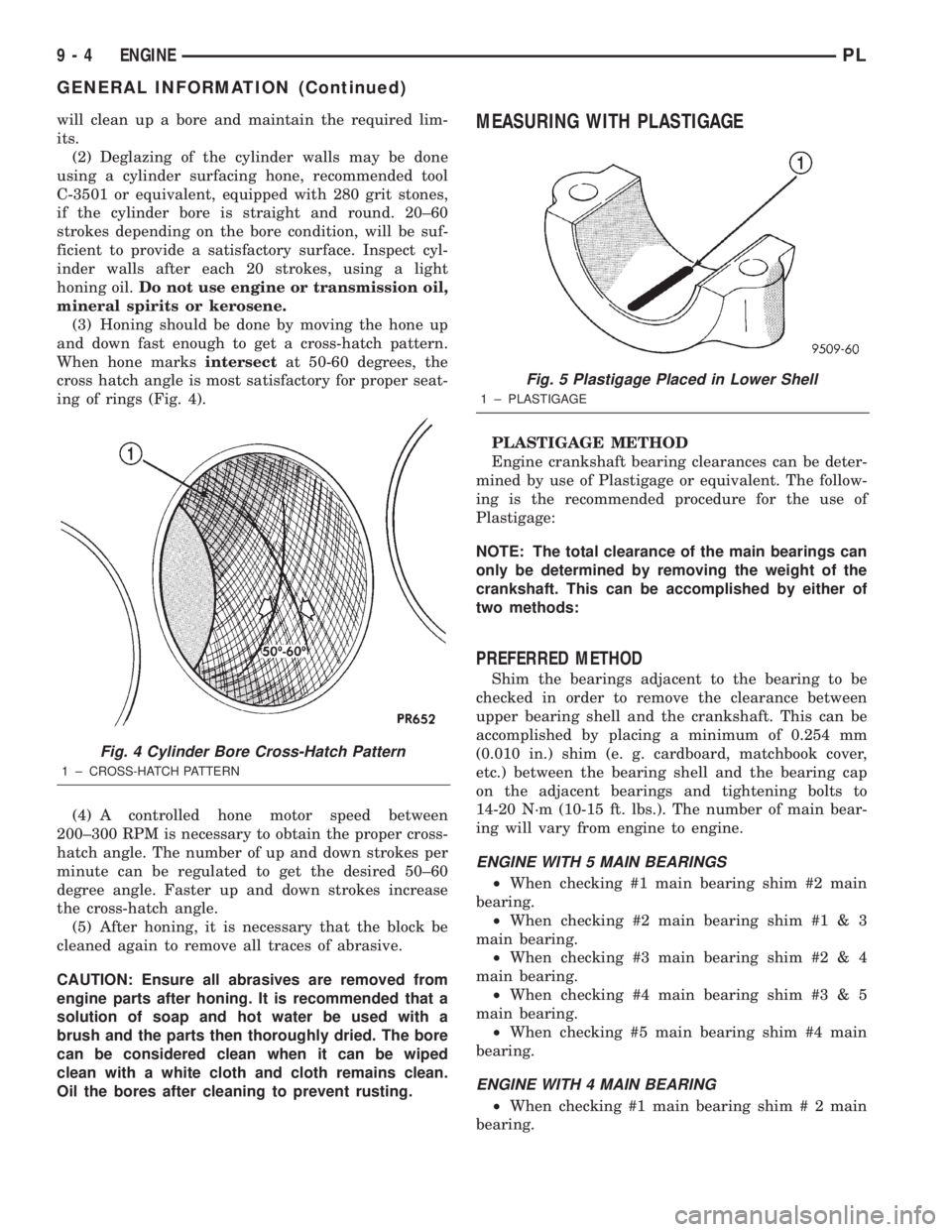
(3) Honing should be done by moving the hone up
and down fast enough to get a cross-hatch pattern.
When hone marksintersectat 50-60 degrees, the
cross hatch angle is most satisfactory for proper seat-
ing of rings (Fig. 4).
(4) A controlled hone motor speed between
200±300 RPM is necessary to obtain the proper cross-
hatch angle. The number of up and down strokes per
minute can be regulated to get the desired 50±60
degree angle. Faster up and down strokes increase
the cross-hatch angle.
(5) After honing, it is necessary that the block be
cleaned again to remove all traces of abrasive.
CAUTION: Ensure all abrasives are removed from
engine parts after honing. It is recommended that a
solution of soap and hot water be used with a
brush and the parts then thoroughly dried. The bore
can be considered clean when it can be wiped
clean with a white cloth and cloth remains clean.
Oil the bores after cleaning to prevent rusting.MEASURING WITH PLASTIGAGE
PLASTIGAGE METHOD
Engine crankshaft bearing clearances can be deter-
mined by use of Plastigage or equivalent. The follow-
ing is the recommended procedure for the use of
Plastigage:
NOTE: The total clearance of the main bearings can
only be determined by removing the weight of the
crankshaft. This can be accomplished by either of
two methods:
PREFERRED METHOD
Shim the bearings adjacent to the bearing to be
checked in order to remove the clearance between
upper bearing shell and the crankshaft. This can be
accomplished by placing a minimum of 0.254 mm
(0.010 in.) shim (e. g. cardboard, matchbook cover,
etc.) between the bearing shell and the bearing cap
on the adjacent bearings and tightening bolts to
14-20 N´m (10-15 ft. lbs.). The number of main bear-
ing will vary from engine to engine.
ENGINE WITH 5 MAIN BEARINGS
²When checking #1 main bearing shim #2 main
bearing.
²When checking #2 main bearing shim #1 & 3
main bearing.
²When checking #3 main bearing shim #2 & 4
main bearing.
²When checking #4 main bearing shim #3 & 5
main bearing.
²When checking #5 main bearing shim #4 main
bearing.
ENGINE WITH 4 MAIN BEARING
²When checking #1 main bearing shim # 2 main
bearing.
Fig. 4 Cylinder Bore Cross-Hatch Pattern
1 ± CROSS-HATCH PATTERN
Fig. 5 Plastigage Placed in Lower Shell
1 ± PLASTIGAGE
9 - 4 ENGINEPL
GENERAL INFORMATION (Continued)