flex plate DODGE NEON 2000 Service Repair Manual
[x] Cancel search | Manufacturer: DODGE, Model Year: 2000, Model line: NEON, Model: DODGE NEON 2000Pages: 1285, PDF Size: 29.42 MB
Page 121 of 1285
REMOVAL
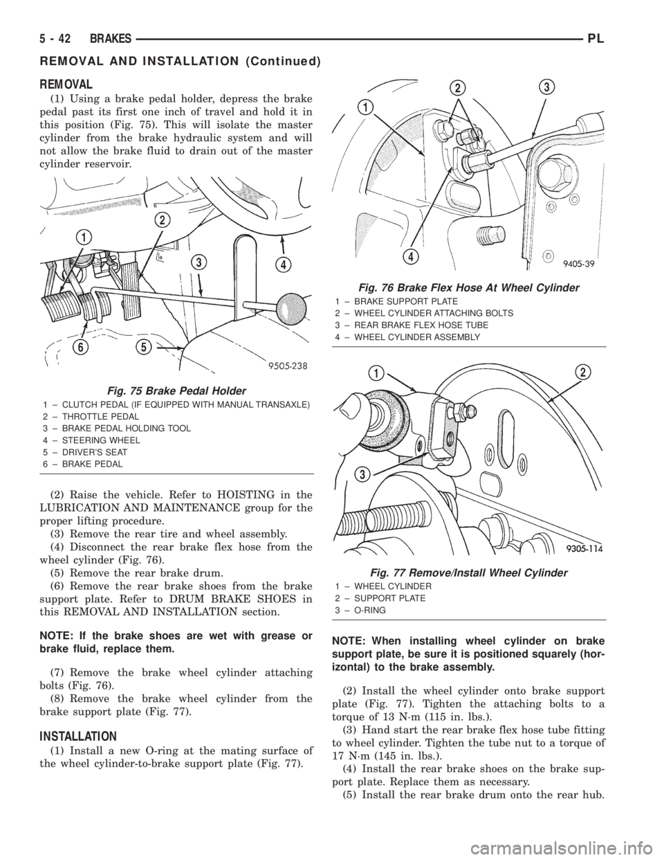
(1) Using a brake pedal holder, depress the brake
pedal past its first one inch of travel and hold it in
this position (Fig. 75). This will isolate the master
cylinder from the brake hydraulic system and will
not allow the brake fluid to drain out of the master
cylinder reservoir.
(2) Raise the vehicle. Refer to HOISTING in the
LUBRICATION AND MAINTENANCE group for the
proper lifting procedure.
(3) Remove the rear tire and wheel assembly.
(4) Disconnect the rear brake flex hose from the
wheel cylinder (Fig. 76).
(5) Remove the rear brake drum.
(6) Remove the rear brake shoes from the brake
support plate. Refer to DRUM BRAKE SHOES in
this REMOVAL AND INSTALLATION section.
NOTE: If the brake shoes are wet with grease or
brake fluid, replace them.
(7) Remove the brake wheel cylinder attaching
bolts (Fig. 76).
(8) Remove the brake wheel cylinder from the
brake support plate (Fig. 77).
INSTALLATION
(1) Install a new O-ring at the mating surface of
the wheel cylinder-to-brake support plate (Fig. 77).NOTE: When installing wheel cylinder on brake
support plate, be sure it is positioned squarely (hor-
izontal) to the brake assembly.
(2) Install the wheel cylinder onto brake support
plate (Fig. 77). Tighten the attaching bolts to a
torque of 13 N´m (115 in. lbs.).
(3) Hand start the rear brake flex hose tube fitting
to wheel cylinder. Tighten the tube nut to a torque of
17 N´m (145 in. lbs.).
(4) Install the rear brake shoes on the brake sup-
port plate. Replace them as necessary.
(5) Install the rear brake drum onto the rear hub.
Fig. 75 Brake Pedal Holder
1 ± CLUTCH PEDAL (IF EQUIPPED WITH MANUAL TRANSAXLE)
2 ± THROTTLE PEDAL
3 ± BRAKE PEDAL HOLDING TOOL
4 ± STEERING WHEEL
5 ± DRIVER'S SEAT
6 ± BRAKE PEDAL
Fig. 76 Brake Flex Hose At Wheel Cylinder
1 ± BRAKE SUPPORT PLATE
2 ± WHEEL CYLINDER ATTACHING BOLTS
3 ± REAR BRAKE FLEX HOSE TUBE
4 ± WHEEL CYLINDER ASSEMBLY
Fig. 77 Remove/Install Wheel Cylinder
1 ± WHEEL CYLINDER
2 ± SUPPORT PLATE
3 ± O-RING
5 - 42 BRAKESPL
REMOVAL AND INSTALLATION (Continued)
Page 125 of 1285
(4) Remove the brake drum (Fig. 87).
NOTE: If the drum does not come off, further brake
clearance can be obtained by backing off the brake
automatic adjuster screw. Remove the rubber plug
from the top of brake support plate. Rotate the
automatic adjuster screw in an upward motion,
using a screwdriver.
INSTALLATION
NOTE: Before installing the drum, inspect the brake
shoe linings for wear, shoe alignment, and contam-
ination.
(1) Install the rear brake drum on rear hub and
bearing (Fig. 87).
(2) Install the tire and wheel assembly. Tighten
the wheel mounting nuts to a torque of 135 N´m (100
ft. lbs.).
(3) Adjust the rear brake shoes as necessary. Refer
to ADJUSTMENTS in this section of this service
manual group.
(4) Lower the vehicle.
DRUM BRAKE SHOE SUPPORT PLATE (REAR)
NOTE: Before proceeding with this procedure,
review SERVICE WARNINGS AND CAUTIONS at the
beginning of REMOVAL AND INSTALLATION in this
section.
REMOVAL
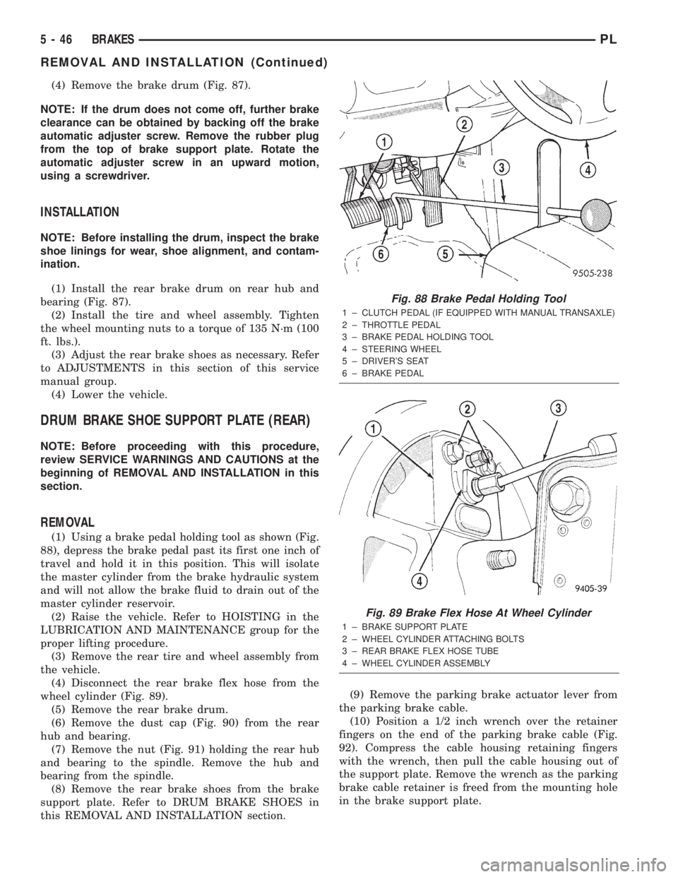
(1) Using a brake pedal holding tool as shown (Fig.
88), depress the brake pedal past its first one inch of
travel and hold it in this position. This will isolate
the master cylinder from the brake hydraulic system
and will not allow the brake fluid to drain out of the
master cylinder reservoir.
(2) Raise the vehicle. Refer to HOISTING in the
LUBRICATION AND MAINTENANCE group for the
proper lifting procedure.
(3) Remove the rear tire and wheel assembly from
the vehicle.
(4) Disconnect the rear brake flex hose from the
wheel cylinder (Fig. 89).
(5) Remove the rear brake drum.
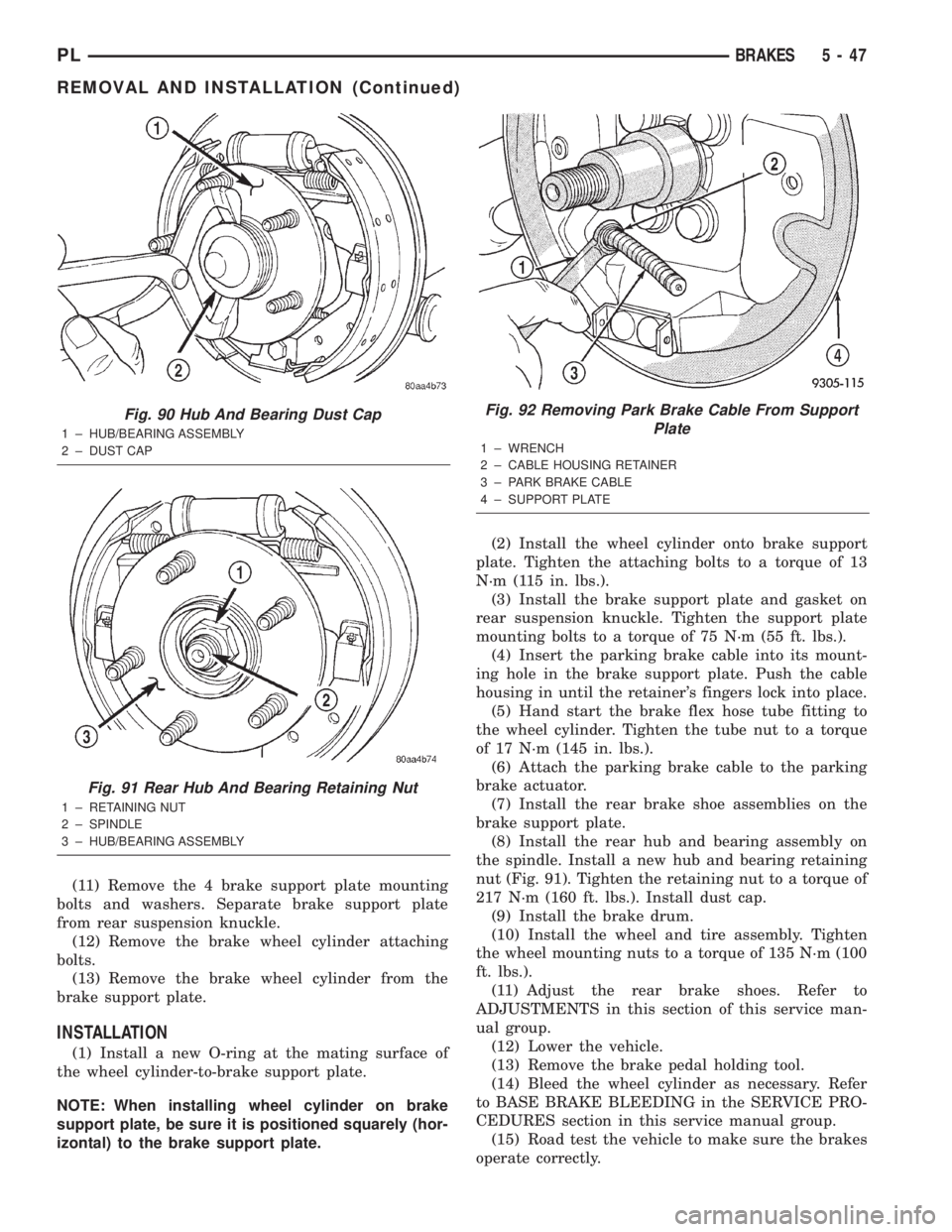
(6) Remove the dust cap (Fig. 90) from the rear
hub and bearing.
(7) Remove the nut (Fig. 91) holding the rear hub
and bearing to the spindle. Remove the hub and
bearing from the spindle.
(8) Remove the rear brake shoes from the brake
support plate. Refer to DRUM BRAKE SHOES in
this REMOVAL AND INSTALLATION section.(9) Remove the parking brake actuator lever from
the parking brake cable.
(10) Position a 1/2 inch wrench over the retainer
fingers on the end of the parking brake cable (Fig.
92). Compress the cable housing retaining fingers
with the wrench, then pull the cable housing out of
the support plate. Remove the wrench as the parking
brake cable retainer is freed from the mounting hole
in the brake support plate.
Fig. 88 Brake Pedal Holding Tool
1 ± CLUTCH PEDAL (IF EQUIPPED WITH MANUAL TRANSAXLE)
2 ± THROTTLE PEDAL
3 ± BRAKE PEDAL HOLDING TOOL
4 ± STEERING WHEEL
5 ± DRIVER'S SEAT
6 ± BRAKE PEDAL
Fig. 89 Brake Flex Hose At Wheel Cylinder
1 ± BRAKE SUPPORT PLATE
2 ± WHEEL CYLINDER ATTACHING BOLTS
3 ± REAR BRAKE FLEX HOSE TUBE
4 ± WHEEL CYLINDER ASSEMBLY
5 - 46 BRAKESPL
REMOVAL AND INSTALLATION (Continued)
Page 126 of 1285
(11) Remove the 4 brake support plate mounting
bolts and washers. Separate brake support plate
from rear suspension knuckle.
(12) Remove the brake wheel cylinder attaching
bolts.
(13) Remove the brake wheel cylinder from the
brake support plate.
INSTALLATION
(1) Install a new O-ring at the mating surface of
the wheel cylinder-to-brake support plate.
NOTE: When installing wheel cylinder on brake
support plate, be sure it is positioned squarely (hor-
izontal) to the brake support plate.(2) Install the wheel cylinder onto brake support
plate. Tighten the attaching bolts to a torque of 13
N´m (115 in. lbs.).
(3) Install the brake support plate and gasket on
rear suspension knuckle. Tighten the support plate
mounting bolts to a torque of 75 N´m (55 ft. lbs.).
(4) Insert the parking brake cable into its mount-
ing hole in the brake support plate. Push the cable
housing in until the retainer's fingers lock into place.
(5) Hand start the brake flex hose tube fitting to
the wheel cylinder. Tighten the tube nut to a torque
of 17 N´m (145 in. lbs.).
(6) Attach the parking brake cable to the parking
brake actuator.
(7) Install the rear brake shoe assemblies on the
brake support plate.
(8) Install the rear hub and bearing assembly on
the spindle. Install a new hub and bearing retaining
nut (Fig. 91). Tighten the retaining nut to a torque of
217 N´m (160 ft. lbs.). Install dust cap.
(9) Install the brake drum.
(10) Install the wheel and tire assembly. Tighten
the wheel mounting nuts to a torque of 135 N´m (100
ft. lbs.).
(11) Adjust the rear brake shoes. Refer to
ADJUSTMENTS in this section of this service man-
ual group.
(12) Lower the vehicle.
(13) Remove the brake pedal holding tool.
(14) Bleed the wheel cylinder as necessary. Refer
to BASE BRAKE BLEEDING in the SERVICE PRO-
CEDURES section in this service manual group.
(15) Road test the vehicle to make sure the brakes
operate correctly.
Fig. 90 Hub And Bearing Dust Cap
1 ± HUB/BEARING ASSEMBLY
2 ± DUST CAP
Fig. 91 Rear Hub And Bearing Retaining Nut
1 ± RETAINING NUT
2 ± SPINDLE
3 ± HUB/BEARING ASSEMBLY
Fig. 92 Removing Park Brake Cable From Support
Plate
1 ± WRENCH
2 ± CABLE HOUSING RETAINER
3 ± PARK BRAKE CABLE
4 ± SUPPORT PLATE
PLBRAKES 5 - 47
REMOVAL AND INSTALLATION (Continued)
Page 724 of 1285
ENGINE
TABLE OF CONTENTS
page page
STANDARD SERVICE PROCEDURES........... 1
ENGINE DIAGNOSIS........................ 82.0L SOHC ENGINE....................... 15
STANDARD SERVICE PROCEDURES
TABLE OF CONTENTS
page page
GENERAL INFORMATION
FORM-IN-PLACE GASKETS & SEALERS........1
ENGINE GASKET SURFACE PREPARATION.....2
CRANKSHAFT DAMPER BOLT ACCESS PLUG . . . 2
ENGINE CORE PLUGS.....................2
ENGINE PERFORMANCE...................3HONING CYLINDER BORES.................3
MEASURING WITH PLASTIGAGE.............4
REPAIR OF DAMAGED OR WORN THREADS....5
HYDROSTATIC LOCKED ENGINE.............5
CHECKING ENGINE OIL LEVEL..............6
ENGINE OIL SERVICE......................7
GENERAL INFORMATION
FORM-IN-PLACE GASKETS & SEALERS
There are numerous places where form-in-place
gaskets are used on the engine. Care must be taken
when applying form-in-place gaskets to assure
obtaining the desired results.Do not use form-in-
place gasket material unless specified.Bead size,
continuity, and location are of great importance. Too
thin a bead can result in leakage while too much can
result in spill-over which can break off and obstruct
fluid feed lines. A continuous bead of the proper
width is essential to obtain a leak-free gasket.
There are numerous types of form-in-place gasket
materials that are used in the engine area. Mopart
Engine RTV GEN II, MopartATF-RTV, and Mopart
Gasket Maker gasket materials, each have different
properties and can not be used in place of the other.
MOPARtENGINE RTV GEN II
MopartEngine RTV GEN II is used to seal com-
ponents exposed to engine oil. This material is a spe-
cially designed black silicone rubber RTV that
retains adhesion and sealing properties when
exposed to engine oil. Moisture in the air causes the
material to cure. This material is available in three
ounce tubes and has a shelf life of one year. After one
year this material will not properly cure. Alwaysinspect the package for the expiration date before
use.
MOPARtATF RTV
MopartATF RTV is a specifically designed black
silicone rubber RTV that retains adhesion and seal-
ing properties to seal components exposed to auto-
matic transmission fluid, engine coolants, and
moisture. This material is available in three ounce
tubes and has a shelf life of one year. After one year
this material will not properly cure. Always inspect
the package for the expiration date before use.
MOPARtGASKET MAKER
MopartGasket Maker is an anaerobic type gasket
material. The material cures in the absence of air
when squeezed between two metallic surfaces. It will
not cure if left in the uncovered tube. The anaerobic
material is for use between two machined surfaces.
Do not use on flexible metal flanges.
MOPARtBED PLATE SEALANT
MopartBed Plate Sealant is a unique (green-in-
color) anaerobic type gasket material that is specially
made to seal the area between the bedplate and cyl-
inder block without disturbing the bearing clearance
or alignment of these components. The material
cures slowly in the absence of air when torqued
between two metallic surfaces, and will rapidly cure
when heat is applied.
PLENGINE 9 - 1
Page 754 of 1285
(7) Connect CCV hose on cylinder head cover port.
(8) Raise vehicle.
(9) Install new flex joint to manifold flange gasket.
(10) Attach exhaust system to manifold flange and
tighten fasteners to 28 N´m (250 in. lbs.).
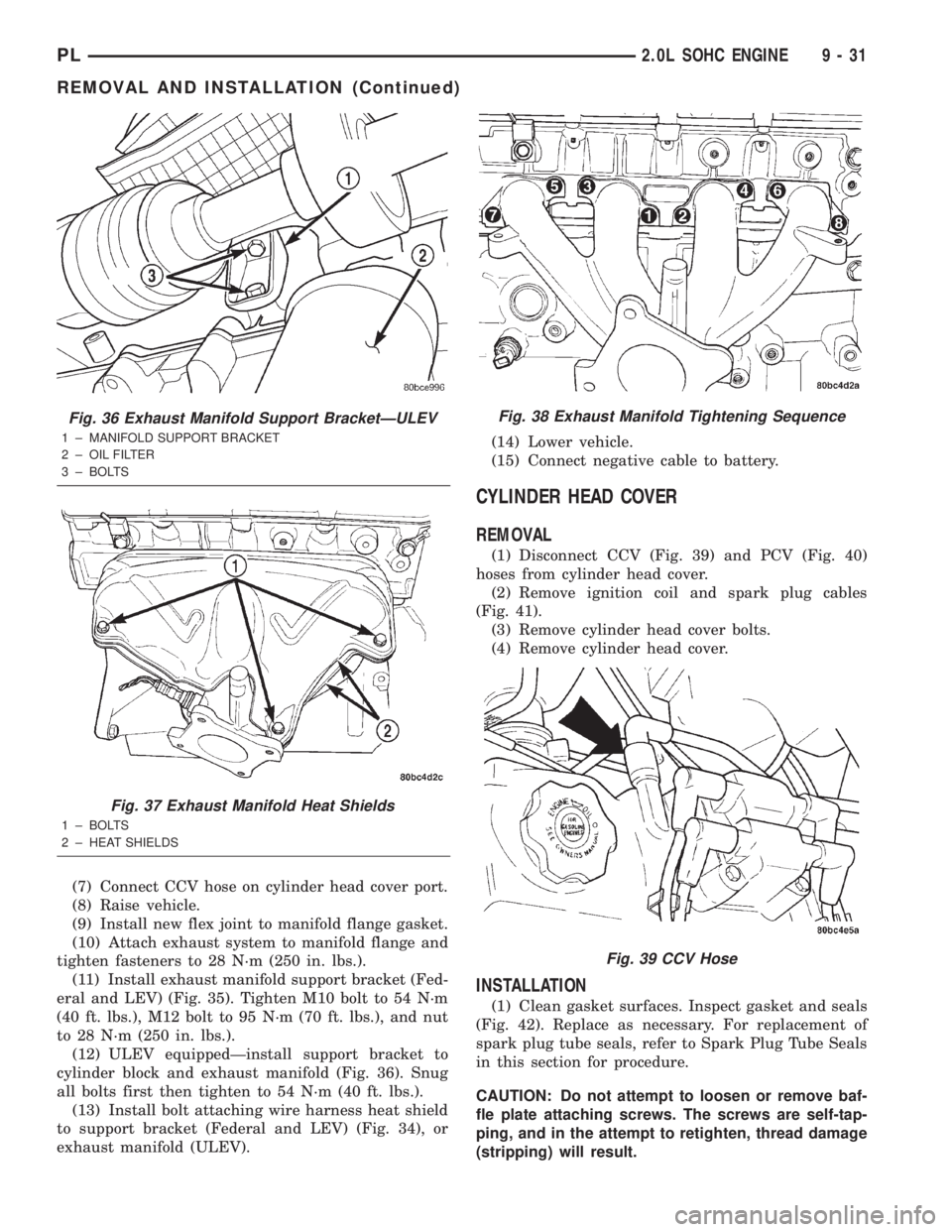
(11) Install exhaust manifold support bracket (Fed-
eral and LEV) (Fig. 35). Tighten M10 bolt to 54 N´m
(40 ft. lbs.), M12 bolt to 95 N´m (70 ft. lbs.), and nut
to 28 N´m (250 in. lbs.).
(12) ULEV equippedÐinstall support bracket to
cylinder block and exhaust manifold (Fig. 36). Snug
all bolts first then tighten to 54 N´m (40 ft. lbs.).
(13) Install bolt attaching wire harness heat shield
to support bracket (Federal and LEV) (Fig. 34), or
exhaust manifold (ULEV).(14) Lower vehicle.
(15) Connect negative cable to battery.
CYLINDER HEAD COVER
REMOVAL
(1) Disconnect CCV (Fig. 39) and PCV (Fig. 40)
hoses from cylinder head cover.
(2) Remove ignition coil and spark plug cables
(Fig. 41).
(3) Remove cylinder head cover bolts.
(4) Remove cylinder head cover.
INSTALLATION
(1) Clean gasket surfaces. Inspect gasket and seals
(Fig. 42). Replace as necessary. For replacement of
spark plug tube seals, refer to Spark Plug Tube Seals
in this section for procedure.
CAUTION: Do not attempt to loosen or remove baf-
fle plate attaching screws. The screws are self-tap-
ping, and in the attempt to retighten, thread damage
(stripping) will result.
Fig. 36 Exhaust Manifold Support BracketÐULEV
1 ± MANIFOLD SUPPORT BRACKET
2 ± OIL FILTER
3 ± BOLTS
Fig. 37 Exhaust Manifold Heat Shields
1 ± BOLTS
2 ± HEAT SHIELDS
Fig. 38 Exhaust Manifold Tightening Sequence
Fig. 39 CCV Hose
PL2.0L SOHC ENGINE 9 - 31
REMOVAL AND INSTALLATION (Continued)
Page 968 of 1285
GENERAL INFORMATION
IN VEHICLE SERVICE
The following components are serviceable in the
vehicle without transaxle removal:
²Valve Body Assembly
²Converter Clutch Solenoid
²Governor
²Vehicle Speed Sensor & Pinion
²Park/Neutral & Back-up Lamp Switch
²Transfer Gears and Transfer Shaft
²Low/Reverse Servo
²Kickdown Servo
²Accumulator
FLUID REQUIREMENTS
NOTE: The transmission and differential have a
common oil sump with an opening between the
two.
TRANSMISSION/DIFFERENTIAL
MopartATF+4 (Automatic Transmission Fluid
Type 9602) is required in this transaxle. Substitute
fluids must meet fluid specification MS-9602.
FLUID ADDITIVES
Chrysler Corporation strongly recommends against
the addition of any fluids to the transmission, other
than those automatic transmission fluids listed
above. Exceptions to this policy are the use of special
dyes to aid in detecting fluid leaks.
Various ªspecialº additives and supplements exist
that claim to improve shift feel/quality and converter
clutch operation, inhibit overheating, oxidation, var-
nish and sludge. These claims have not been sup-
ported to Chrysler's satisfaction and these additives
must not be used. The use of transmission ªsealersº
should also be avoided, since they may adversely
affect the integrity of tranmission seals.
DESCRIPTION AND OPERATION
31TH GENERAL INFORMATION
NOTE: Safety goggles should be worn at all times
when working on these transaxles.
This transaxle combines torque converter, three
speed transmission, final drive gearing, and differen-
tial into a front wheel drive system.
NOTE: Transaxle operation requirements are differ-
ent for each vehicle and engine combination. Some
internal parts will be different to provide for this.Therefore, when replacing parts, refer to the seven
digit part number stamped on rear of the transaxle
oil pan flange.
Within this transaxle, there are three primary
areas:
(1) Main center line plus valve body.
(2) Transfer shaft center line (includes governor
and parking sprag).
(3) Differential center line.
Center distances between the main rotating parts
in these three areas are held precise to maintain a
low noise level.
The torque converter, transaxle area, and differen-
tial are housed in an integral aluminum die casting.
The differential oil sump is common with the
transaxle sump. Separate filling of the differen-
tial is NOT necessary.
The torque converter is attached to the crankshaft
through a flexible driving plate. Cooling of the con-
verter is accomplished by circulating the transaxle
fluid through a remote cooler. There are two types of
coolers used. An oil-to-water type cooler located in
the radiator side tank and/or an oil-to-air heat
exchanger. The torque converter assembly is a sealed
unit that cannot be disassembled.
The transaxle fluid is filtered by an internal filter
attached to the lower side of the valve body assembly.
Engine torque is transmitted to the torque con-
verter and then through the input shaft to multiple-
disc clutches in the transaxle. The power flow
depends on the application of the clutches and bands.
Refer to Elements in Use Chart in Diagnosis and
Tests section.
The transaxle consists of:
²Two multiple-disc clutches
²An overrunning clutch
²Two servos
²A hydraulic accumulator
²Two bands
²Two planetary gear sets
This provides three forward ratios and a reverse
ratio. The common sun gear of the planetary gear
sets is connected to the front clutch by a driving
shell. The driving shell is splined to the sun gear and
front clutch retainer. The hydraulic system consists
of an oil pump and a single valve body which con-
tains all of the valves except the governor valves.
The transaxle sump and differential sump are both
vented through the dipstick. Output torque from the
main center line is delivered through helical gears to
the transfer shaft. This gear set is a factor in the
transaxle final drive (axle) ratio. The shaft also car-
ries the governor and parking sprag. An integral heli-
cal gear on the transfer shaft drives the differential
ring gear.
PLTRANSAXLE 21 - 55