width DODGE NEON 2000 Service Repair Manual
[x] Cancel search | Manufacturer: DODGE, Model Year: 2000, Model line: NEON, Model: DODGE NEON 2000Pages: 1285, PDF Size: 29.42 MB
Page 12 of 1285
SUSPENSION
TABLE OF CONTENTS
page page
WHEEL ALIGNMENT........................ 1
FRONT SUSPENSION....................... 9REAR SUSPENSION....................... 35
WHEEL ALIGNMENT
TABLE OF CONTENTS
page page
DESCRIPTION AND OPERATION
WHEEL ALIGNMENT.......................1
DIAGNOSIS AND TESTING
SUSPENSION AND STEERING DIAGNOSIS.....3
SERVICE PROCEDURES
CURB HEIGHT MEASUREMENT..............5WHEEL ALIGNMENT.......................5
SPECIFICATIONS
WHEEL ALIGNMENT SPECIFICATIONS.........8
DESCRIPTION AND OPERATION
WHEEL ALIGNMENT
Proper vehicle wheel alignment is the proper
adjustment of all interrelated front and rear suspen-
sion angles. These angles are what affects the han-
dling and steering of the vehicle when it is in motion.
The method of checking a vehicle's front and rear
wheel alignment will vary depending on the type and
manufacturer of the equipment being used. Instruc-
tions furnished by the manufacturer of the equip-
ment being used should always be followed to ensure
accuracy of the alignment, except when alignment
specifications recommended by this corporation differ.
Typical wheel alignment angles and measurements
are camber, caster, toe, and thrust angle.
²Camber is the number of degrees the top of the
tire and wheel are tilted either inward or outward
(Fig. 1). Camber is a tire wearing angle. Excessive
negative camber will cause tread wear at the inside
of the tire, while excessive positive camber will cause
outside tire wear.²Caster is the number of degrees of forward or
rearward tilt of the steering knuckle. Forward tilt
provides a negative caster angle, while rearward tilt
provides a positive caster angle. Caster is not adjust-
able on this vehicle.
²Cross Camber is the difference between left and
right camber. The right side camber is to be sub-
tracted from the left, resulting in the cross camber
reading. For example, if the left camber is +0.3É and
the right camber is 0.0É, the cross camber would be
+0.3É.
²Toe is measured in degrees or inches and is the
difference in width between the centered leading and
trailing edges of the tires on the same axle (Fig. 1).
Toe-in means that the front width is more narrow
than the rear. Toe-out means that the front width is
wider than the rear.
²Thrust Angle is defined as the average of the toe
settings on each rear wheel. If this measurement is
out of specification, readjust the rear wheel toe so
that each wheel has 1/2 of the total toe measure-
ment. When readjusting, do not exceed the total toe
specification.
PLSUSPENSION 2 - 1
Page 139 of 1285
If the brake shoe assemblies do not require
replacement, reinstall the assemblies making sure
each brake shoe is returned to the original position.
Refer to DISC BRAKE SHOES in the REMOVAL
AND INSTALLATION section in this section of this
service manual group.
CALIPER INSPECTION
Check for brake fluid leaks in and around the boot
area. Check for any ruptures, brittleness or damage
to the piston dust boot. If the boot is damaged, or a
fluid leak is visible, disassemble the caliper assembly
and install a new seal and boot, and a piston if it is
scored. Refer to DISC BRAKE CALIPER in the DIS-
ASSEMBLY AND ASSEMBLY section in this section
of this service manual group.
Check the guide pin dust boots to determine if they
are in good condition. Replace if they are damaged,
dry, or found to be brittle. Refer to DISC BRAKE
CALIPER in the DISASSEMBLY AND ASSEMBLY
section in this section of this service manual group.
DISC BRAKES (REAR)
BRAKE SHOES
Clean the rear brake shoes and calipers with a
water-dampened cloth or with a brake cleaner. Do
not use a petroleum based product.
If a visual inspection does not adequately deter-
mine the condition of the lining, a physical check will
be necessary.
Remove the rear disc brake shoes. Refer to DISC
BRAKE SHOES in the REMOVAL AND INSTALLA-
TION section in this section of this service manual
group.
The combined brake shoe and lining material
thickness should be measured at the thinnest part of
the assembly.
When a set of brake shoes are worn to a total
thickness of approximately 7.0 mm (9/32 inch) or
less, they should be replaced.
Replace both brake shoe assemblies (inboard and
outboard). It is necessary that both front wheel sets
be replaced whenever brake shoe assemblies on
either side are replaced.
If the brake shoe assemblies do not require
replacement, reinstall the assemblies making sure
each brake shoe is returned to the original position.
Refer to DISC BRAKE SHOES in the REMOVAL
AND INSTALLATION section in this section of this
service manual group.
CALIPER INSPECTION
Check for brake fluid leaks in and around the boot
area. Check for any ruptures, brittleness or damage
to the piston dust boot. If the boot is damaged, or afluid leak is visible, disassemble the caliper assembly
and install a new seal and boot, and a piston if it is
scored. Refer to DISC BRAKE CALIPER in the DIS-
ASSEMBLY AND ASSEMBLY section in this section
of this service manual group.
Check the guide pin dust boots to determine if they
are in good condition. Replace if they are damaged,
dry, or found to be brittle. Refer to DISC BRAKE
CALIPER in the DISASSEMBLY AND ASSEMBLY
section in this section of this service manual group.
DRUM BRAKES (REAR)
BRAKE SHOES
Clean the rear brake shoes and springs with a
water-dampened cloth or with a brake cleaner. Do
not use a petroleum based product.
Rear brake shoe lining should show contact across
the entire width of the lining and also from the heel
to the toe of the lining. Replace the shoes if noted
otherwise.
Brake shoes with lack of contact at the toe or heel
of the brake shoe lining may be improperly ground.
Clean and inspect the brake support plate and
shoe adjuster screw. Apply a thin coat of Mopart
Multi-Purpose Lubricant or equivalent to the threads
of the self-adjuster (Fig. 124). Replace the adjuster
screw if it is corroded.
NOTE: Adjuster screws are different side-to-side.
Left side adjuster screws have left-hand threads
and right side adjuster screws have right-handed
threads.
If the old brake shoe return or hold down springs
have overheated or are damaged, replace them. Over-
heating indications are paint discoloration or dis-
torted end coils.
Fig. 124 Adjuster Screw And Lever (Typical)
1 ± OUTBOARD FORWARD
2 ± SELF ADJUSTER
3 ± OUTBOARD REAR
4 ± SELF ADJUSTER LEVER
5 - 60 BRAKESPL
CLEANING AND INSPECTION (Continued)
Page 239 of 1285
The PCM sends approximately 8 volts to the Hall-
effect sensor. This voltage is required to operate the
Hall-effect chip and the electronics inside the sensor.
A ground for the sensor is provided through the sen-
sor return circuit. The input to the PCM occurs on a
5 volt output reference circuit.
The notches generate pulses from high to low in
the crankshaft position sensor output voltage. When
a metal portion of the counterweight aligns with the
crankshaft position sensor, the sensor output voltage
goes low (less than 0.5 volts). When a notch aligns
with the sensor, voltage goes high (5.0 volts). As a
group of notches pass under the sensor, the output
voltage switches from low (metal) to high (notch)
then back to low.
If available, an oscilloscope can display the square
wave patterns of each voltage pulses. From the width
of the output voltage pulses, the PCM calculates
engine speed. The width of the pulses represent the
amount of time the output voltage stays high before
switching back to low. The period of time the sensor
output voltage stays high before switching back to
low is referred to as pulse width. The faster the
engine is operating, the smaller the pulse width on
the oscilloscope.
By counting the pulses and referencing the pulse
from the 60 degree signature notch, the PCM calcu-
lates crankshaft angle (position). In each group of
timing reference notches, the first notch represents
69 degrees before top dead center (BTDC). The sec-
ond notch represents 49 degrees BTDC. The third
notch represents 29 degrees. The last notch in each
set represents 9 degrees before top dead center
(TDC).
The timing reference notches are machined at 20É
increments. From the voltage pulse width the PCM
tells the difference between the timing reference
notches and the 60 degree signature notch. The 60
degree signature notch produces a longer pulse width
than the smaller timing reference notches. If the
camshaft position sensor input switches from high to
low when the 60 degree signature notch passes under
the crankshaft position sensor, the PCM knows cylin-
der number one is the next cylinder at TDC.CAMSHAFT POSITION SENSORÐPCM INPUT
DESCRIPTION
The camshaft position sensor attaches to the rear
of the cylinder head. The PCM determines fuel injec-
tion synchronization and cylinder identification from
inputs provided by the camshaft position sensor (Fig.
6) and crankshaft position sensor. From the two
inputs, the PCM determines crankshaft position.
OPERATION
The PCM sends approximately 8 volts to the hall
affect sensor. This voltage is required to operate the
hall effect chip and the electronics inside the sensor.
A ground for the sensor is provided through the sen-
sor return circuit. The input to the PCM occurs on a
5 volt output reference circuit.
A target magnet attaches to the rear of the cam-
shaft and indexes to the correct position. The target
magnet has four different poles arranged in an asym-
metrical pattern (Fig. 7). As the target magnet
rotates, the camshaft position sensor senses the
change in polarity (Fig. 8). The sensor output switch
switches from high (5.0 volts) to low (0.5 volts) as the
target magnet rotates. When the north pole of the
target magnet passes under the sensor, the output
switches high. The sensor output switches low when
the south pole of the target magnet passes under-
neath.
The sensor also acts as a thrust plate to control
camshaft endplay.
Fig. 6 Camshaft Position SensorÐSOHC
8D - 4 IGNITION SYSTEMPL
DESCRIPTION AND OPERATION (Continued)
Page 724 of 1285
ENGINE
TABLE OF CONTENTS
page page
STANDARD SERVICE PROCEDURES........... 1
ENGINE DIAGNOSIS........................ 82.0L SOHC ENGINE....................... 15
STANDARD SERVICE PROCEDURES
TABLE OF CONTENTS
page page
GENERAL INFORMATION
FORM-IN-PLACE GASKETS & SEALERS........1
ENGINE GASKET SURFACE PREPARATION.....2
CRANKSHAFT DAMPER BOLT ACCESS PLUG . . . 2
ENGINE CORE PLUGS.....................2
ENGINE PERFORMANCE...................3HONING CYLINDER BORES.................3
MEASURING WITH PLASTIGAGE.............4
REPAIR OF DAMAGED OR WORN THREADS....5
HYDROSTATIC LOCKED ENGINE.............5
CHECKING ENGINE OIL LEVEL..............6
ENGINE OIL SERVICE......................7
GENERAL INFORMATION
FORM-IN-PLACE GASKETS & SEALERS
There are numerous places where form-in-place
gaskets are used on the engine. Care must be taken
when applying form-in-place gaskets to assure
obtaining the desired results.Do not use form-in-
place gasket material unless specified.Bead size,
continuity, and location are of great importance. Too
thin a bead can result in leakage while too much can
result in spill-over which can break off and obstruct
fluid feed lines. A continuous bead of the proper
width is essential to obtain a leak-free gasket.
There are numerous types of form-in-place gasket
materials that are used in the engine area. Mopart
Engine RTV GEN II, MopartATF-RTV, and Mopart
Gasket Maker gasket materials, each have different
properties and can not be used in place of the other.
MOPARtENGINE RTV GEN II
MopartEngine RTV GEN II is used to seal com-
ponents exposed to engine oil. This material is a spe-
cially designed black silicone rubber RTV that
retains adhesion and sealing properties when
exposed to engine oil. Moisture in the air causes the
material to cure. This material is available in three
ounce tubes and has a shelf life of one year. After one
year this material will not properly cure. Alwaysinspect the package for the expiration date before
use.
MOPARtATF RTV
MopartATF RTV is a specifically designed black
silicone rubber RTV that retains adhesion and seal-
ing properties to seal components exposed to auto-
matic transmission fluid, engine coolants, and
moisture. This material is available in three ounce
tubes and has a shelf life of one year. After one year
this material will not properly cure. Always inspect
the package for the expiration date before use.
MOPARtGASKET MAKER
MopartGasket Maker is an anaerobic type gasket
material. The material cures in the absence of air
when squeezed between two metallic surfaces. It will
not cure if left in the uncovered tube. The anaerobic
material is for use between two machined surfaces.
Do not use on flexible metal flanges.
MOPARtBED PLATE SEALANT
MopartBed Plate Sealant is a unique (green-in-
color) anaerobic type gasket material that is specially
made to seal the area between the bedplate and cyl-
inder block without disturbing the bearing clearance
or alignment of these components. The material
cures slowly in the absence of air when torqued
between two metallic surfaces, and will rapidly cure
when heat is applied.
PLENGINE 9 - 1
Page 728 of 1285
²When checking #2 main bearing shim #1 & #3
main bearing.
²When checking #3 main bearing shim #2 & #4
main bearing.
²When checking #4 main bearing shim #3 main
bearing.
NOTE: REMOVE ALL SHIMS BEFORE REASSEM-
BLING ENGINE
ALTERNATIVE METHOD
The weight of the crankshaft can be supported by a
jack under the counterweight adjacent to the bearing
being checked.
PLASTIGAGE PROCEDURE
(1) Remove oil film from surface to be checked.
Plastigage is soluble in oil.
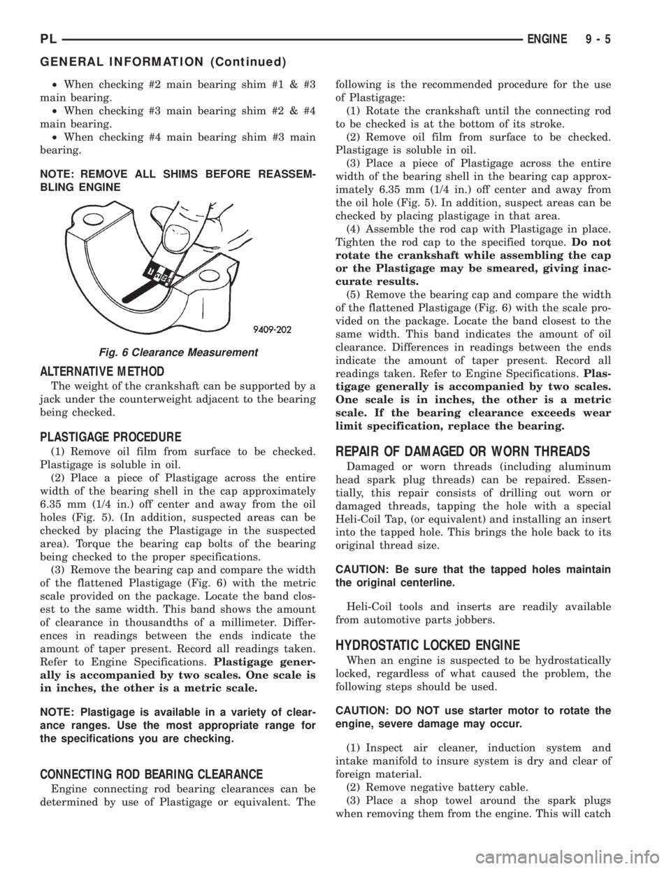
(2) Place a piece of Plastigage across the entire
width of the bearing shell in the cap approximately
6.35 mm (1/4 in.) off center and away from the oil
holes (Fig. 5). (In addition, suspected areas can be
checked by placing the Plastigage in the suspected
area). Torque the bearing cap bolts of the bearing
being checked to the proper specifications.
(3) Remove the bearing cap and compare the width
of the flattened Plastigage (Fig. 6) with the metric
scale provided on the package. Locate the band clos-
est to the same width. This band shows the amount
of clearance in thousandths of a millimeter. Differ-
ences in readings between the ends indicate the
amount of taper present. Record all readings taken.
Refer to Engine Specifications.Plastigage gener-
ally is accompanied by two scales. One scale is
in inches, the other is a metric scale.
NOTE: Plastigage is available in a variety of clear-
ance ranges. Use the most appropriate range for
the specifications you are checking.
CONNECTING ROD BEARING CLEARANCE
Engine connecting rod bearing clearances can be
determined by use of Plastigage or equivalent. Thefollowing is the recommended procedure for the use
of Plastigage:
(1) Rotate the crankshaft until the connecting rod
to be checked is at the bottom of its stroke.
(2) Remove oil film from surface to be checked.
Plastigage is soluble in oil.
(3) Place a piece of Plastigage across the entire
width of the bearing shell in the bearing cap approx-
imately 6.35 mm (1/4 in.) off center and away from
the oil hole (Fig. 5). In addition, suspect areas can be
checked by placing plastigage in that area.
(4) Assemble the rod cap with Plastigage in place.
Tighten the rod cap to the specified torque.Do not
rotate the crankshaft while assembling the cap
or the Plastigage may be smeared, giving inac-
curate results.
(5) Remove the bearing cap and compare the width
of the flattened Plastigage (Fig. 6) with the scale pro-
vided on the package. Locate the band closest to the
same width. This band indicates the amount of oil
clearance. Differences in readings between the ends
indicate the amount of taper present. Record all
readings taken. Refer to Engine Specifications.Plas-
tigage generally is accompanied by two scales.
One scale is in inches, the other is a metric
scale. If the bearing clearance exceeds wear
limit specification, replace the bearing.
REPAIR OF DAMAGED OR WORN THREADS
Damaged or worn threads (including aluminum
head spark plug threads) can be repaired. Essen-
tially, this repair consists of drilling out worn or
damaged threads, tapping the hole with a special
Heli-Coil Tap, (or equivalent) and installing an insert
into the tapped hole. This brings the hole back to its
original thread size.
CAUTION: Be sure that the tapped holes maintain
the original centerline.
Heli-Coil tools and inserts are readily available
from automotive parts jobbers.
HYDROSTATIC LOCKED ENGINE
When an engine is suspected to be hydrostatically
locked, regardless of what caused the problem, the
following steps should be used.
CAUTION: DO NOT use starter motor to rotate the
engine, severe damage may occur.
(1) Inspect air cleaner, induction system and
intake manifold to insure system is dry and clear of
foreign material.
(2) Remove negative battery cable.
(3) Place a shop towel around the spark plugs
when removing them from the engine. This will catch
Fig. 6 Clearance Measurement
PLENGINE 9 - 5
GENERAL INFORMATION (Continued)
Page 737 of 1285
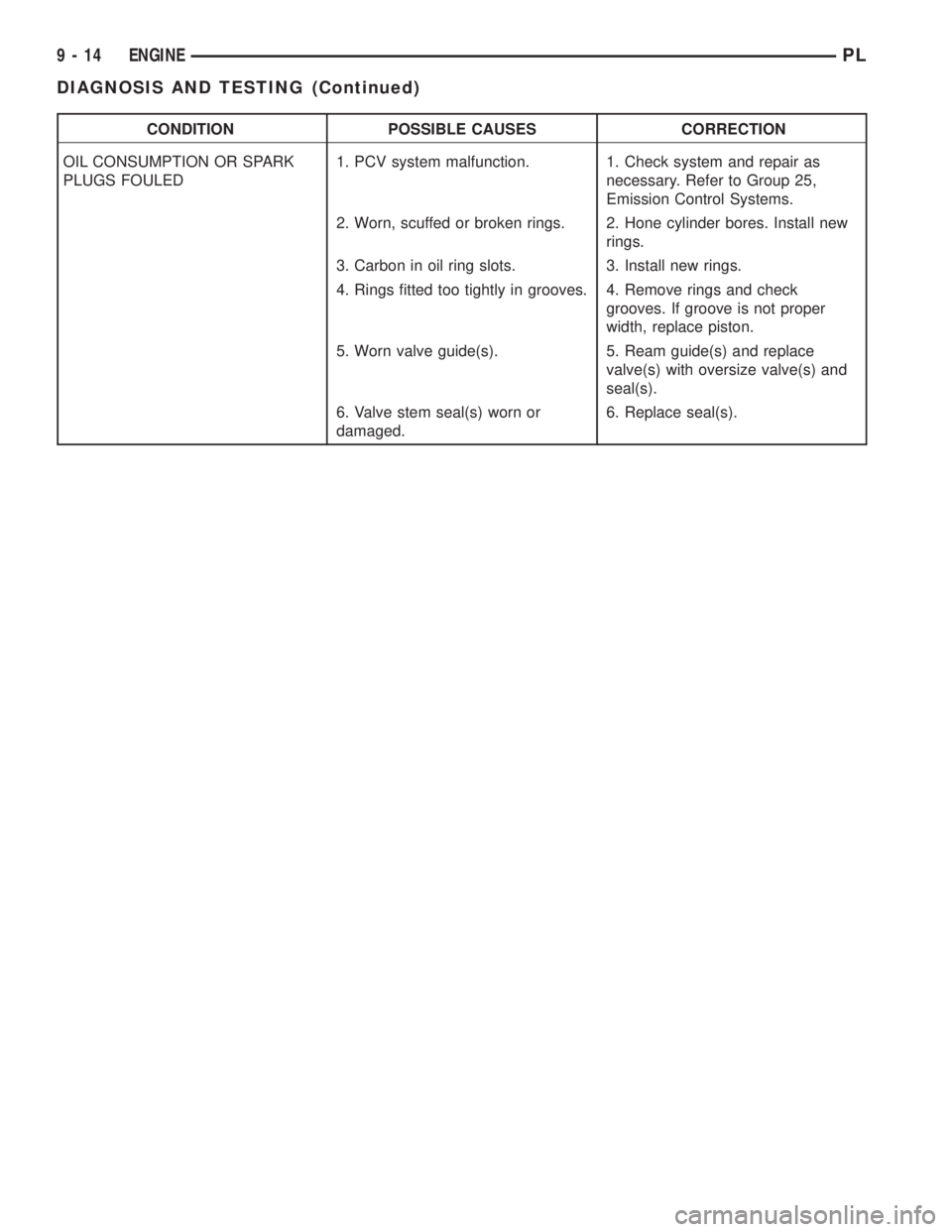
CONDITION POSSIBLE CAUSES CORRECTION
OIL CONSUMPTION OR SPARK
PLUGS FOULED1. PCV system malfunction. 1. Check system and repair as
necessary. Refer to Group 25,
Emission Control Systems.
2. Worn, scuffed or broken rings. 2. Hone cylinder bores. Install new
rings.
3. Carbon in oil ring slots. 3. Install new rings.
4. Rings fitted too tightly in grooves. 4. Remove rings and check
grooves. If groove is not proper
width, replace piston.
5. Worn valve guide(s). 5. Ream guide(s) and replace
valve(s) with oversize valve(s) and
seal(s).
6. Valve stem seal(s) worn or
damaged.6. Replace seal(s).
9 - 14 ENGINEPL
DIAGNOSIS AND TESTING (Continued)
Page 785 of 1285
then set valve in place. Rotate the valve with light
pressure. If the blue is transferred to the center of
valve face, contact is satisfactory. If the blue is trans-
ferred to top edge of the valve face, lower valve seat
with a 15 degrees stone. If the blue is transferred to
the bottom edge of valve face raise valve seat with a
65 degrees stone.
(6) Valve seats which are worn or burned can be
reworked, provided that correct angle and seat width
are maintained. The intake valve seat must be ser-
viced when the valve seat width is 2.0 mm (0.079 in.)
or greater. The exhaust valve seat must be serviced
when the valve seat width is 2.5 mm (0.098 in.) or
greater. Otherwise the cylinder head must be
replaced.
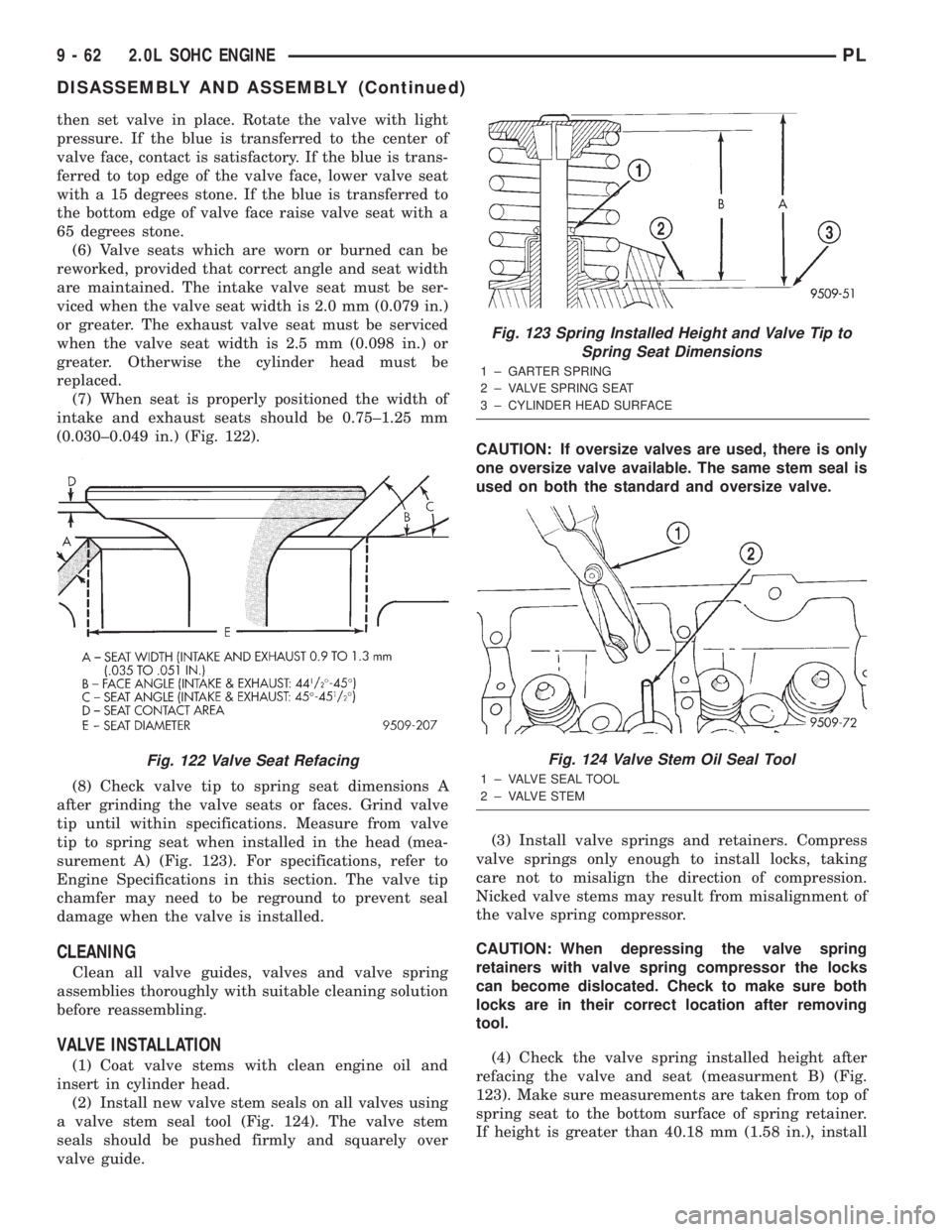
(7) When seat is properly positioned the width of
intake and exhaust seats should be 0.75±1.25 mm
(0.030±0.049 in.) (Fig. 122).
(8) Check valve tip to spring seat dimensions A
after grinding the valve seats or faces. Grind valve
tip until within specifications. Measure from valve
tip to spring seat when installed in the head (mea-
surement A) (Fig. 123). For specifications, refer to
Engine Specifications in this section. The valve tip
chamfer may need to be reground to prevent seal
damage when the valve is installed.
CLEANING
Clean all valve guides, valves and valve spring
assemblies thoroughly with suitable cleaning solution
before reassembling.
VALVE INSTALLATION
(1) Coat valve stems with clean engine oil and
insert in cylinder head.
(2) Install new valve stem seals on all valves using
a valve stem seal tool (Fig. 124). The valve stem
seals should be pushed firmly and squarely over
valve guide.CAUTION: If oversize valves are used, there is only
one oversize valve available. The same stem seal is
used on both the standard and oversize valve.
(3) Install valve springs and retainers. Compress
valve springs only enough to install locks, taking
care not to misalign the direction of compression.
Nicked valve stems may result from misalignment of
the valve spring compressor.
CAUTION: When depressing the valve spring
retainers with valve spring compressor the locks
can become dislocated. Check to make sure both
locks are in their correct location after removing
tool.
(4) Check the valve spring installed height after
refacing the valve and seat (measurment B) (Fig.
123). Make sure measurements are taken from top of
spring seat to the bottom surface of spring retainer.
If height is greater than 40.18 mm (1.58 in.), install
Fig. 122 Valve Seat Refacing
Fig. 123 Spring Installed Height and Valve Tip to
Spring Seat Dimensions
1 ± GARTER SPRING
2 ± VALVE SPRING SEAT
3 ± CYLINDER HEAD SURFACE
Fig. 124 Valve Stem Oil Seal Tool
1 ± VALVE SEAL TOOL
2 ± VALVE STEM
9 - 62 2.0L SOHC ENGINEPL
DISASSEMBLY AND ASSEMBLY (Continued)
Page 792 of 1285
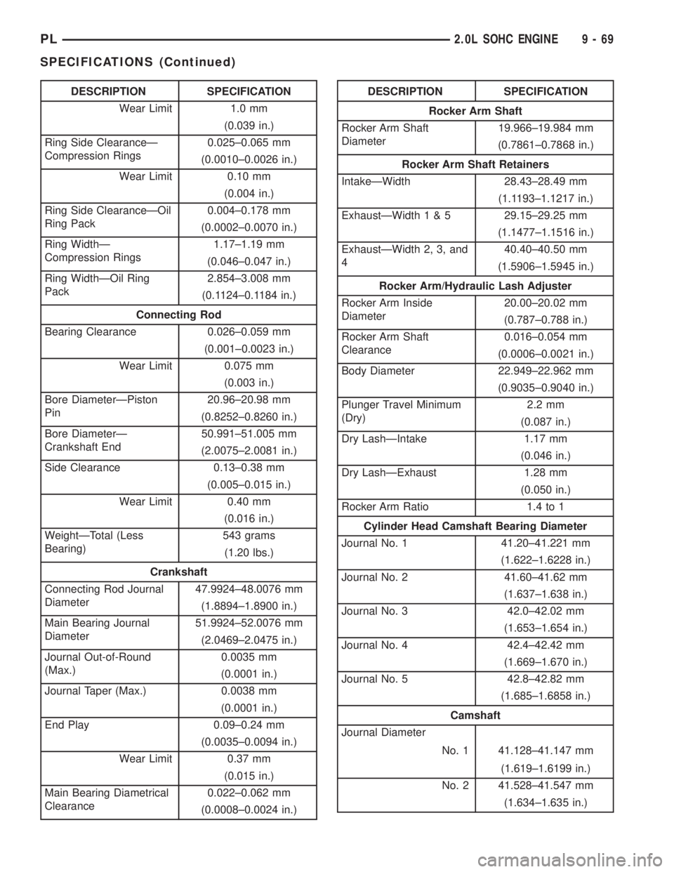
DESCRIPTION SPECIFICATION
Wear Limit 1.0 mm
(0.039 in.)
Ring Side ClearanceÐ
Compression Rings0.025±0.065 mm
(0.0010±0.0026 in.)
Wear Limit 0.10 mm
(0.004 in.)
Ring Side ClearanceÐOil
Ring Pack0.004±0.178 mm
(0.0002±0.0070 in.)
Ring WidthÐ
Compression Rings1.17±1.19 mm
(0.046±0.047 in.)
Ring WidthÐOil Ring
Pack2.854±3.008 mm
(0.1124±0.1184 in.)
Connecting Rod
Bearing Clearance 0.026±0.059 mm
(0.001±0.0023 in.)
Wear Limit 0.075 mm
(0.003 in.)
Bore DiameterÐPiston
Pin20.96±20.98 mm
(0.8252±0.8260 in.)
Bore DiameterÐ
Crankshaft End50.991±51.005 mm
(2.0075±2.0081 in.)
Side Clearance 0.13±0.38 mm
(0.005±0.015 in.)
Wear Limit 0.40 mm
(0.016 in.)
WeightÐTotal (Less
Bearing)543 grams
(1.20 lbs.)
Crankshaft
Connecting Rod Journal
Diameter47.9924±48.0076 mm
(1.8894±1.8900 in.)
Main Bearing Journal
Diameter51.9924±52.0076 mm
(2.0469±2.0475 in.)
Journal Out-of-Round
(Max.)0.0035 mm
(0.0001 in.)
Journal Taper (Max.) 0.0038 mm
(0.0001 in.)
End Play 0.09±0.24 mm
(0.0035±0.0094 in.)
Wear Limit 0.37 mm
(0.015 in.)
Main Bearing Diametrical
Clearance0.022±0.062 mm
(0.0008±0.0024 in.)DESCRIPTION SPECIFICATION
Rocker Arm Shaft
Rocker Arm Shaft
Diameter19.966±19.984 mm
(0.7861±0.7868 in.)
Rocker Arm Shaft Retainers
IntakeÐWidth 28.43±28.49 mm
(1.1193±1.1217 in.)
ExhaustÐWidth1&529.15±29.25 mm
(1.1477±1.1516 in.)
ExhaustÐWidth 2, 3, and
440.40±40.50 mm
(1.5906±1.5945 in.)
Rocker Arm/Hydraulic Lash Adjuster
Rocker Arm Inside
Diameter20.00±20.02 mm
(0.787±0.788 in.)
Rocker Arm Shaft
Clearance0.016±0.054 mm
(0.0006±0.0021 in.)
Body Diameter 22.949±22.962 mm
(0.9035±0.9040 in.)
Plunger Travel Minimum
(Dry)2.2 mm
(0.087 in.)
Dry LashÐIntake 1.17 mm
(0.046 in.)
Dry LashÐExhaust 1.28 mm
(0.050 in.)
Rocker Arm Ratio 1.4 to 1
Cylinder Head Camshaft Bearing Diameter
Journal No. 1 41.20±41.221 mm
(1.622±1.6228 in.)
Journal No. 2 41.60±41.62 mm
(1.637±1.638 in.)
Journal No. 3 42.0±42.02 mm
(1.653±1.654 in.)
Journal No. 4 42.4±42.42 mm
(1.669±1.670 in.)
Journal No. 5 42.8±42.82 mm
(1.685±1.6858 in.)
Camshaft
Journal Diameter
No. 1 41.128±41.147 mm
(1.619±1.6199 in.)
No. 2 41.528±41.547 mm
(1.634±1.635 in.)
PL2.0L SOHC ENGINE 9 - 69
SPECIFICATIONS (Continued)
Page 793 of 1285
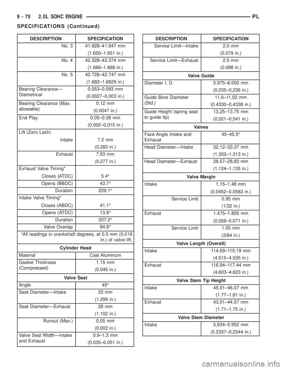
DESCRIPTION SPECIFICATION
No. 3 41.928±41.947 mm
(1.650±1.651 in.)
No. 4 42.328±42.374 mm
(1.666±1.668 in.)
No. 5 42.728±42.747 mm
(1.682±1.6829 in.)
Bearing ClearanceÐ
Diametrical0.053±0.093 mm
(0.0027±0.003 in.)
Bearing Clearance (Max.
allowable)0.12 mm
(0.0047 in.)
End Play 0.05±0.39 mm
(0.002±0.015 in.)
Lift (Zero Lash)
Intake 7.2 mm
(0.283 in.)
Exhaust 7.03 mm
(0.277 in.)
Exhaust Valve Timing*
Closes (ATDC) 5.4É
Opens (BBDC) 43.7É
Duration 229.1É
Intake Valve Timing*
Closes (ABDC) 41.1É
Opens (ATDC) 13.9É
Duration 207.2É
Valve Overlap 84.8É
*All readings in crankshaft degrees, at 0.5 mm (0.019
in.) of valve lift.
Cylinder Head
Material Cast Aluminum
Gasket Thickness
(Compressed)1.15 mm
(0.045 in.)
Valve Seat
Angle 45É
Seat DiameterÐIntake 33 mm
(1.299 in.)
Seat DiameterÐExhaust 28 mm
(1.102 in.)
Runout (Max.) 0.05 mm
(0.002 in.)
Valve Seat WidthÐIntake
and Exhaust0.9±1.3 mm
(0.035±0.051 in.)DESCRIPTION SPECIFICATION
Service LimitÐIntake 2.0 mm
(0.079 in.)
Service LimitÐExhaust 2.5 mm
(0.098 in.)
Valve Guide
Diameter I. D. 5.975±6.000 mm
(0.235±0.236 in.)
Guide Bore Diameter
(Std.)11.0±11.02 mm
(0.4330±0.4338 in.)
Guide Height (spring seat
to guide tip)13.25±13.75 mm
(0.521±0.541 in.)
Valves
Face Angle Intake and
Exhaust45±45.5É
Head DiameterÐIntake 32.12±33.37 mm
(1.303±1.313 in.)
Head DiameterÐExhaust 28.57±28.83 mm
(1.124±1.135 in.)
Valve Margin
Intake 1.15±1.48 mm
(0.0452±0.0583 in.)
Service Limit 0.95 mm
(1/32 in.)
Exhaust 1.475±1.805 mm
(0.058±0.071 in.)
Service Limit 1.05 mm
(3/64 in.)
Valve Length (Overall)
Intake 114.69±115.19 mm
(4.515±4.535 in.)
Exhaust 116.94±117.44 mm
(4.603±4.623 in.)
Valve Stem Tip Height
Intake 45.01±46.07 mm
(1.77±1.81 in.)
Exhaust 43.51±44.57 mm
(1.71±1.75 in.)
Valve Stem Diameter
Intake 5.934±5.952 mm
(0.2337±0.2344 in.)
9 - 70 2.0L SOHC ENGINEPL
SPECIFICATIONS (Continued)
Page 843 of 1285
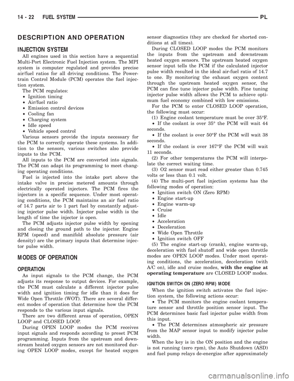
DESCRIPTION AND OPERATION
INJECTION SYSTEM
All engines used in this section have a sequential
Multi-Port Electronic Fuel Injection system. The MPI
system is computer regulated and provides precise
air/fuel ratios for all driving conditions. The Power-
train Control Module (PCM) operates the fuel injec-
tion system.
The PCM regulates:
²Ignition timing
²Air/fuel ratio
²Emission control devices
²Cooling fan
²Charging system
²Idle speed
²Vehicle speed control
Various sensors provide the inputs necessary for
the PCM to correctly operate these systems. In addi-
tion to the sensors, various switches also provide
inputs to the PCM.
All inputs to the PCM are converted into signals.
The PCM can adapt its programming to meet chang-
ing operating conditions.
Fuel is injected into the intake port above the
intake valve in precise metered amounts through
electrically operated injectors. The PCM fires the
injectors in a specific sequence. Under most operat-
ing conditions, the PCM maintains an air fuel ratio
of 14.7 parts air to 1 part fuel by constantly adjust-
ing injector pulse width. Injector pulse width is the
length of time the injector is open.
The PCM adjusts injector pulse width by opening
and closing the ground path to the injector. Engine
RPM (speed) and manifold absolute pressure (air
density) are the primary inputs that determine injec-
tor pulse width.
MODES OF OPERATION
OPERATION
As input signals to the PCM change, the PCM
adjusts its response to output devices. For example,
the PCM must calculate a different injector pulse
width and ignition timing for idle than it does for
Wide Open Throttle (WOT). There are several differ-
ent modes of operation that determine how the PCM
responds to the various input signals.
There are two different areas of operation, OPEN
LOOP and CLOSED LOOP.
During OPEN LOOP modes the PCM receives
input signals and responds according to preset PCM
programming. Inputs from the upstream and down-
stream heated oxygen sensors are not monitored dur-
ing OPEN LOOP modes, except for heated oxygensensor diagnostics (they are checked for shorted con-
ditions at all times).
During CLOSED LOOP modes the PCM monitors
the inputs from the upstream and downstream
heated oxygen sensors. The upstream heated oxygen
sensor input tells the PCM if the calculated injector
pulse width resulted in the ideal air-fuel ratio of 14.7
to one. By monitoring the exhaust oxygen content
through the upstream heated oxygen sensor, the
PCM can fine tune injector pulse width. Fine tuning
injector pulse width allows the PCM to achieve opti-
mum fuel economy combined with low emissions.
For the PCM to enter CLOSED LOOP operation,
the following must occur:
(1) Engine coolant temperature must be over 35ÉF.
²If the coolant is over 35É the PCM will wait 44
seconds.
²If the coolant is over 50ÉF the PCM will wait 38
seconds.
²If the coolant is over 167ÉF the PCM will wait
11 seconds.
(2) For other temperatures the PCM will interpo-
late the correct waiting time.
(3) O2 sensor must read either greater than 0.745
volts or less than 0.1 volt.
(4) The multi-port fuel injection systems has the
following modes of operation:
²Ignition switch ON (Zero RPM)
²Engine start-up
²Engine warm-up
²Cruise
²Idle
²Acceleration
²Deceleration
²Wide Open Throttle
²Ignition switch OFF
(5) The engine start-up (crank), engine warm-up,
deceleration with fuel shutoff and wide open throttle
modes are OPEN LOOP modes. Under most operat-
ing conditions, the acceleration, deceleration (with
A/C on), idle and cruise modes,with the engine at
operating temperatureare CLOSED LOOP modes.
IGNITION SWITCH ON (ZERO RPM) MODE
When the ignition switch activates the fuel injec-
tion system, the following actions occur:
²The PCM monitors the engine coolant tempera-
ture sensor and throttle position sensor input. The
PCM determines basic fuel injector pulse width from
this input.
²The PCM determines atmospheric air pressure
from the MAP sensor input to modify injector pulse
width.
When the key is in the ON position and the engine
is not running (zero rpm), the Auto Shutdown (ASD)
and fuel pump relays de-energize after approximately
14 - 22 FUEL SYSTEMPL