gas mileage DODGE NEON 2000 Service Repair Manual
[x] Cancel search | Manufacturer: DODGE, Model Year: 2000, Model line: NEON, Model: DODGE NEON 2000Pages: 1285, PDF Size: 29.42 MB
Page 198 of 1285

COOLING SYSTEMÐDRAINING
NOTE: Drain, flush, and fill the cooling system at
the mileage or time intervals specified in Group 0,
Lubrication and Maintenance. If the solution is dirty,
rusty, or contains a considerable amount of sedi-
ment; clean and flush with a reliable cooling system
cleaner. Care should be taken in disposing of the
used engine coolant from your vehicle. Check gov-
ernmental regulations for disposal of used engine
coolant.
Without removing radiator pressure cap and
with system not under pressure:
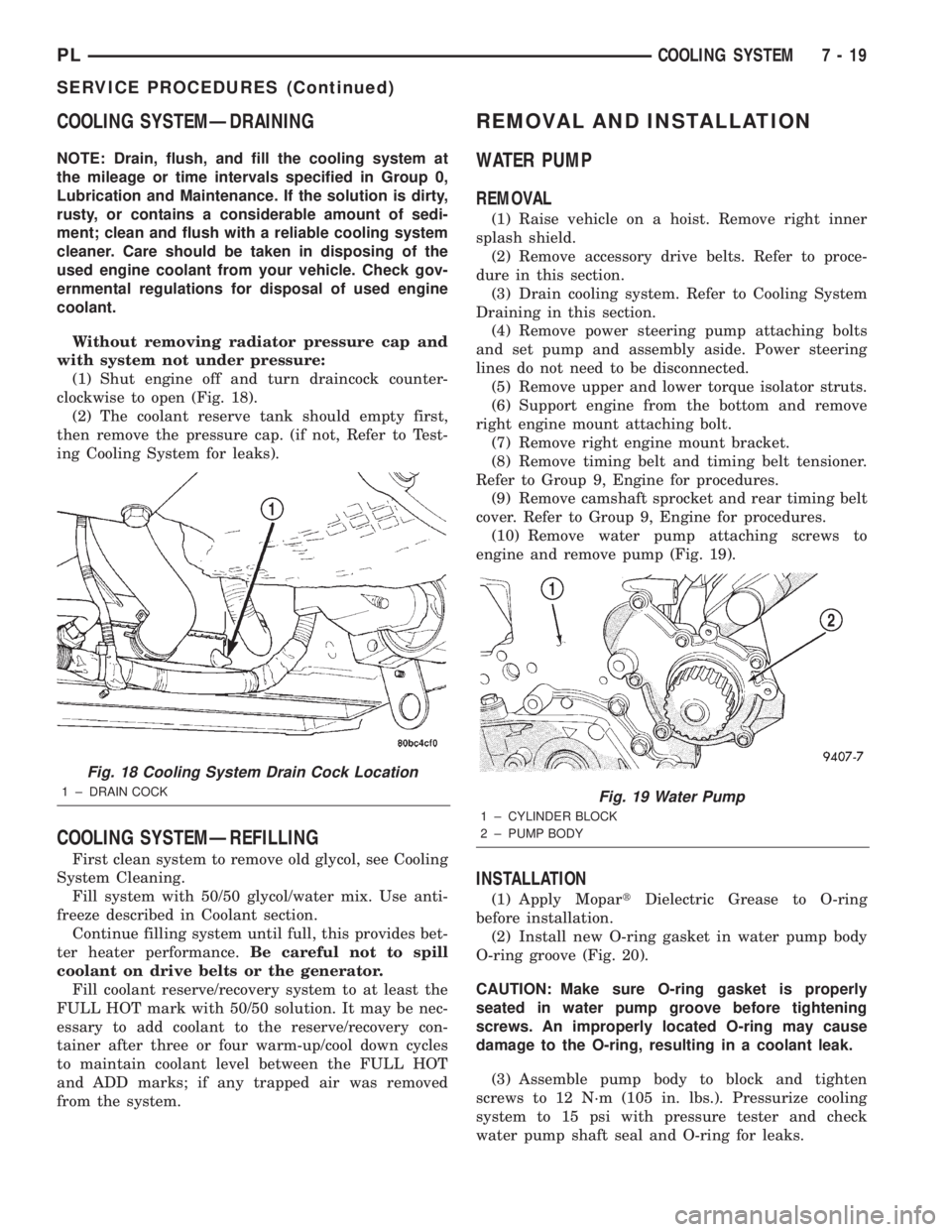
(1) Shut engine off and turn draincock counter-
clockwise to open (Fig. 18).
(2) The coolant reserve tank should empty first,
then remove the pressure cap. (if not, Refer to Test-
ing Cooling System for leaks).
COOLING SYSTEMÐREFILLING
First clean system to remove old glycol, see Cooling
System Cleaning.
Fill system with 50/50 glycol/water mix. Use anti-
freeze described in Coolant section.
Continue filling system until full, this provides bet-
ter heater performance.Be careful not to spill
coolant on drive belts or the generator.
Fill coolant reserve/recovery system to at least the
FULL HOT mark with 50/50 solution. It may be nec-
essary to add coolant to the reserve/recovery con-
tainer after three or four warm-up/cool down cycles
to maintain coolant level between the FULL HOT
and ADD marks; if any trapped air was removed
from the system.
REMOVAL AND INSTALLATION
WATER PUMP
REMOVAL
(1) Raise vehicle on a hoist. Remove right inner
splash shield.
(2) Remove accessory drive belts. Refer to proce-
dure in this section.
(3) Drain cooling system. Refer to Cooling System
Draining in this section.
(4) Remove power steering pump attaching bolts
and set pump and assembly aside. Power steering
lines do not need to be disconnected.
(5) Remove upper and lower torque isolator struts.
(6) Support engine from the bottom and remove
right engine mount attaching bolt.
(7) Remove right engine mount bracket.
(8) Remove timing belt and timing belt tensioner.
Refer to Group 9, Engine for procedures.
(9) Remove camshaft sprocket and rear timing belt
cover. Refer to Group 9, Engine for procedures.
(10) Remove water pump attaching screws to
engine and remove pump (Fig. 19).
INSTALLATION
(1) Apply MopartDielectric Grease to O-ring
before installation.
(2) Install new O-ring gasket in water pump body
O-ring groove (Fig. 20).
CAUTION: Make sure O-ring gasket is properly
seated in water pump groove before tightening
screws. An improperly located O-ring may cause
damage to the O-ring, resulting in a coolant leak.
(3) Assemble pump body to block and tighten
screws to 12 N´m (105 in. lbs.). Pressurize cooling
system to 15 psi with pressure tester and check
water pump shaft seal and O-ring for leaks.
Fig. 18 Cooling System Drain Cock Location
1 ± DRAIN COCKFig. 19 Water Pump
1 ± CYLINDER BLOCK
2 ± PUMP BODY
PLCOOLING SYSTEM 7 - 19
SERVICE PROCEDURES (Continued)
Page 730 of 1285

ENGINE OIL SERVICE
WARNING: NEW OR USED ENGINE OIL CAN BE
IRRITATING TO THE SKIN. AVOID PROLONGED OR
REPEATED SKIN CONTACT WITH ENGINE OIL.
CONTAMINANTS IN USED ENGINE OIL, CAUSED BY
INTERNAL COMBUSTION, CAN BE HAZARDOUS TO
YOUR HEALTH. THOROUGHLY WASH EXPOSED
SKIN WITH SOAP AND WATER. DO NOT WASH
SKIN WITH GASOLINE, DIESEL FUEL, THINNER, OR
SOLVENTS, HEALTH PROBLEMS CAN RESULT. DO
NOT POLLUTE, DISPOSE OF USED ENGINE OIL
PROPERLY. CONTACT YOUR DEALER OR GOVERN-
MENT AGENCY FOR LOCATION OF COLLECTION
CENTER IN YOUR AREA.
ENGINE OIL SPECIFICATION
CAUTION: Do not use non-detergent or straight
mineral oil when adding or changing crankcase
lubricant. Engine failure can result.
API SERVICE GRADE CERTIFIED
Use an engine oil that is API Service Grade Certi-
fied. MOPARtprovides engine oils that conforms to
this service grade.
SAE VISCOSITY
An SAE viscosity grade is used to specify the vis-
cosity of engine oil. Use only, engine oils with multi-
ple viscosities such as 5W-30 or 10W-30. These are
specified with a dual SAE viscosity grade which indi-
cates the cold-to-hot temperature viscosity range.
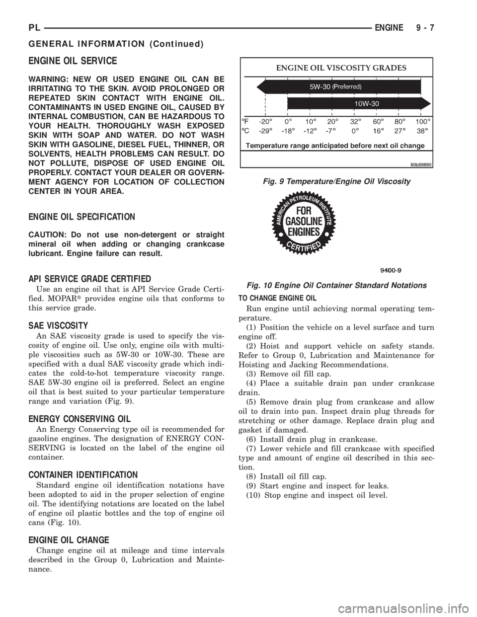
SAE 5W-30 engine oil is preferred. Select an engine
oil that is best suited to your particular temperature
range and variation (Fig. 9).
ENERGY CONSERVING OIL
An Energy Conserving type oil is recommended for
gasoline engines. The designation of ENERGY CON-
SERVING is located on the label of the engine oil
container.
CONTAINER IDENTIFICATION
Standard engine oil identification notations have
been adopted to aid in the proper selection of engine
oil. The identifying notations are located on the label
of engine oil plastic bottles and the top of engine oil
cans (Fig. 10).
ENGINE OIL CHANGE
Change engine oil at mileage and time intervals
described in the Group 0, Lubrication and Mainte-
nance.TO CHANGE ENGINE OIL
Run engine until achieving normal operating tem-
perature.
(1) Position the vehicle on a level surface and turn
engine off.
(2) Hoist and support vehicle on safety stands.
Refer to Group 0, Lubrication and Maintenance for
Hoisting and Jacking Recommendations.
(3) Remove oil fill cap.
(4) Place a suitable drain pan under crankcase
drain.
(5) Remove drain plug from crankcase and allow
oil to drain into pan. Inspect drain plug threads for
stretching or other damage. Replace drain plug and
gasket if damaged.
(6) Install drain plug in crankcase.
(7) Lower vehicle and fill crankcase with specified
type and amount of engine oil described in this sec-
tion.
(8) Install oil fill cap.
(9) Start engine and inspect for leaks.
(10) Stop engine and inspect oil level.
Fig. 9 Temperature/Engine Oil Viscosity
Fig. 10 Engine Oil Container Standard Notations
PLENGINE 9 - 7
GENERAL INFORMATION (Continued)
Page 845 of 1285

²All inputs monitored for proper voltage range.
²All monitored components (refer to the Emission
section for On-Board Diagnostics).
The PCM compares the upstream and downstream
heated oxygen sensor inputs to measure catalytic
convertor efficiency. If the catalyst efficiency drops
below the minimum acceptable percentage, the PCM
stores a diagnostic trouble code in memory.
During certain idle conditions, the PCM may enter
a variable idle speed strategy. During variable idle
speed strategy the PCM adjusts engine speed based
on the following inputs.
²A/C sense
²Battery voltage
²Battery temperature
²Engine coolant temperature
²Engine run time
²Power steering pressure switch
²Vehicle mileage
ACCELERATION MODE
This is a CLOSED LOOP mode. The PCM recog-
nizes an abrupt increase in Throttle Position sensor
output voltage or MAP sensor output voltage as a
demand for increased engine output and vehicle
acceleration. The PCM increases injector pulse width
in response to increased fuel demand.
DECELERATION MODE
This is a CLOSED LOOP mode. During decelera-
tion the following inputs are received by the PCM:
²A/C pressure transducer
²A/C sense
²Battery voltage
²Intake air temperature
²Engine coolant temperature
²Crankshaft position (engine speed)
²Exhaust gas oxygen content (upstream heated
oxygen sensor)
²Knock sensor
²Manifold absolute pressure
²Power steering pressure switch
²Throttle position
²IAC motor control changes in response to MAP
sensor feedback.
The PCM may receive a closed throttle input from
the Throttle Position Sensor (TPS) when it senses an
abrupt decrease in manifold pressure. This indicates
a hard deceleration. In response, the PCM may
momentarily turn off the injectors. This helps
improve fuel economy, emissions and engine braking.
If decel fuel shutoff is detected, downstream oxy-
gen sensor diagnostics is performed.WIDE-OPEN-THROTTLE MODE
This is an OPEN LOOP mode. During wide-open-
throttle operation, the following inputs are received
by the PCM:
²Intake air temperature
²Engine coolant temperature
²Engine speed
²Knock sensor
²Manifold absolute pressure
²Throttle position
When the PCM senses a wide-open-throttle condi-
tion through the Throttle Position Sensor (TPS) it de-
energizes the A/C compressor clutch relay. This
disables the air conditioning system.
The PCM does not monitor the heated oxygen sen-
sor inputs during wide-open-throttle operation except
for downstream heated oxygen sensor and both
shorted diagnostics. The PCM adjusts injector pulse
width to supply a predetermined amount of addi-
tional fuel.
IGNITION SWITCH OFF MODE
When the operator turns the ignition switch to the
OFF position, the following occurs:
²All outputs are turned off, unless 02 Heater
Monitor test is being run. Refer to the Emission sec-
tion for On-Board Diagnostics.
²No inputs are monitored except for the heated
oxygen sensors. The PCM monitors the heating ele-
ments in the oxygen sensors and then shuts down.
SYSTEM DIAGNOSIS
OPERATION
The PCM can test many of its own input and out-
put circuits. If the PCM senses a fault in a major
system, the PCM stores a Diagnostic Trouble Code
(DTC) in memory.
For DTC information see On-Board Diagnostics.
POWER DISTRIBUTION CENTER
The Power Distribution Center (PDC) is located
next to the battery (Fig. 1). The PDC contains the
starter relay, radiator fan relay, A/C compressor
clutch relay, auto shutdown relay, fuel pump relay
and several fuses.
POWERTRAIN CONTROL MODULE
The Powertrain Control Module (PCM) is a digital
computer containing a microprocessor (Fig. 2). The
PCM receives input signals from various switches
and sensors that are referred to as PCM Inputs.
Based on these inputs, the PCM adjusts various
engine and vehicle operations through devices that
are referred to as PCM Outputs.
PCM Inputs:
14 - 24 FUEL SYSTEMPL
DESCRIPTION AND OPERATION (Continued)