ground clearance DODGE NEON 2000 Service Repair Manual
[x] Cancel search | Manufacturer: DODGE, Model Year: 2000, Model line: NEON, Model: DODGE NEON 2000Pages: 1285, PDF Size: 29.42 MB
Page 9 of 1285
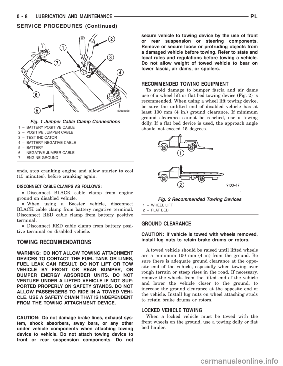
onds, stop cranking engine and allow starter to cool
(15 minutes), before cranking again.
DISCONNECT CABLE CLAMPS AS FOLLOWS:
²Disconnect BLACK cable clamp from engine
ground on disabled vehicle.
²When using a Booster vehicle, disconnect
BLACK cable clamp from battery negative terminal.
Disconnect RED cable clamp from battery positive
terminal.
²Disconnect RED cable clamp from battery posi-
tive terminal on disabled vehicle.
TOWING RECOMMENDATIONS
WARNING: DO NOT ALLOW TOWING ATTACHMENT
DEVICES TO CONTACT THE FUEL TANK OR LINES,
FUEL LEAK CAN RESULT. DO NOT LIFT OR TOW
VEHICLE BY FRONT OR REAR BUMPER, OR
BUMPER ENERGY ABSORBER UNITS. DO NOT
VENTURE UNDER A LIFTED VEHICLE IF NOT SUP-
PORTED PROPERLY ON SAFETY STANDS. DO NOT
ALLOW PASSENGERS TO RIDE IN A TOWED VEHI-
CLE. USE A SAFETY CHAIN THAT IS INDEPENDENT
FROM THE TOWING ATTACHMENT DEVICE.
CAUTION: Do not damage brake lines, exhaust sys-
tem, shock absorbers, sway bars, or any other
under vehicle components when attaching towing
device to vehicle. Do not attach towing device to
front or rear suspension components. Do notsecure vehicle to towing device by the use of front
or rear suspension or steering components.
Remove or secure loose or protruding objects from
a damaged vehicle before towing. Refer to state and
local rules and regulations before towing a vehicle.
Do not allow weight of towed vehicle to bear on
lower fascia, air dams, or spoilers.
RECOMMENDED TOWING EQUIPMENT
To avoid damage to bumper fascia and air dams
use of a wheel lift or flat bed towing device (Fig. 2) is
recommended. When using a wheel lift towing device,
be sure the unlifted end of disabled vehicle has at
least 100 mm (4 in.) ground clearance. If minimum
ground clearance cannot be reached, use a towing
dolly. If a flat bed device is used, the approach angle
should not exceed 15 degrees.
GROUND CLEARANCE
CAUTION: If vehicle is towed with wheels removed,
install lug nuts to retain brake drums or rotors.
A towed vehicle should be raised until lifted wheels
are a minimum 100 mm (4 in) from the ground. Be
sure there is adequate ground clearance at the oppo-
site end of the vehicle, especially when towing over
rough terrain or steep rises in the road. If necessary,
remove the wheels from the lifted end of the vehicle
and lower the vehicle closer to the ground, to
increase the ground clearance at the opposite end of
the vehicle. Install lug nuts on wheel attaching studs
to retain brake drums or rotors.
LOCKED VEHICLE TOWING
When a locked vehicle must be towed with the
front wheels on the ground, use a towing dolly or flat
bed hauler.
Fig. 1 Jumper Cable Clamp Connections
1 ± BATTERY POSITIVE CABLE
2 ± POSITIVE JUMPER CABLE
3 ± TEST INDICATOR
4 ± BATTERY NEGATIVE CABLE
5 ± BATTERY
6 ± NEGATIVE JUMPER CABLE
7 ± ENGINE GROUND
Fig. 2 Recommended Towing Devices
1 ± WHEEL LIFT
2 ± FLAT BED
0 - 8 LUBRICATION AND MAINTENANCEPL
SERVICE PROCEDURES (Continued)
Page 155 of 1285
junction block. A label on the underside of the PDC
cover identifies the locations of the ABS fuses.
(2) Inspect the 25-way electrical connector at the
CAB for damaged, spread, or backed-out wiring ter-
minals. Verify that the 25-way connector is fully
inserted in the socket of the CAB. Be sure that wires
are not stretched tight or pulled out of the connector.
(3) Verify that all the wheel speed sensor connec-
tions are secure.
(4) Look for poor mating of connector halves or ter-
minals not fully seated in the connector body.
(5)
Check for improperly formed or damaged termi-
nals. All connector terminals in a suspect circuit should
be carefully reformed to increase contact tension.
(6) Look for poor terminal-to-wire connections.
This requires removing the terminal from the connec-
tor body to inspect it.
(7) Verify pin presence in the connector assembly
(8) Check for proper ground connections. Check all
ground connections for signs of corrosion, loose fas-
teners, or other potential defects. Refer to the wiring
diagrams for ground locations.
(9) Look for problems with the main power sources
of the vehicle. Inspect the battery, generator, ignition
circuits and other related relays and fuses.
If a visual check does not find the cause of the
problem, operate the car in an attempt to duplicate
the condition and record any trouble codes.
Most failures of the ABS disable the ABS function
for the entire ignition cycle even if the fault clears
before key-off. There are some failure conditions,
however, that allow ABS operation to resume during
the ignition cycle in which the trouble occurred even
if the trouble conditions are no longer present.
The following trouble conditions may result in
intermittent illumination of the amber ABS warning
lamp.
²Low system voltage. If Low System Voltage is
detected by the CAB, the CAB will turn on the ABS
Warning Lamp until normal system voltage is
achieved. Once normal voltage is seen at the CAB,
normal operation resumes.
²High system voltage. If high system voltage is
detected by the CAB, the CAB will turn on the
Amber ABS Warning Lamp until normal system volt-
age is achieved. Once normal voltage is again
detected by the CAB, normal ABS operation resumes.
Additional possible causes that may result in the
illumination of the amber ABS warning lamp are as
follows:
²Any condition that interrupts electrical current
to the CAB may cause the amber ABS warning lamp
to turn on intermittently.
²If PCI communication between the body control-
ler and the CAB is interrupted, the body controller
can turn on the amber ABS warning lamp.
TONE WHEEL
Tone wheels can cause erratic wheel speed sensor
signals. Inspect tone wheels for the following possible
causes:
²missing, chipped, or broken teeth
²contact with the wheel speed sensor
²wheel speed sensor to tone wheel alignment
²wheel speed sensor to tone wheel clearance
²excessive tone wheel runout
²tone wheel loose on its mounting surface
If a front tone wheel is found to need replacement,
the drive shaft must be replaced. No attempt should
be made to replace just the tone wheel. Refer to the
DIFFERENTIAL AND DRIVELINE group in this
service manual for removal and installation.
If a rear tone wheel is found to need replacement,
the rear hub and bearing must be replaced. No
attempt should be made to replace just the tone
wheel. Refer to the SUSPENSION group in this ser-
vice manual for removal and installation.
If wheel speed sensor to tone wheel contact is evi-
dent, determine the cause and correct it before
replacing the wheel speed sensor or tone wheel.
Check the gap between the speed sensor head and
the tone wheel to ensure it is within specifications.
Refer to SPECIFICATIONS in this section of the ser-
vice manual for the minimum and maximum wheel
speed sensor to tone wheel clearance.
Excessive wheel speed sensor runout can cause
erratic wheel speed sensor signals. Refer to SPECI-
FICATIONS in this section of the service manual for
the maximum allowed tone wheel runout. If tone
wheel runout is excessive, determine if it is caused
by a defect in the driveshaft assembly or hub and
bearing. Replace as necessary.
Tone wheels are pressed onto their mounting sur-
faces and should not rotate independently from the
mounting surface. Replacement of the front drive-
shaft or rear hub and bearing is necessary.
BRAKE FLUID CONTAMINATION
Indications of fluid contamination are swollen or
deteriorated rubber parts. Swelling indicates the
presence of petroleum in the brake fluid.
To test for contamination, put a small amount of
drained brake fluid in clear glass jar. If the fluid sep-
arates into layers, there is mineral oil or other fluid
contamination of the brake fluid.
If the brake fluid is contaminated, drain and thor-
oughly flush the brake system. Replace all the rubber
parts or components containing rubber coming into
contact with the brake fluid including: the master
cylinder; proportioning valves; caliper seals; wheel
cylinder seals; ABS hydraulic control unit; and all
hydraulic fluid hoses.
5 - 76 BRAKESPL
DIAGNOSIS AND TESTING (Continued)
Page 174 of 1285
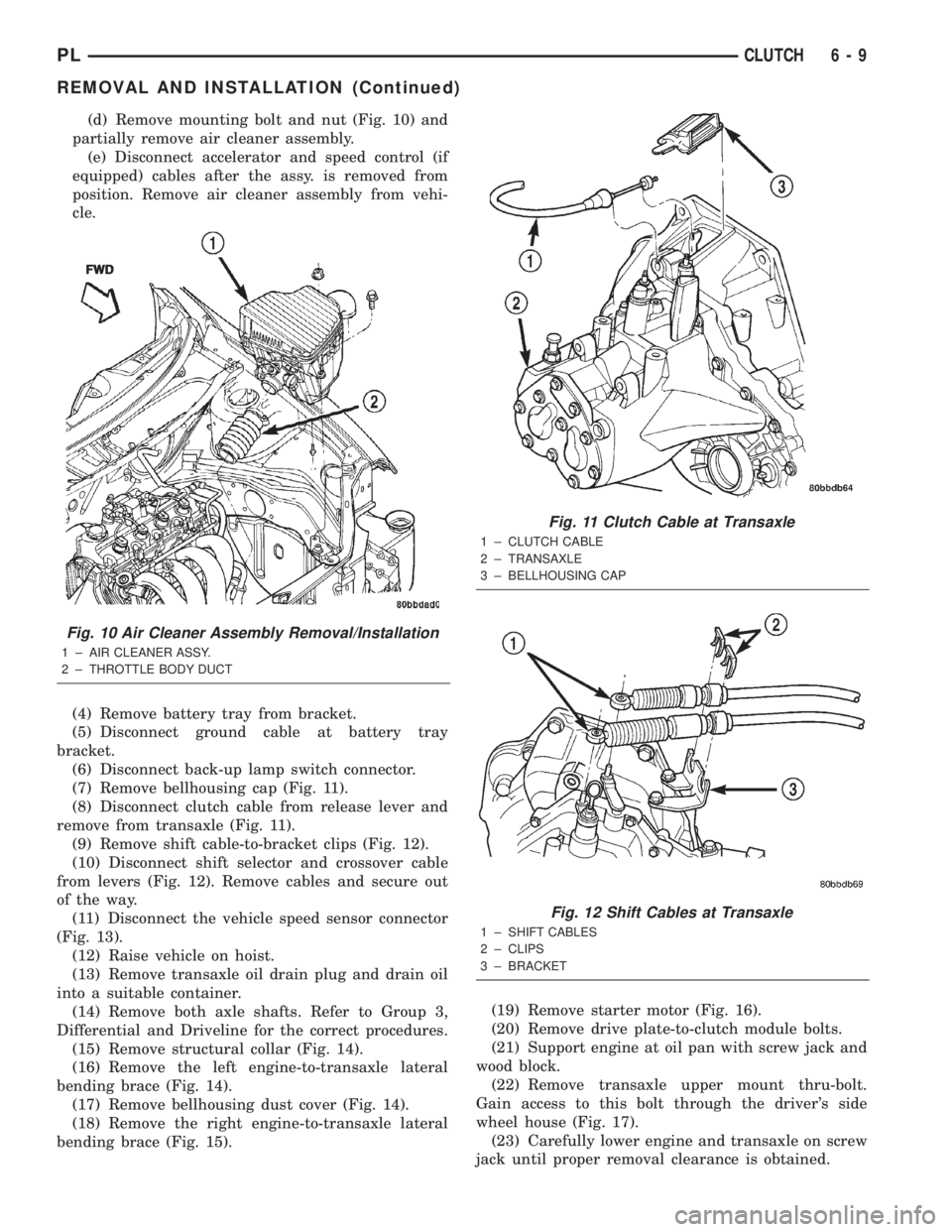
(d) Remove mounting bolt and nut (Fig. 10) and
partially remove air cleaner assembly.
(e) Disconnect accelerator and speed control (if
equipped) cables after the assy. is removed from
position. Remove air cleaner assembly from vehi-
cle.
(4) Remove battery tray from bracket.
(5) Disconnect ground cable at battery tray
bracket.
(6) Disconnect back-up lamp switch connector.
(7) Remove bellhousing cap (Fig. 11).
(8) Disconnect clutch cable from release lever and
remove from transaxle (Fig. 11).
(9) Remove shift cable-to-bracket clips (Fig. 12).
(10) Disconnect shift selector and crossover cable
from levers (Fig. 12). Remove cables and secure out
of the way.
(11) Disconnect the vehicle speed sensor connector
(Fig. 13).
(12) Raise vehicle on hoist.
(13) Remove transaxle oil drain plug and drain oil
into a suitable container.
(14) Remove both axle shafts. Refer to Group 3,
Differential and Driveline for the correct procedures.
(15) Remove structural collar (Fig. 14).
(16) Remove the left engine-to-transaxle lateral
bending brace (Fig. 14).
(17) Remove bellhousing dust cover (Fig. 14).
(18) Remove the right engine-to-transaxle lateral
bending brace (Fig. 15).(19) Remove starter motor (Fig. 16).
(20) Remove drive plate-to-clutch module bolts.
(21) Support engine at oil pan with screw jack and
wood block.
(22) Remove transaxle upper mount thru-bolt.
Gain access to this bolt through the driver's side
wheel house (Fig. 17).
(23) Carefully lower engine and transaxle on screw
jack until proper removal clearance is obtained.
Fig. 10 Air Cleaner Assembly Removal/Installation
1 ± AIR CLEANER ASSY.
2 ± THROTTLE BODY DUCTFWD
Fig. 11 Clutch Cable at Transaxle
1 ± CLUTCH CABLE
2 ± TRANSAXLE
3 ± BELLHOUSING CAP
Fig. 12 Shift Cables at Transaxle
1 ± SHIFT CABLES
2 ± CLIPS
3 ± BRACKET
PLCLUTCH 6 - 9
REMOVAL AND INSTALLATION (Continued)
Page 801 of 1285
DIAGNOSIS AND TESTING
EXHAUST SYSTEM DIAGNOSIS CHART
CONDITION POSSIBLE CAUSES CORRECTION
EXCESSIVE
EXHAUST NOISE
(UNDER HOOD)1. Exhaust manifold cracked or broken. 1. Replace manifold.
2. Manifold to cylinder head leak. 2. Tighten manifold and/or replace gasket.
3. Exhaust Flex joint to manifold leak. 3. Tighten fasteners or replace gasket.
4. Exhaust flex joint. 4. Replace catalytic converter assembly.
5. Pipe and shell noise from front exhaust
pipe.5. Characteristic of single wall pipes.
EXCESSIVE
EXHAUST NOISE1. Leaks at pipe joints. 1. Tighten or replace clamps at leaking
joints.
2. Burned, blown, or rusted out exhaust
pipe or muffler.2. Replace muffler or exhaust pipes.
3. Restriction in muffler or tailpipe. 3. Remove restriction, if possible or replace
as necessary.
4. Catalytic converter material in muffler. 4. Replace muffler and converter assembly.
Check fuel injection and ignition systems for
proper operation.
REMOVAL AND INSTALLATION
EXHAUST PIPE AND MUFFLER
REMOVAL
WARNING: THE NORMAL OPERATING TEMPERA-
TURE OF THE EXHAUST SYSTEM IS VERY HIGH.
THEREFORE, NEVER WORK AROUND OR ATTEMPT
TO SERVICE ANY PART OF THE EXHAUST SYSTEM
UNTIL IT IS COOLED. SPECIAL CARE SHOULD BE
TAKEN WHEN WORKING NEAR THE CATALYTIC
CONVERTER. THE TEMPERATURE OF THE CON-
VERTER RISES TO A HIGH LEVEL AFTER A SHORT
PERIOD OF ENGINE OPERATING TIME.
(1) Raise vehicle on hoist and apply penetrating oil
to band clamp fastener of component being removed.
NOTE: Do not use petroleum-based lubricants
when removing/installing muffler or exhaust pipe
isolators as it may compromise the life of the part.
A suitable substitute is a mixture of liquid dish
soap and water.
(2) Remove exhaust system ground strap.
(3) Loosen band clamp and remove support isola-
tors at muffler. Remove muffler from exhaust pipe
(Fig. 7).(4) Loosen band clamp at the catalytic converter to
intermediate pipe joint (Fig. 7)
(5) Remove intermediate pipe support isolator.
Separate at slip joint and remove intermediate pipe
(Fig. 7).
(6) Clean ends of pipes and muffler to assure mat-
ing of all parts. Discard broken or worn isolators,
rusted or overused clamps, supports, and attaching
parts.
NOTE: When replacement is required on any com-
ponent of the exhaust system, you must use origi-
nal equipment parts (or their equivalent).
INSTALLATION
When assembling exhaust systemdo nottighten
clamps until components are aligned and clearances
are checked.
(1) Assemble intermediate pipe to catalytic con-
verter and the isolator support to the underbody (Fig.
7).
(2) Install the muffler to intermediate pipe and the
isolator supports to the underbody.
(3) Working from the front of system; align each
component to maintain position and proper clearance
with underbody parts (Fig. 9). Tighten band clamps
to 47 N´m (35 ft. lbs.) (Fig. 8).
11 - 4 EXHAUST SYSTEMPL
Page 805 of 1285
(2) Install exhaust manifold support bracket (Fed-
eral and LEV only). Tighten M10 bolt to 54 N´m (40
ft. lbs.), M12 bolt to 95 N´m (70 ft. lbs.), and nut to
28 N´m (250 in. lbs.).
(3) Install bolt attaching manifold support bracket
to the heat shield (Federal and LEV only). Tighten
bolt to 28 N´m (250 in. lbs.).
(4) Assemble muffler and exhaust pipe to catalytic
converter. Install muffler and pipe support isolators
to the underbody.
(5) Tighten the catalytic converter to exhaust man-
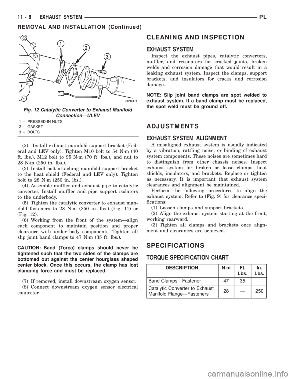
ifold fasteners to 28 N´m (250 in. lbs.) (Fig. 11) or
(Fig. 12).
(6) Working from the front of the systemÐalign
each component to maintain position and proper
clearance with under body components. Tighten all
slip joint band clamps to 47 N´m (35 ft. lbs.).
CAUTION: Band (Torca) clamps should never be
tightened such that the two sides of the clamps are
bottomed out against the center hourglass shaped
center block. Once this occurs, the clamp has lost
clamping force and must be replaced.
(7) If removed, install downstream oxygen sensor.
(8) Connect downstream oxygen sensor electrical
connector.
CLEANING AND INSPECTION
EXHAUST SYSTEM
Inspect the exhaust pipes, catalytic converters,
muffler, and resonators for cracked joints, broken
welds and corrosion damage that would result in a
leaking exhaust system. Inspect the clamps, support
brackets, and insulators for cracks and corrosion
damage.
NOTE: Slip joint band clamps are spot welded to
exhaust system. If a band clamp must be replaced,
the spot weld must be ground off.
ADJUSTMENTS
EXHAUST SYSTEM ALIGNMENT
A misaligned exhaust system is usually indicated
by a vibration, rattling noise, or binding of exhaust
system components. These noises are sometimes hard
to distinguish from other chassis noises. Inspect
exhaust system for broken or loose clamps, heat
shields, insulators, and brackets. Replace or tighten
as necessary. It is important that exhaust system
clearances and alignment be maintained.
Perform the following procedures to align the
exhaust system. Refer to (Fig. 9) for clearance speci-
fications:
(1) Loosen clamps and support brackets.
(2) Align the exhaust system starting at the front,
working rearward.
(3) Tighten all clamps and brackets once align-
ment and clearances are achieved.
SPECIFICATIONS
TORQUE SPECIFICATION CHART
Fig. 12 Catalytic Converter to Exhaust Manifold
ConnectionÐULEV
1 ± PRESSED-IN NUTS
2 ± GASKET
3 ± BOLTS
DESCRIPTION N´m Ft.
Lbs.In.
Lbs.
Band ClampsÐFastener 47 35 Ð
Catalytic Converter to Exhaust
Manifold FlangeÐFasteners28 Ð 250
11 - 8 EXHAUST SYSTEMPL
REMOVAL AND INSTALLATION (Continued)
Page 929 of 1285
(23) Carefully lower engine and transaxle on screw
jack until proper removal clearance is obtained.
(24) Obtain a helper to assist in holding transaxle
while removing transaxle-to-engine mounting bolts
(Fig. 44).(25) Remove transaxle from vehicle (Fig. 44).
(26) If installing a new or replacement transaxle,
remove the upper mount as shown in (Fig. 45), trans-
fer to the replacement unit and torque all bolts to 68
N´m (50 ft. lbs.) torque.
INSTALLATION
(1) Install clutch module onto input shaft. Install
transaxle into position.
(2) Install transaxle-to-engine mounting bolts (Fig.
44) and tighten to 95 N´m (70 ft. lbs.) torque.
(3) Raise engine and transaxle with screw jack
until through hole in upper mount aligns with hole
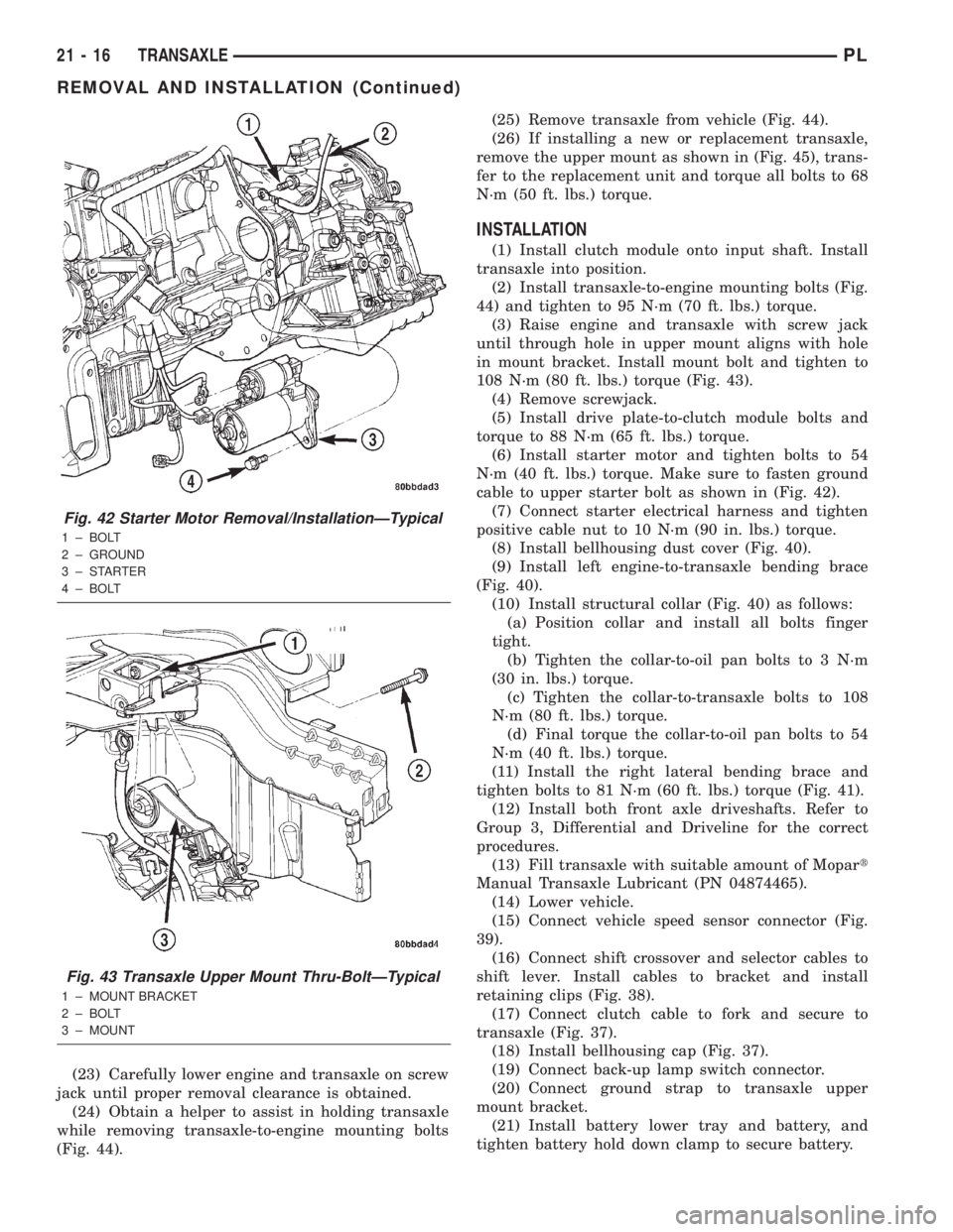
in mount bracket. Install mount bolt and tighten to
108 N´m (80 ft. lbs.) torque (Fig. 43).
(4) Remove screwjack.
(5) Install drive plate-to-clutch module bolts and
torque to 88 N´m (65 ft. lbs.) torque.
(6) Install starter motor and tighten bolts to 54
N´m (40 ft. lbs.) torque. Make sure to fasten ground
cable to upper starter bolt as shown in (Fig. 42).
(7) Connect starter electrical harness and tighten
positive cable nut to 10 N´m (90 in. lbs.) torque.
(8) Install bellhousing dust cover (Fig. 40).
(9) Install left engine-to-transaxle bending brace
(Fig. 40).
(10) Install structural collar (Fig. 40) as follows:
(a) Position collar and install all bolts finger
tight.
(b) Tighten the collar-to-oil pan bolts to 3 N´m
(30 in. lbs.) torque.
(c) Tighten the collar-to-transaxle bolts to 108
N´m (80 ft. lbs.) torque.
(d) Final torque the collar-to-oil pan bolts to 54
N´m (40 ft. lbs.) torque.
(11) Install the right lateral bending brace and
tighten bolts to 81 N´m (60 ft. lbs.) torque (Fig. 41).
(12) Install both front axle driveshafts. Refer to
Group 3, Differential and Driveline for the correct
procedures.
(13) Fill transaxle with suitable amount of Mopart
Manual Transaxle Lubricant (PN 04874465).
(14) Lower vehicle.
(15) Connect vehicle speed sensor connector (Fig.
39).
(16) Connect shift crossover and selector cables to
shift lever. Install cables to bracket and install
retaining clips (Fig. 38).
(17) Connect clutch cable to fork and secure to
transaxle (Fig. 37).
(18) Install bellhousing cap (Fig. 37).
(19) Connect back-up lamp switch connector.
(20) Connect ground strap to transaxle upper
mount bracket.
(21) Install battery lower tray and battery, and
tighten battery hold down clamp to secure battery.
Fig. 42 Starter Motor Removal/InstallationÐTypical
1 ± BOLT
2 ± GROUND
3±STARTER
4 ± BOLT
Fig. 43 Transaxle Upper Mount Thru-BoltÐTypical
1 ± MOUNT BRACKET
2 ± BOLT
3 ± MOUNT
21 - 16 TRANSAXLEPL
REMOVAL AND INSTALLATION (Continued)
Page 999 of 1285
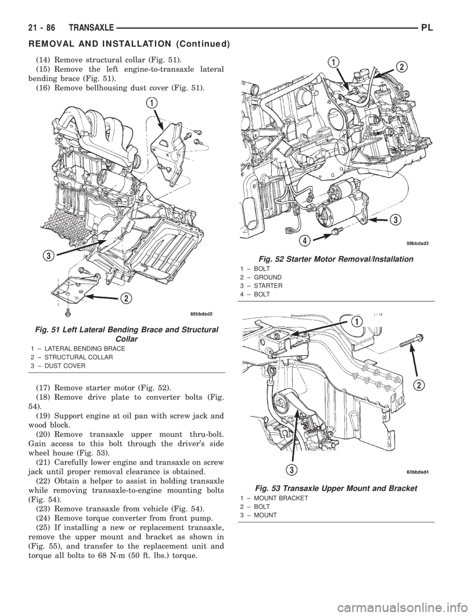
(14) Remove structural collar (Fig. 51).
(15) Remove the left engine-to-transaxle lateral
bending brace (Fig. 51).
(16) Remove bellhousing dust cover (Fig. 51).
(17) Remove starter motor (Fig. 52).
(18) Remove drive plate to converter bolts (Fig.
54).
(19) Support engine at oil pan with screw jack and
wood block.
(20) Remove transaxle upper mount thru-bolt.
Gain access to this bolt through the driver's side
wheel house (Fig. 53).
(21) Carefully lower engine and transaxle on screw
jack until proper removal clearance is obtained.
(22) Obtain a helper to assist in holding transaxle
while removing transaxle-to-engine mounting bolts
(Fig. 54).
(23) Remove transaxle from vehicle (Fig. 54).
(24) Remove torque converter from front pump.
(25) If installing a new or replacement transaxle,
remove the upper mount and bracket as shown in
(Fig. 55), and transfer to the replacement unit and
torque all bolts to 68 N´m (50 ft. lbs.) torque.
Fig. 51 Left Lateral Bending Brace and Structural
Collar
1 ± LATERAL BENDING BRACE
2 ± STRUCTURAL COLLAR
3 ± DUST COVER
Fig. 52 Starter Motor Removal/Installation
1 ± BOLT
2 ± GROUND
3±STARTER
4 ± BOLT
Fig. 53 Transaxle Upper Mount and Bracket
1 ± MOUNT BRACKET
2 ± BOLT
3 ± MOUNT
21 - 86 TRANSAXLEPL
REMOVAL AND INSTALLATION (Continued)