door lock DODGE NEON 2000 Service Repair Manual
[x] Cancel search | Manufacturer: DODGE, Model Year: 2000, Model line: NEON, Model: DODGE NEON 2000Pages: 1285, PDF Size: 29.42 MB
Page 1 of 1285
GROUP TAB LOCATORINIntroductionINaIntroduction0Lubrication and Maintenance2Suspension3Differential and Driveline5Brakes6Clutch7Cooling8ABattery8BStarting8CCharging System8DIgnition System8EInstrument Panel and Systems8EaInstrument Panel and Systems8FAudio System8GHorns8HVehicle Speed Control System8JTurn Signal and Flashers8KWindshield Wipers and Washers8LLamps8LaLamps8MRestraint System8NElectrically Heated Systems8OPower Distribution Systems8PPower Door Locks8QImmobilizer System8SPower Windows8TPower Mirrors8TaPower Mirrors8UChime Warning/Reminder System8WWiring Diagrams - LHD and RHD9Engine11Exhaust System13Frame and Bumpers14Fuel System19Steering21Transaxle22Tires and Wheels23Body24Heating and Air Conditioning24aHeating and Air Conditioning25Emission Control Systems
Page 249 of 1285
DESCRIPTION AND OPERATION
HEADLAMP SWITCH
The headlamp switch is part of the Multi-Function
Switch. Refer to Group 8J, Turn Signal and Flasher
for the Multi-Function Switch Test, Removal and
Installation procedures.
INSTRUMENT CLUSTER
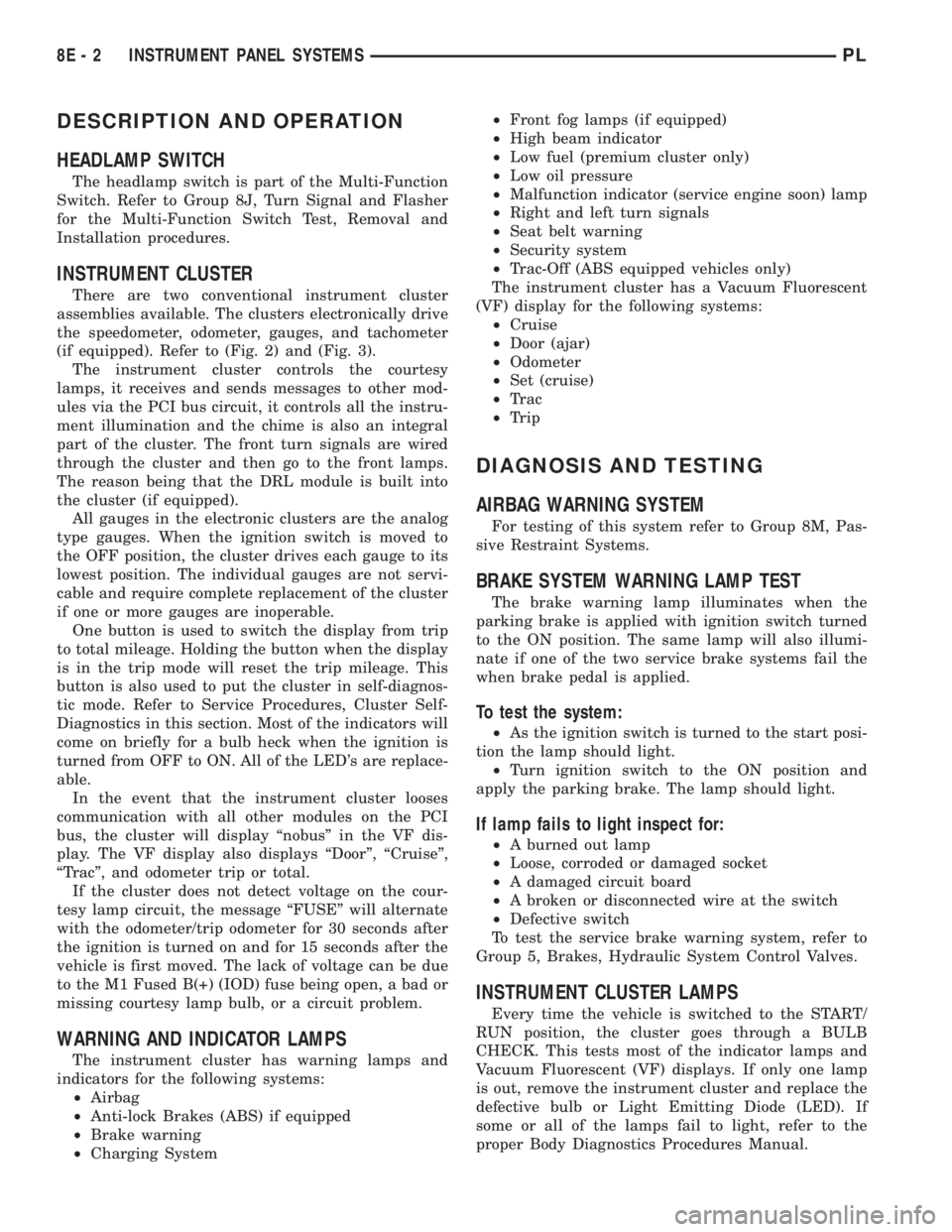
There are two conventional instrument cluster
assemblies available. The clusters electronically drive
the speedometer, odometer, gauges, and tachometer
(if equipped). Refer to (Fig. 2) and (Fig. 3).
The instrument cluster controls the courtesy
lamps, it receives and sends messages to other mod-
ules via the PCI bus circuit, it controls all the instru-
ment illumination and the chime is also an integral
part of the cluster. The front turn signals are wired
through the cluster and then go to the front lamps.
The reason being that the DRL module is built into
the cluster (if equipped).
All gauges in the electronic clusters are the analog
type gauges. When the ignition switch is moved to
the OFF position, the cluster drives each gauge to its
lowest position. The individual gauges are not servi-
cable and require complete replacement of the cluster
if one or more gauges are inoperable.
One button is used to switch the display from trip
to total mileage. Holding the button when the display
is in the trip mode will reset the trip mileage. This
button is also used to put the cluster in self-diagnos-
tic mode. Refer to Service Procedures, Cluster Self-
Diagnostics in this section. Most of the indicators will
come on briefly for a bulb heck when the ignition is
turned from OFF to ON. All of the LED's are replace-
able.
In the event that the instrument cluster looses
communication with all other modules on the PCI
bus, the cluster will display ªnobusº in the VF dis-
play. The VF display also displays ªDoorº, ªCruiseº,
ªTracº, and odometer trip or total.
If the cluster does not detect voltage on the cour-
tesy lamp circuit, the message ªFUSEº will alternate
with the odometer/trip odometer for 30 seconds after
the ignition is turned on and for 15 seconds after the
vehicle is first moved. The lack of voltage can be due
to the M1 Fused B(+) (IOD) fuse being open, a bad or
missing courtesy lamp bulb, or a circuit problem.
WARNING AND INDICATOR LAMPS
The instrument cluster has warning lamps and
indicators for the following systems:
²Airbag
²Anti-lock Brakes (ABS) if equipped
²Brake warning
²Charging System²Front fog lamps (if equipped)
²High beam indicator
²Low fuel (premium cluster only)
²Low oil pressure
²Malfunction indicator (service engine soon) lamp
²Right and left turn signals
²Seat belt warning
²Security system
²Trac-Off (ABS equipped vehicles only)
The instrument cluster has a Vacuum Fluorescent
(VF) display for the following systems:
²Cruise
²Door (ajar)
²Odometer
²Set (cruise)
²Trac
²Trip
DIAGNOSIS AND TESTING
AIRBAG WARNING SYSTEM
For testing of this system refer to Group 8M, Pas-
sive Restraint Systems.
BRAKE SYSTEM WARNING LAMP TEST
The brake warning lamp illuminates when the
parking brake is applied with ignition switch turned
to the ON position. The same lamp will also illumi-
nate if one of the two service brake systems fail the
when brake pedal is applied.
To test the system:
²As the ignition switch is turned to the start posi-
tion the lamp should light.
²Turn ignition switch to the ON position and
apply the parking brake. The lamp should light.
If lamp fails to light inspect for:
²A burned out lamp
²Loose, corroded or damaged socket
²A damaged circuit board
²A broken or disconnected wire at the switch
²Defective switch
To test the service brake warning system, refer to
Group 5, Brakes, Hydraulic System Control Valves.
INSTRUMENT CLUSTER LAMPS
Every time the vehicle is switched to the START/
RUN position, the cluster goes through a BULB
CHECK. This tests most of the indicator lamps and
Vacuum Fluorescent (VF) displays. If only one lamp
is out, remove the instrument cluster and replace the
defective bulb or Light Emitting Diode (LED). If
some or all of the lamps fail to light, refer to the
proper Body Diagnostics Procedures Manual.
8E - 2 INSTRUMENT PANEL SYSTEMSPL
Page 253 of 1285
(6) Set base aside and remove base mount ring.
INSTALLATION
(1) Position mount ring to the instrument panel
and feed the wires through ring. Index the cap and
the mount ring with the index tab at 9 o'clock to the
key in the instrument panel. Install the ring.
(2) Connect wires to base. Orient base alignment
rib at 11 o'clock to mate the groove in mount ring at
the same location
(3) Push base into the bezel till it locks.
(4) Install cigar lighter cap and check operation of
element.
GLOVE BOX DOOR/BIN
REMOVAL
(1) Open front passenger door.
(2) Remove three glove box door hinge screws.
(3) Open glove box and remove assembly from
vehicle.
(4) Remove eight screws retaining glove box door
to bin assembly.
(5) Separate glove box door from bin and remove.
INSTALLATION
For installation, reverse the above procedures.
GLOVE BOX DOOR/BIN
REMOVAL
(1) Open front passenger door.
(2) Remove three glove box door hinge screws.
(3) Open glove box and remove assembly from
vehicle.
(4) Remove eight screws retaining glove box door
to bin assembly.(5) Separate glove box door from bin and remove.
INSTALLATION
For installation, reverse the above procedures.
GLOVE BOX SWITCH/LAMP
REMOVAL
(1) Disconnect and isolate the battery negative
cable (Fig. 6).
(2) Open the glove box and push the glove box
sides inward allowing the door bumpers to clear and
the box to tip forward.
(3) Reach inside the opening and squeeze the
lamp/switch retainers until they are disengage.
(4) Pull the switch/lamp rearward and remove it.
Replace the lamp. To replace the switch disconnect
wire and replace the switch.
INSTALLATION
For installation, reverse the above procedures.
INSTRUMENT CLUSTER
CAUTION: The Instrument Cluster MUST be stored
in a face up position or damage will occur to the
gauge operation.
REMOVAL
(1) Disconnect and isolate the battery negative
cable (Fig. 6).
(2) Remove both left and right A-Pillar trim covers.
(3) Remove the instrument panel top cover.
(4) Remove cluster bezel.
(5) Remove the four screws attaching cluster hous-
ing to the base panel.
(6) Pull the cluster rearward to disconnect from
base panel.
(7) Remove the cluster assembly.
INSTALLATION
For installation, reverse the above procedures.
INSTRUMENT CLUSTER BEZEL
REMOVAL
(1) Remove instrument panel top cover. Refer to
Instrument Panel Top Cover Removal and Installa-
tion in this section.
(2) Using a trim stick (special tool #C-4755), gently
pry up on the cluster bezel and remove from vehicle.
INSTALLATION
For installation, reverse the above procedures.
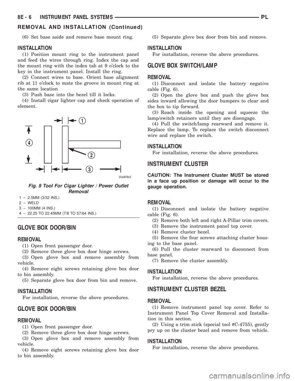
Fig. 9 Tool For Cigar Lighter / Power Outlet
Removal
1 ± 2.5MM (3/32 INS.)
2 ± WELD
3 ± 100MM (4 INS.)
4 ± 22.25 TO 22.45MM (7/8 TO 57/64 INS.)
8E - 6 INSTRUMENT PANEL SYSTEMSPL
REMOVAL AND INSTALLATION (Continued)
Page 254 of 1285
INSTRUMENT CLUSTER LAMPS
WARNINGS/INDICATORS
The instrument cluster warning/indicator lamps
are all serviceable Light Emitting Diodes (LED's).
The instrument cluster must first be removed, refer
to Instrument Cluster Removal and Installation in
this section, and then the defective LED just turns
out with needle nose pliers.
ILLUMINATION LAMPS
The high beam indicator, turn signals, and illumi-
nation bulbs are also serviceable. The instrument
cluster must first be removed, refer to Instrument
Cluster Removal and Installation in this section, and
then the defective bulb and socket turns out. The
bulb locations are printed on the back cover of the
instrument cluster.
INSTRUMENT PANEL ASSEMBLY
REMOVAL
(1) Disconnect and isolate the battery negative
cable (Fig. 6).
(2) Push seats back to their full back position.
(3) Using a trim stick (special tool #C-4755), gently
pry out on left and right A-pillar trim moldings and
remove.
(4) Remove top cover. Refer to Top Cover Removal
and Installation in this section.
(5) Gently pull up on cluster bezel and remove
from vehicle.
(6) Gently pull rearward on left lower instrument
panel cover and remove from vehicle.
CAUTION: Lock the steering wheel in the straight
ahead position. This will prevent clockspring dam-
age when the steering wheel rotates freely.
(7) Remove steering column. Refer to Group 19
Steering, Steering Column Removal and Installation.
(8) Remove left and right instrument panel end-
caps.
(9) Remove left and right cowl side panels.
(10) Remove center console. Refer to Group 23
Body, Center Console Removal and Installation.
(11) Depress the sides of the Data Link Connector
(DLC) and remove from instrument panel reinforce-
ment.
(12) Remove four bulkhead instrument panel
retaining screws.
(13) Remove two bolts on top of the brake pedal
support bracket.
(14) Remove two center support mounting bolts.
(15) Remove left and right A-pillar mounting bolts,
two on each side.(16) Disconnect right side antenna connector.
(17) Remove left and right A-pillar door harness
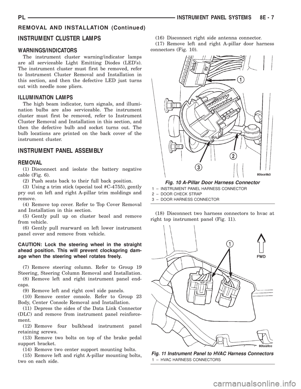
connectors (Fig. 10).
(18) Disconnect two harness connectors to hvac at
right top instrument panel (Fig. 11).
Fig. 10 A-Pillar Door Harness Connector
1 ± INSTRUMENT PANEL HARNESS CONNECTOR
2 ± DOOR CHECK STRAP
3 ± DOOR HARNESS CONNECTOR
Fig. 11 Instrument Panel to HVAC Harness Connectors
1 ± HVAC HARNESS CONNECTORS
PLINSTRUMENT PANEL SYSTEMS 8E - 7
REMOVAL AND INSTALLATION (Continued)
Page 270 of 1285
AUDIO SYSTEM
TABLE OF CONTENTS
page page
GENERAL INFORMATION
INTRODUCTION..........................1
DESCRIPTION AND OPERATION
INTERFERENCE ELIMINATION...............1
DIAGNOSIS AND TESTING
AUDIO DIAGNOSTIC TEST PROCEDURES......1
TESTING................................1
BENCH TEST FOR ANTENNA MALFUNCTION...7REMOVAL AND INSTALLATION
CD CHANGER............................7
FRONT DOOR SPEAKER....................8
INSTRUMENT PANEL SPEAKER(S)...........8
MAST and ANTENNA ASSEMBLY.............8
RADIO..................................9
REAR SHELF SPEAKER(S).................10
GENERAL INFORMATION
INTRODUCTION
Operating instructions for the factory installed
audio systems can be found in the Owner's Manual
provided with the vehicle.
The vehicles are equipped with an Interior (Igni-
tion Off Draw) fuse in the Power Distribution Center
located in the engine compartment. After the Interior
(IOD) fuse or battery has been disconnected the clock
will require resetting. The radio station presets have
a nonvolatile memory and will retain the preset sta-
tions after a battery disconnect.
The available radio options are:
²AM/FM Stereo Cassette w/Clock
²AM/FM/CD
²AM/FM Cassette w/CD Changer Controls and
Display
²CD/4 Disc Changer - In-Dash (used w/Radio CD
Changer Controls)
DESCRIPTION AND OPERATION
INTERFERENCE ELIMINATION
The radio utilizes a ground wire plugged on to a
blade terminal and is bolted to the radio chassis.
Both connector and terminal should be securely
attached. The engine has two separate ground straps
to suppress ignition noise which may interfere with
radio reception.
²Left engine mount clip on strap
²Engine to shock tower reinforcement
Inductive type spark plug cables in the high ten-
sion circuit of the ignition system complete the inter-
ference suppression. Faulty or deteriorated spark
plug wires should be replaced.
DIAGNOSIS AND TESTING
AUDIO DIAGNOSTIC TEST PROCEDURES
CAUTION: The CD player will only operate between
approximate temperatures of -23ÉC and +65ÉC (-10ÉF
and +145ÉF).
Whenever a radio malfunction occurs;
(1) First check FUSES:
(a) Power Distribution Center (PDC), Interior
lamp fuse, M1 - Radio Memory Feed
(b) Fuse Block:
(I) Fuse 12, Illumination in the fuse block
(II) Fuse 16, Ignition feed in the fuse block
NOTE: The vehicles are shipped with the INTERIOR
LAMP fuse disconnected.
(2) Verify, the radio wire harness are properly con-
nected before starting normal diagnosis and repair
procedures. Refer to Audio Diagnostic Charts and/or
Group 8W, Wiring Diagrams, Radio Section.
TESTING
The antenna has a short cable which connects into
the instrument panel harness. The connection is
made on the right side of the instrument panel.
Antenna performance may be tested by substitut-
ing a known good antenna. It is also possible to
check short or open circuits with an ohmmeter or
continuity light once the antenna cable is discon-
nected from the radio as follows:
(1) Continuity should be present between the
antenna mast and radio end pin of antenna cable
plug (Fig. 1).
(2) No continuity should be observed or a very
high resistance of several megohms between the
ground shell of the connector and radio end pin.
PLAUDIO SYSTEM 8F - 1
Page 318 of 1285
INSTALLATION
(1) Push bulb in socket and snap into place.
(2) Install floor console.
GLOVE BOX LAMP BULB
REMOVAL
(1) Open glove box door.
(2) Pull downward on lamp/switch assembly to dis-
engage tabs from instrument panel.
(3) Pull bulb from socket.
INSTALLATION
(1) Push bulb into socket.
(2) Place lamp/switch assembly into position.
(3) Push lamp/switch assembly to lock tabs.
(4) Check lamp operation, and close glove door.
FLOOR CONSOLE LAMP BULB
REMOVAL
(1) Using a flat bladed tool, slide it between the
lamp and instrument panel to disengage tabs.(2) Remove bulb from lamp socket.
INSTALLATION
(1) Install bulb into socket.
(2) Place lamp into position.
(3) Push lamp to lock tabs.
(4) Check lamp operation.
VISOR VANITY LAMP BULB
REMOVAL
(1) Lower visor.
(2) Insert a small flat bladed tool between the
lamp lens and lamp.
(3) Carefully pry lens outward.
(4) Remove bulb from socket.
INSTALLATION
(1) Position bulb in socket and snap into place.
(2) Position lens on lamp and snap into place.
PLLAMPS 8L - 11
REMOVAL AND INSTALLATION (Continued)
Page 322 of 1285
INSTALLATION
(1) Position lamp on hood and install screw.
(2) Connect lamp wire connector.
(3) Install lamp bulb.
(4) Install lens lamp.
(5) Close hood.
REAR CARGO LAMP
REMOVAL
(1) Insert a trim stick or small flat blade between
the lamp lens and rear shelf reinforcement panel.
(2) Pry the lamp lens downward.
(3) Disconnect wire connector.
(4) Remove lamp from vehicle.
INSTALLATION
(1) Place lamp into position.
(2) Connect wire connector.
(3) Install lamp lens.
DOME LAMP
REMOVAL
(1) Insert a trim stick between the dome lamp
bezel and dome lamp lens. Carefully pry down on one
side of the lamp lens.(2) Carefully pull down on lamp lens to remove
lamp from headliner.
(3) Disconnect wire connector.
(4) Remove lamp from vehicle.
INSTALLATION
(1) Place lamp into position.
(2) Connect wire connector.
(3) Install dome lamp and lens.
GLOVE BOX LAMP BULB
REMOVAL
(1) Open glove box door.
(2) Pull downward on lamp/switch assembly to dis-
engage tabs from instrument panel.
(3) Pull bulb from socket.
(4) Disconnect wire connector from lamp and
remove glove box lamp/switch.
INSTALLATION
(1) Push bulb into socket.
(2) Place lamp/switch assembly into position.
(3) Connect wire connector to the lamp/switch.
(4) Push lamp/switch assembly to lock tabs.
(5) Check lamp operation, and close glove door.
FLOOR CONSOLE LAMP BULB
REMOVAL
(1) Using a flat bladed tool, slide it between the
lamp and instrument panel to disengage tabs.
(2) Remove bulb from lamp socket.
INSTALLATION
(1) Install bulb into socket.
(2) Place lamp into position.
(3) Push lamp to lock tabs.
(4) Check lamp operation.
VISOR VANITY LAMP
The visor vanity lamp is incorporated in the visor
assembly. Replace the visor if the lamp has failed.
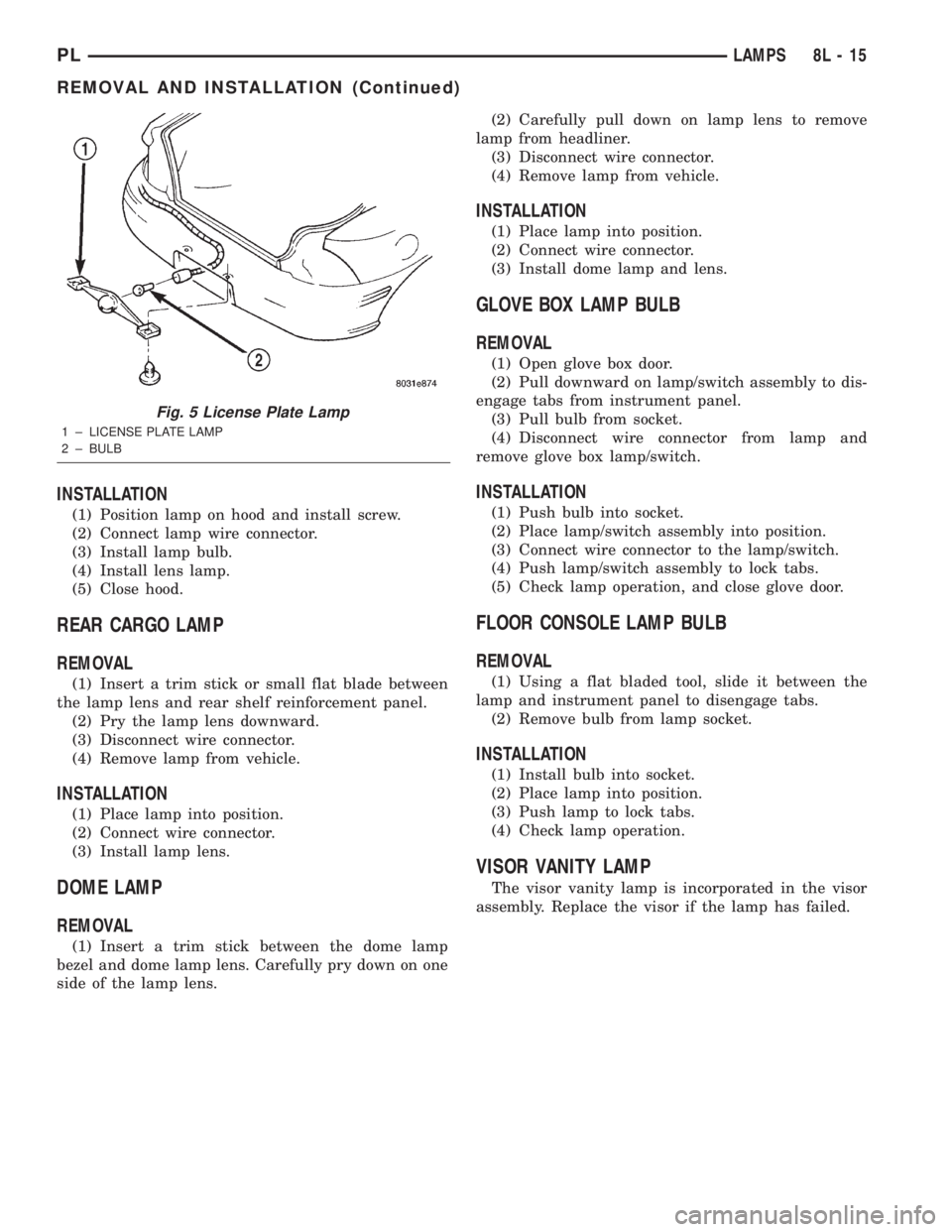
Fig. 5 License Plate Lamp
1 ± LICENSE PLATE LAMP
2 ± BULB
PLLAMPS 8L - 15
REMOVAL AND INSTALLATION (Continued)
Page 352 of 1285
PASSENGER AIRBAG MODULE
WARNING: DISCONNECT AND ISOLATE THE BAT-
TERY NEGATIVE (GROUND) CABLE BEFORE
BEGINNING ANY AIRBAG SYSTEM COMPONENT
REMOVAL OR INSTALLATION PROCEDURE. THIS
WILL DISABLE THE AIRBAG SYSTEM. FAILURE TO
DISCONNECT BATTERY COULD RESULT IN ACCI-
DENTAL AIRBAG DEPLOYMENT AND POSSIBLE
PERSONAL INJURY.
ALLOW SYSTEM CAPACITOR TO DISCHARGE
FOR 1 MINUTE BEFORE REMOVING ANY AIRBAG
COMPONENTS.
NON-DEPLOYED MODULE
REMOVAL
When removing a module for any reason other
than DEPLOYMENT.
(1) Disconnect and isolate the battery negative
cable (Fig. 4).
(2) Wait one minute for the reserve capacitor to
discharge before removing non-deployed module.
(3) Remove instrument panel top cover. Refer to
Group 8E Instrument Panel Systems, Instrument
Panel Top Cover Removal and Installation.
(4) Remove three screws to glove box door and
remove door from instrument panel.
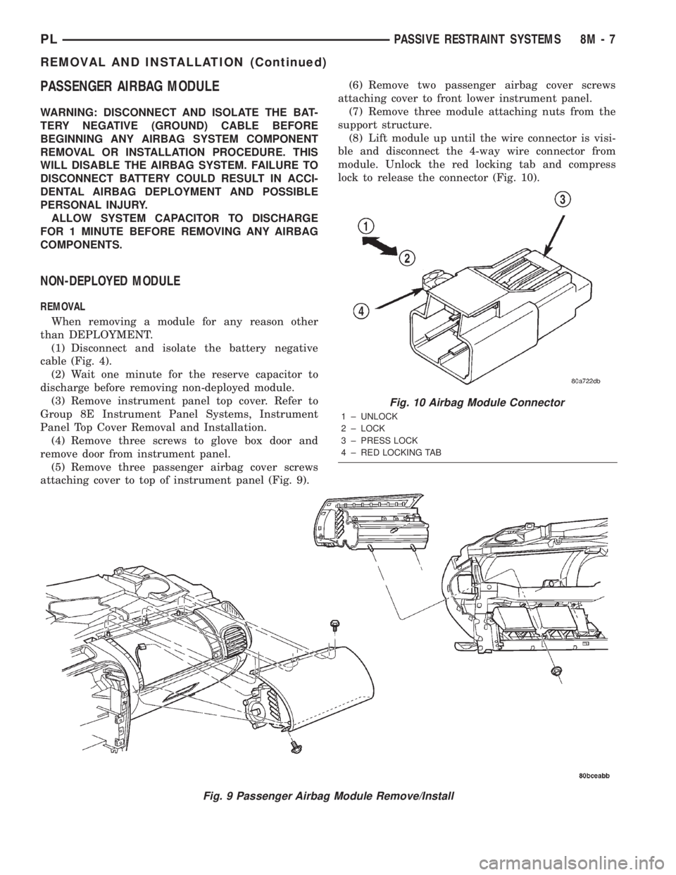
(5) Remove three passenger airbag cover screws
attaching cover to top of instrument panel (Fig. 9).(6) Remove two passenger airbag cover screws
attaching cover to front lower instrument panel.
(7) Remove three module attaching nuts from the
support structure.
(8) Lift module up until the wire connector is visi-
ble and disconnect the 4-way wire connector from
module. Unlock the red locking tab and compress
lock to release the connector (Fig. 10).
Fig. 9 Passenger Airbag Module Remove/Install
Fig. 10 Airbag Module Connector
1 ± UNLOCK
2 ± LOCK
3 ± PRESS LOCK
4 ± RED LOCKING TAB
PLPASSIVE RESTRAINT SYSTEMS 8M - 7
REMOVAL AND INSTALLATION (Continued)
Page 353 of 1285
INSTALLATION
For installation, reverse the above procedures.
Ensure that the red locking tab is in the lock position
after installing the connector. Tighten trim screws to
2 N´m (20 in. lbs.) torque. Tighten the three module
retaining nuts to 22 to 34 N´m (200 to 300 in. lbs.)
torque. Do not connect battery negative cable. Refer
to Diagnosis and Testing for Airbag System Test pro-
cedures.
DEPLOYED MODULE
REMOVAL
When removing a deployed module, rubber gloves,
eye protection, and a long-sleeved shirt should be
worn, as there may be deposits on the surface which
could irritate the skin and eyes.
(1) Roll/fold airbag towards instrument panel.
(2) Close door over folded airbag and tape door
closed.
(3) Disconnect and isolate the battery negative
cable (Fig. 4).
(4) Remove instrument panel top cover. Refer to
Group 8E Instrument Panel Systems, Instrument
Panel Top Cover Removal and Installation.
(5) Remove three screws to glove box door and
remove door from instrument panel.
(6) Remove three passenger airbag cover screws
attaching cover to top of instrument panel (Fig. 9).
(7) Remove two passenger airbag cover screws
attaching cover to front lower instrument panel.
(8) Remove three module attaching nuts from the
support structure.
(9) Lift module up until the wire connector is visi-
ble and disconnect the 4-way wire connector from
module. Unlock the red locking tab and compress
lock to release the connector (Fig. 10).
INSTALLATION
For installation, reverse the above procedures.
Ensure that the red locking tab is in the lock position
after installing the connector. Tighten trim screws to
2 N´m (20 in. lbs.) torque. Tighten the module nuts to
22 to 34 N´m (200 to 300 in. lbs.) torque. Do not con-
nect battery negative cable. Refer to Diagnosis and
Testing for Airbag System Test procedures.
STEERING WHEEL
WARNING: DISCONNECT AND ISOLATE THE BAT-
TERY NEGATIVE (GROUND) CABLE BEFORE
BEGINNING ANY AIRBAG SYSTEM COMPONENT
REMOVAL OR INSTALLATION PROCEDURE. THIS
WILL DISABLE THE AIRBAG SYSTEM. FAILURE TO
DISCONNECT BATTERY COULD RESULT IN ACCI-DENTAL AIRBAG DEPLOYMENT AND POSSIBLE
PERSONAL INJURY.
ALLOW SYSTEM CAPACITOR TO DISCHARGE
FOR 1 MINUTE BEFORE REMOVING ANY AIRBAG
COMPONENTS.
REMOVAL
(1) Adjust the steering wheel so that the tires are
in the straight ahead position. Then:
(a) Rotate the steering wheel half turn (180
degrees) to the right (clockwise).
(b) Lock column with the ignition cylinder lock.
(2) Disconnect and isolate the battery negative
cable (Fig. 4).
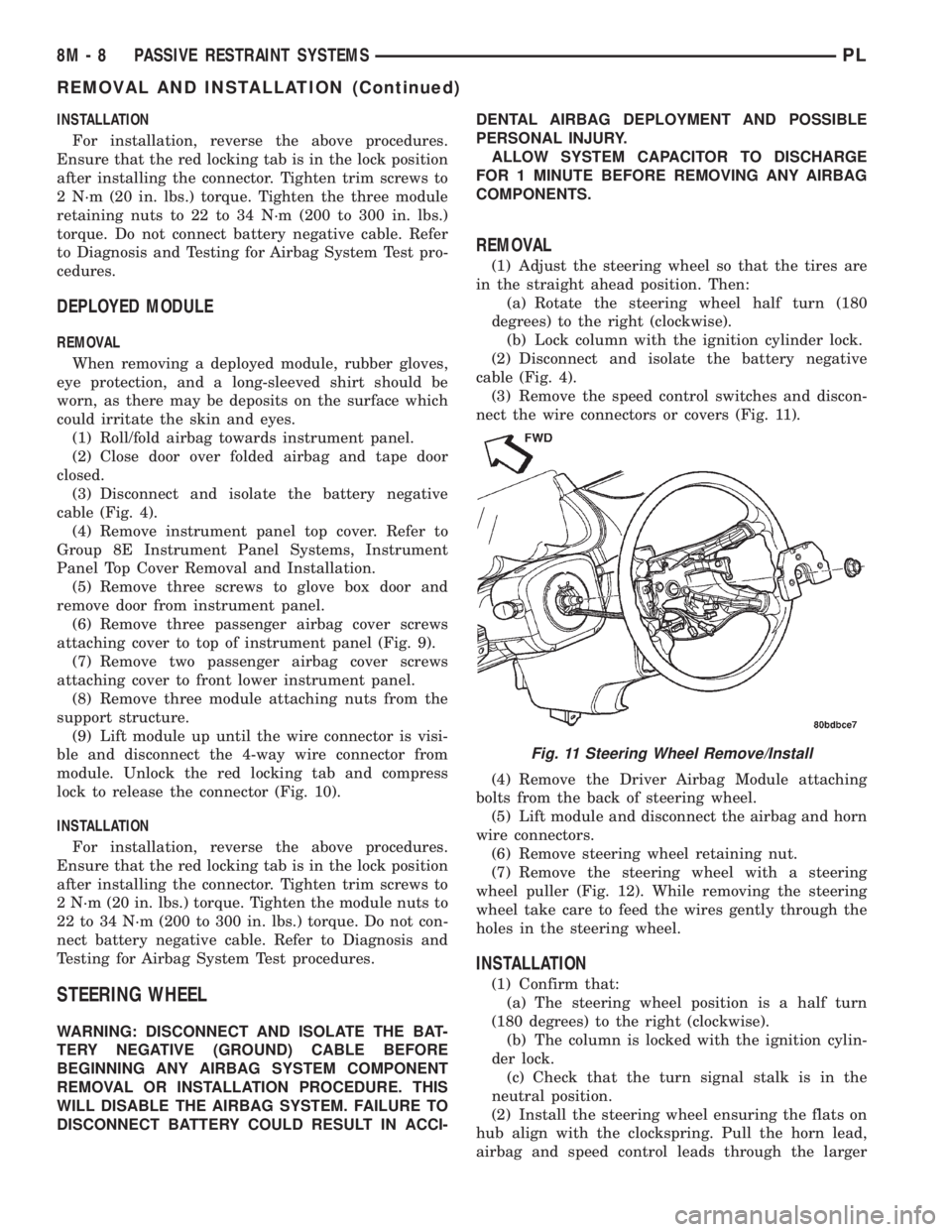
(3) Remove the speed control switches and discon-
nect the wire connectors or covers (Fig. 11).
(4) Remove the Driver Airbag Module attaching
bolts from the back of steering wheel.
(5) Lift module and disconnect the airbag and horn
wire connectors.
(6) Remove steering wheel retaining nut.
(7) Remove the steering wheel with a steering
wheel puller (Fig. 12). While removing the steering
wheel take care to feed the wires gently through the
holes in the steering wheel.
INSTALLATION
(1) Confirm that:
(a) The steering wheel position is a half turn
(180 degrees) to the right (clockwise).
(b) The column is locked with the ignition cylin-
der lock.
(c) Check that the turn signal stalk is in the
neutral position.
(2) Install the steering wheel ensuring the flats on
hub align with the clockspring. Pull the horn lead,
airbag and speed control leads through the larger
Fig. 11 Steering Wheel Remove/Install
8M - 8 PASSIVE RESTRAINT SYSTEMSPL
REMOVAL AND INSTALLATION (Continued)
Page 364 of 1285
POWER LOCK SYSTEMS
TABLE OF CONTENTS
page page
POWER DOOR LOCKS...................... 1REMOTE KEYLESS ENTRY (RKE).............. 4
POWER DOOR LOCKS
TABLE OF CONTENTS
page page
DESCRIPTION AND OPERATION
INTRODUCTION..........................1
POWER DOOR LOCKS.....................2
CHILD PROTECTION LOCKS................2
DOOR LOCK INHIBIT.......................2
DIAGNOSIS AND TESTING
DOOR LOCK MOTOR......................2
DOOR LOCK SWITCH......................2SERVICE PROCEDURES
DOUBLE ACTIVATION UNLOCK...............3
ROLLING DOOR LOCKS....................3
REMOVAL AND INSTALLATION
DOOR LOCK MOTOR/LATCH.................3
DOOR LOCK SWITCH......................3
REMOTE KEYLESS ENTRY (RKE) MODULE.....3
DESCRIPTION AND OPERATION
INTRODUCTION
All doors can be locked or unlocked electrically by
operating the switch on either front door panel.
When the door lock switch is activated the Remote
Keyless Entry Module provides power to the door
lock motors through relays internal to the module.
The Remote Keyless Entry (RKE) Module also con-
trols the Vehicle Theft Security System (VTSS).
All doors can be locked or unlocked mechanically
and independently with their respective locking
knobs. The front doors can also be unlocked by actu-
ation of the inside remote door handle.
The RKE Module has three modes of operation
including customer usage mode, dealer lot storage
mode, and shipping mode. The customer usage mode
provides full functionality of the module and is the
mode in which the RKE module should be operating
when used by the customer. Dealer lot storage mode
and shipping modes are reduced power modes meant
to extend vehicle battery life during shipping and
storage in the dealer lot. Dealer lot storage mode pro-
vides limited VTSS and power door lock functions,
but disables the Remote Keyless Entry (RKE) func-
tions. This mode is intended to be used when the
vehicle is on the dealer lot to provide VTSS coverageof the vehicle while minimizing battery drain. Ship-
ping mode disables all normal functions (i.e. power
door locks, RKE, and VTSS) of the module, and is
intended to be used when the vehicle is shipped from
the assembly plant.
NOTE: The dealer must remove the module from
ªShip Modeº and place the RKE Module into either
the ªDealer Lotº storage or ªCustomer Usageº
modes of operation after receiving the vehicle from
the assembly plant. Refer to Group 8Q-Vehicle
Theft/Security Systems, Switching Operating
Modes/Configuring a New Module under Service
Procedures.
CENTRAL LOCKING/UNLOCKING
The door locks can be locked or unlocked electri-
cally via the exterior door key cylinders to provide
the central locking/unlocking feature. The central
locking/unlocking feature incorporates a customer
programmable ``Double activation unlockº feature
which operates in the following manner: When
enabled, the first turn of the key cylinder to the
UNLOCK position (toward the front of the vehicle)
will mechanically unlock the door whose key cylinder
is being turned. A second turn of the key cylinder to
the UNLOCK position (within five seconds of the
PLPOWER LOCK SYSTEMS 8P - 1