service reset DODGE NEON 2000 Service Repair Manual
[x] Cancel search | Manufacturer: DODGE, Model Year: 2000, Model line: NEON, Model: DODGE NEON 2000Pages: 1285, PDF Size: 29.42 MB
Page 154 of 1285
ABS ELECTRONIC DIAGNOSIS
The following information is presented to give the
technician a general background on the diagnostic
capabilities of the ABS system. Complete electronic
diagnosis of the ABS system used on this vehicle is
covered in the Chassis Diagnostic Procedures manual.
Electronic diagnosis of the ABS system used on
this vehicle is performed using the DRBIIItscan
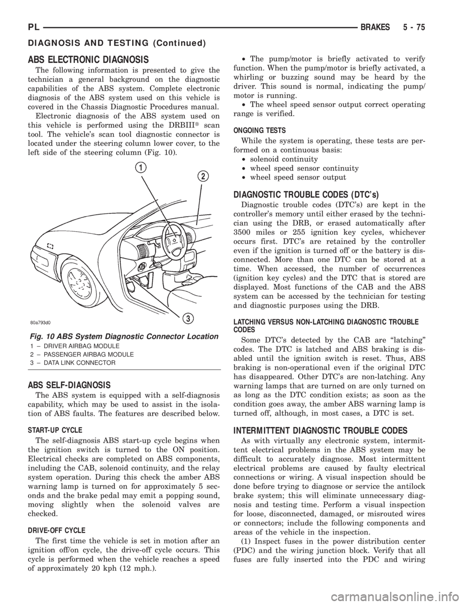
tool. The vehicle's scan tool diagnostic connector is
located under the steering column lower cover, to the
left side of the steering column (Fig. 10).
ABS SELF-DIAGNOSIS
The ABS system is equipped with a self-diagnosis
capability, which may be used to assist in the isola-
tion of ABS faults. The features are described below.
START-UP CYCLE
The self-diagnosis ABS start-up cycle begins when
the ignition switch is turned to the ON position.
Electrical checks are completed on ABS components,
including the CAB, solenoid continuity, and the relay
system operation. During this check the amber ABS
warning lamp is turned on for approximately 5 sec-
onds and the brake pedal may emit a popping sound,
moving slightly when the solenoid valves are
checked.
DRIVE-OFF CYCLE
The first time the vehicle is set in motion after an
ignition off/on cycle, the drive-off cycle occurs. This
cycle is performed when the vehicle reaches a speed
of approximately 20 kph (12 mph.).²The pump/motor is briefly activated to verify
function. When the pump/motor is briefly activated, a
whirling or buzzing sound may be heard by the
driver. This sound is normal, indicating the pump/
motor is running.
²The wheel speed sensor output correct operating
range is verified.
ONGOING TESTS
While the system is operating, these tests are per-
formed on a continuous basis:
²solenoid continuity
²wheel speed sensor continuity
²wheel speed sensor output
DIAGNOSTIC TROUBLE CODES (DTC's)
Diagnostic trouble codes (DTC's) are kept in the
controller's memory until either erased by the techni-
cian using the DRB, or erased automatically after
3500 miles or 255 ignition key cycles, whichever
occurs first. DTC's are retained by the controller
even if the ignition is turned off or the battery is dis-
connected. More than one DTC can be stored at a
time. When accessed, the number of occurrences
(ignition key cycles) and the DTC that is stored are
displayed. Most functions of the CAB and the ABS
system can be accessed by the technician for testing
and diagnostic purposes using the DRB.
LATCHING VERSUS NON-LATCHING DIAGNOSTIC TROUBLE
CODES
Some DTC's detected by the CAB are ªlatchingº
codes. The DTC is latched and ABS braking is dis-
abled until the ignition switch is reset. Thus, ABS
braking is non-operational even if the original DTC
has disappeared. Other DTC's are non-latching. Any
warning lamps that are turned on are only turned on
as long as the DTC condition exists; as soon as the
condition goes away, the amber ABS warning lamp is
turned off, although, in most cases, a DTC is set.
INTERMITTENT DIAGNOSTIC TROUBLE CODES
As with virtually any electronic system, intermit-
tent electrical problems in the ABS system may be
difficult to accurately diagnose. Most intermittent
electrical problems are caused by faulty electrical
connections or wiring. A visual inspection should be
done before trying to diagnose or service the antilock
brake system; this will eliminate unnecessary diag-
nosis and testing time. Perform a visual inspection
for loose, disconnected, damaged, or misrouted wires
or connectors; include the following components and
areas of the vehicle in the inspection.
(1) Inspect fuses in the power distribution center
(PDC) and the wiring junction block. Verify that all
fuses are fully inserted into the PDC and wiring
Fig. 10 ABS System Diagnostic Connector Location
1 ± DRIVER AIRBAG MODULE
2 ± PASSENGER AIRBAG MODULE
3 ± DATA LINK CONNECTOR
PLBRAKES 5 - 75
DIAGNOSIS AND TESTING (Continued)
Page 166 of 1285
CLUTCH
TABLE OF CONTENTS
page page
DESCRIPTION AND OPERATION
MODULAR CLUTCH ASSEMBLY..............1
CLUTCH CABLE..........................1
CLUTCH INTERLOCK/UPSTOP SWITCH........1
DIAGNOSIS AND TESTING
CLUTCH SYSTEM DIAGNOSIS...............2
DRIVE PLATE MISALIGNMENT..............5
CLUTCH CHATTER COMPLAINTS............5
CLASH±INTO±REVERSE COMPLAINTS........5
CLUTCH INTERLOCK/UPSTOP SWITCH........5REMOVAL AND INSTALLATION
CLUTCH CABLE..........................7
CLUTCH INTERLOCK/UPSTOP SWITCH........8
MODULAR CLUTCH ASSEMBLY..............8
RELEASE BEARING AND FORK.............12
CLEANING AND INSPECTION
CLUTCH CONTAMINATION.................12
CLEANING PRECAUTIONS.................13
SPECIFICATIONS
TORQUE...............................13
DESCRIPTION AND OPERATION
MODULAR CLUTCH ASSEMBLY
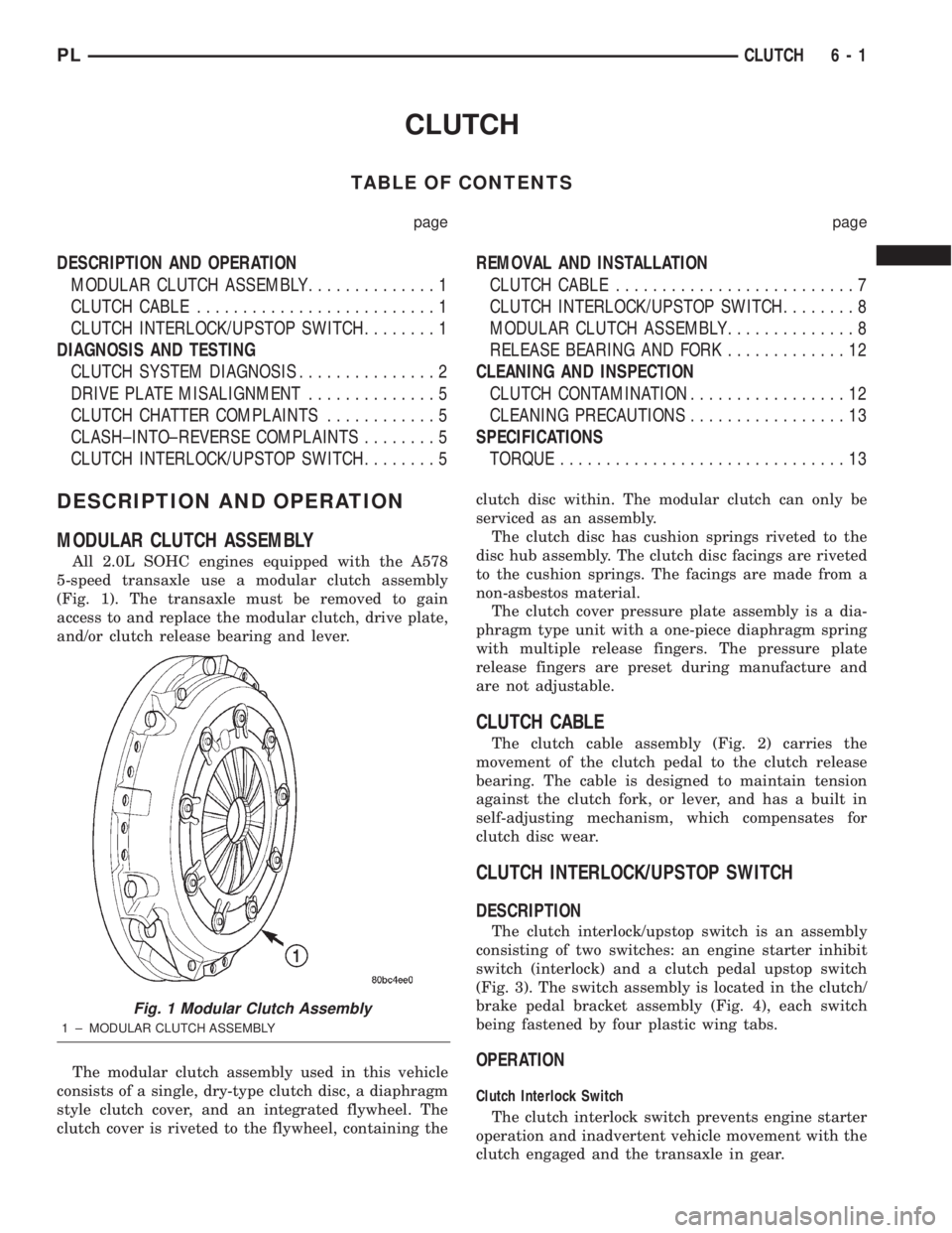
All 2.0L SOHC engines equipped with the A578
5-speed transaxle use a modular clutch assembly
(Fig. 1). The transaxle must be removed to gain
access to and replace the modular clutch, drive plate,
and/or clutch release bearing and lever.
The modular clutch assembly used in this vehicle
consists of a single, dry-type clutch disc, a diaphragm
style clutch cover, and an integrated flywheel. The
clutch cover is riveted to the flywheel, containing theclutch disc within. The modular clutch can only be
serviced as an assembly.
The clutch disc has cushion springs riveted to the
disc hub assembly. The clutch disc facings are riveted
to the cushion springs. The facings are made from a
non-asbestos material.
The clutch cover pressure plate assembly is a dia-
phragm type unit with a one-piece diaphragm spring
with multiple release fingers. The pressure plate
release fingers are preset during manufacture and
are not adjustable.
CLUTCH CABLE
The clutch cable assembly (Fig. 2) carries the
movement of the clutch pedal to the clutch release
bearing. The cable is designed to maintain tension
against the clutch fork, or lever, and has a built in
self-adjusting mechanism, which compensates for
clutch disc wear.
CLUTCH INTERLOCK/UPSTOP SWITCH
DESCRIPTION
The clutch interlock/upstop switch is an assembly
consisting of two switches: an engine starter inhibit
switch (interlock) and a clutch pedal upstop switch
(Fig. 3). The switch assembly is located in the clutch/
brake pedal bracket assembly (Fig. 4), each switch
being fastened by four plastic wing tabs.
OPERATION
Clutch Interlock Switch
The clutch interlock switch prevents engine starter
operation and inadvertent vehicle movement with the
clutch engaged and the transaxle in gear.
Fig. 1 Modular Clutch Assembly
1 ± MODULAR CLUTCH ASSEMBLY
PLCLUTCH 6 - 1
Page 249 of 1285
DESCRIPTION AND OPERATION
HEADLAMP SWITCH
The headlamp switch is part of the Multi-Function
Switch. Refer to Group 8J, Turn Signal and Flasher
for the Multi-Function Switch Test, Removal and
Installation procedures.
INSTRUMENT CLUSTER
There are two conventional instrument cluster
assemblies available. The clusters electronically drive
the speedometer, odometer, gauges, and tachometer
(if equipped). Refer to (Fig. 2) and (Fig. 3).
The instrument cluster controls the courtesy
lamps, it receives and sends messages to other mod-
ules via the PCI bus circuit, it controls all the instru-
ment illumination and the chime is also an integral
part of the cluster. The front turn signals are wired
through the cluster and then go to the front lamps.
The reason being that the DRL module is built into
the cluster (if equipped).
All gauges in the electronic clusters are the analog
type gauges. When the ignition switch is moved to
the OFF position, the cluster drives each gauge to its
lowest position. The individual gauges are not servi-
cable and require complete replacement of the cluster
if one or more gauges are inoperable.
One button is used to switch the display from trip
to total mileage. Holding the button when the display
is in the trip mode will reset the trip mileage. This
button is also used to put the cluster in self-diagnos-
tic mode. Refer to Service Procedures, Cluster Self-
Diagnostics in this section. Most of the indicators will
come on briefly for a bulb heck when the ignition is
turned from OFF to ON. All of the LED's are replace-
able.
In the event that the instrument cluster looses
communication with all other modules on the PCI
bus, the cluster will display ªnobusº in the VF dis-
play. The VF display also displays ªDoorº, ªCruiseº,
ªTracº, and odometer trip or total.
If the cluster does not detect voltage on the cour-
tesy lamp circuit, the message ªFUSEº will alternate
with the odometer/trip odometer for 30 seconds after
the ignition is turned on and for 15 seconds after the
vehicle is first moved. The lack of voltage can be due
to the M1 Fused B(+) (IOD) fuse being open, a bad or
missing courtesy lamp bulb, or a circuit problem.
WARNING AND INDICATOR LAMPS
The instrument cluster has warning lamps and
indicators for the following systems:
²Airbag
²Anti-lock Brakes (ABS) if equipped
²Brake warning
²Charging System²Front fog lamps (if equipped)
²High beam indicator
²Low fuel (premium cluster only)
²Low oil pressure
²Malfunction indicator (service engine soon) lamp
²Right and left turn signals
²Seat belt warning
²Security system
²Trac-Off (ABS equipped vehicles only)
The instrument cluster has a Vacuum Fluorescent
(VF) display for the following systems:
²Cruise
²Door (ajar)
²Odometer
²Set (cruise)
²Trac
²Trip
DIAGNOSIS AND TESTING
AIRBAG WARNING SYSTEM
For testing of this system refer to Group 8M, Pas-
sive Restraint Systems.
BRAKE SYSTEM WARNING LAMP TEST
The brake warning lamp illuminates when the
parking brake is applied with ignition switch turned
to the ON position. The same lamp will also illumi-
nate if one of the two service brake systems fail the
when brake pedal is applied.
To test the system:
²As the ignition switch is turned to the start posi-
tion the lamp should light.
²Turn ignition switch to the ON position and
apply the parking brake. The lamp should light.
If lamp fails to light inspect for:
²A burned out lamp
²Loose, corroded or damaged socket
²A damaged circuit board
²A broken or disconnected wire at the switch
²Defective switch
To test the service brake warning system, refer to
Group 5, Brakes, Hydraulic System Control Valves.
INSTRUMENT CLUSTER LAMPS
Every time the vehicle is switched to the START/
RUN position, the cluster goes through a BULB
CHECK. This tests most of the indicator lamps and
Vacuum Fluorescent (VF) displays. If only one lamp
is out, remove the instrument cluster and replace the
defective bulb or Light Emitting Diode (LED). If
some or all of the lamps fail to light, refer to the
proper Body Diagnostics Procedures Manual.
8E - 2 INSTRUMENT PANEL SYSTEMSPL
Page 251 of 1285
MULTIPLE/INDIVIDUAL GAUGES INOPERATIVE
Test speedometer, tachometer and other gauges for
malfunction:
(1) Remove the cluster. Refer to Cluster Removal
and Installation.
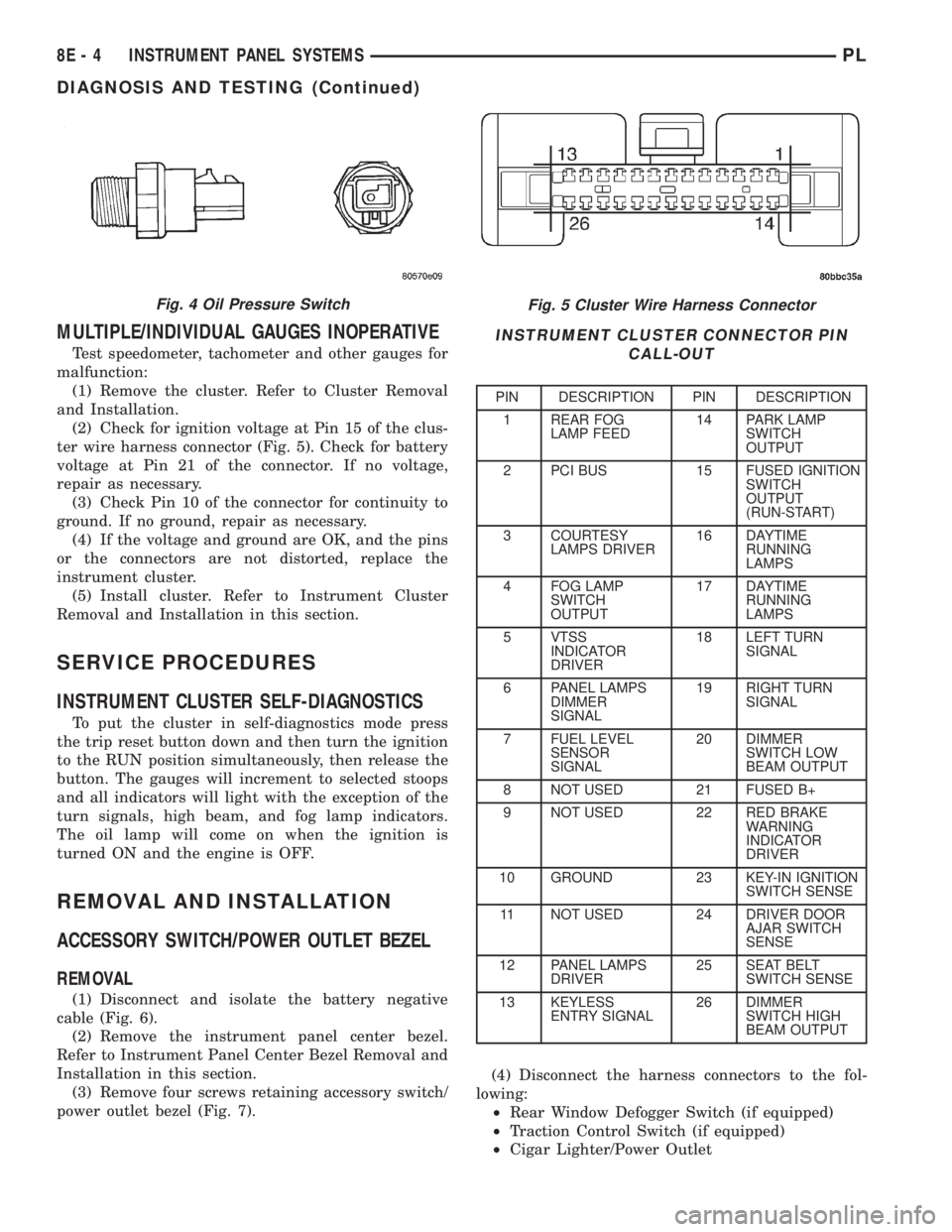
(2) Check for ignition voltage at Pin 15 of the clus-
ter wire harness connector (Fig. 5). Check for battery
voltage at Pin 21 of the connector. If no voltage,
repair as necessary.
(3) Check Pin 10 of the connector for continuity to
ground. If no ground, repair as necessary.
(4) If the voltage and ground are OK, and the pins
or the connectors are not distorted, replace the
instrument cluster.
(5) Install cluster. Refer to Instrument Cluster
Removal and Installation in this section.
SERVICE PROCEDURES
INSTRUMENT CLUSTER SELF-DIAGNOSTICS
To put the cluster in self-diagnostics mode press
the trip reset button down and then turn the ignition
to the RUN position simultaneously, then release the
button. The gauges will increment to selected stoops
and all indicators will light with the exception of the
turn signals, high beam, and fog lamp indicators.
The oil lamp will come on when the ignition is
turned ON and the engine is OFF.
REMOVAL AND INSTALLATION
ACCESSORY SWITCH/POWER OUTLET BEZEL
REMOVAL
(1) Disconnect and isolate the battery negative
cable (Fig. 6).
(2) Remove the instrument panel center bezel.
Refer to Instrument Panel Center Bezel Removal and
Installation in this section.
(3) Remove four screws retaining accessory switch/
power outlet bezel (Fig. 7).(4) Disconnect the harness connectors to the fol-
lowing:
²Rear Window Defogger Switch (if equipped)
²Traction Control Switch (if equipped)
²Cigar Lighter/Power Outlet
Fig. 5 Cluster Wire Harness Connector
INSTRUMENT CLUSTER CONNECTOR PIN
CALL-OUT
PIN DESCRIPTION PIN DESCRIPTION
1 REAR FOG
LAMP FEED14 PARK LAMP
SWITCH
OUTPUT
2 PCI BUS 15 FUSED IGNITION
SWITCH
OUTPUT
(RUN-START)
3 COURTESY
LAMPS DRIVER16 DAYTIME
RUNNING
LAMPS
4 FOG LAMP
SWITCH
OUTPUT17 DAYTIME
RUNNING
LAMPS
5 VTSS
INDICATOR
DRIVER18 LEFT TURN
SIGNAL
6 PANEL LAMPS
DIMMER
SIGNAL19 RIGHT TURN
SIGNAL
7 FUEL LEVEL
SENSOR
SIGNAL20 DIMMER
SWITCH LOW
BEAM OUTPUT
8 NOT USED 21 FUSED B+
9 NOT USED 22 RED BRAKE
WARNING
INDICATOR
DRIVER
10 GROUND 23 KEY-IN IGNITION
SWITCH SENSE
11 NOT USED 24 DRIVER DOOR
AJAR SWITCH
SENSE
12 PANEL LAMPS
DRIVER25 SEAT BELT
SWITCH SENSE
13 KEYLESS
ENTRY SIGNAL26 DIMMER
SWITCH HIGH
BEAM OUTPUT
Fig. 4 Oil Pressure Switch
8E - 4 INSTRUMENT PANEL SYSTEMSPL
DIAGNOSIS AND TESTING (Continued)
Page 360 of 1285
POWER DISTRIBUTION SYSTEMS
TABLE OF CONTENTS
page page
DESCRIPTION AND OPERATION
POWER DISTRIBUTION SYSTEM.............1
POWER DISTRIBUTION CENTER (PDC).......1
FUSE BLOCK.............................2REMOVAL AND INSTALLATION
FUSE BLOCK.............................2
POWER DISTRIBUTION CENTER (PDC).......2
DESCRIPTION AND OPERATION
POWER DISTRIBUTION SYSTEM
This group covers the various standard and
optional power distribution components used on this
model. Refer to the Component Index of Group 8W -
Wiring Diagrams for complete circuit diagrams of the
various power distribution components.
The power distribution system for this vehicle is
designed to provide safe, reliable, centralized and
convenient to access distribution of the electrical cur-
rent required to operate all of the many standard
and optional factory-installed electrical and electronic
powertrain, chassis, safety, comfort and convenience
systems. At the same time, these systems were
designed to provide centralized locations for conduct-
ing diagnosis of faulty circuits, and for sourcing the
additional current requirements of many aftermarket
vehicle accessory and convenience items.
These power distribution systems also incorporate
various types of circuit control and protection fea-
tures, including:
²Fuses
²Fuse cartridges
²Fusible links
²Automatic resetting circuit breakers
²Relays
²Flashers
²Timers
²Circuit splice blocks.
The power distribution system for this vehicle con-
sists of the following components:
²Power Distribution Center (PDC)
²Fuse Block
Following are general descriptions of the major
components in the power distribution system. Refer
to the owner's manual in the vehicle glove box for
more information on the features, use and operation
of all of the power distribution system components.
POWER DISTRIBUTION CENTER (PDC)
All of the electrical current distributed throughout
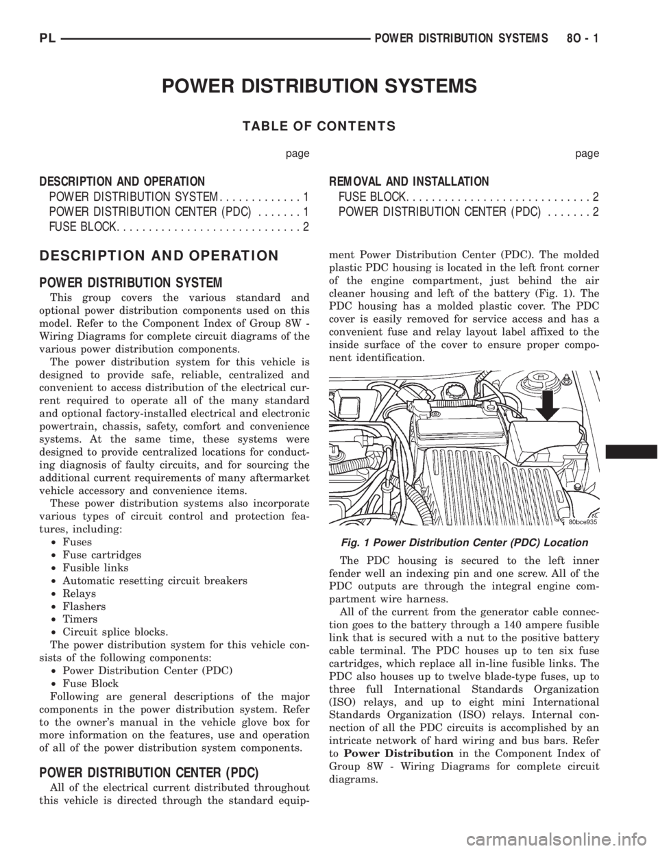
this vehicle is directed through the standard equip-ment Power Distribution Center (PDC). The molded
plastic PDC housing is located in the left front corner
of the engine compartment, just behind the air
cleaner housing and left of the battery (Fig. 1). The
PDC housing has a molded plastic cover. The PDC
cover is easily removed for service access and has a
convenient fuse and relay layout label affixed to the
inside surface of the cover to ensure proper compo-
nent identification.
The PDC housing is secured to the left inner
fender well an indexing pin and one screw. All of the
PDC outputs are through the integral engine com-
partment wire harness.
All of the current from the generator cable connec-
tion goes to the battery through a 140 ampere fusible
link that is secured with a nut to the positive battery
cable terminal. The PDC houses up to ten six fuse
cartridges, which replace all in-line fusible links. The
PDC also houses up to twelve blade-type fuses, up to
three full International Standards Organization
(ISO) relays, and up to eight mini International
Standards Organization (ISO) relays. Internal con-
nection of all the PDC circuits is accomplished by an
intricate network of hard wiring and bus bars. Refer
toPower Distributionin the Component Index of
Group 8W - Wiring Diagrams for complete circuit
diagrams.
Fig. 1 Power Distribution Center (PDC) Location
PLPOWER DISTRIBUTION SYSTEMS 8O - 1
Page 361 of 1285
The fusible link, fuses and relays are available for
service replacement. The PDC unit cannot be
repaired and is only serviced as a unit with the
engine compartment wire harness. If the PDC is
faulty or damaged, the engine compartment wire har-
ness assembly must be replaced.
FUSE BLOCK
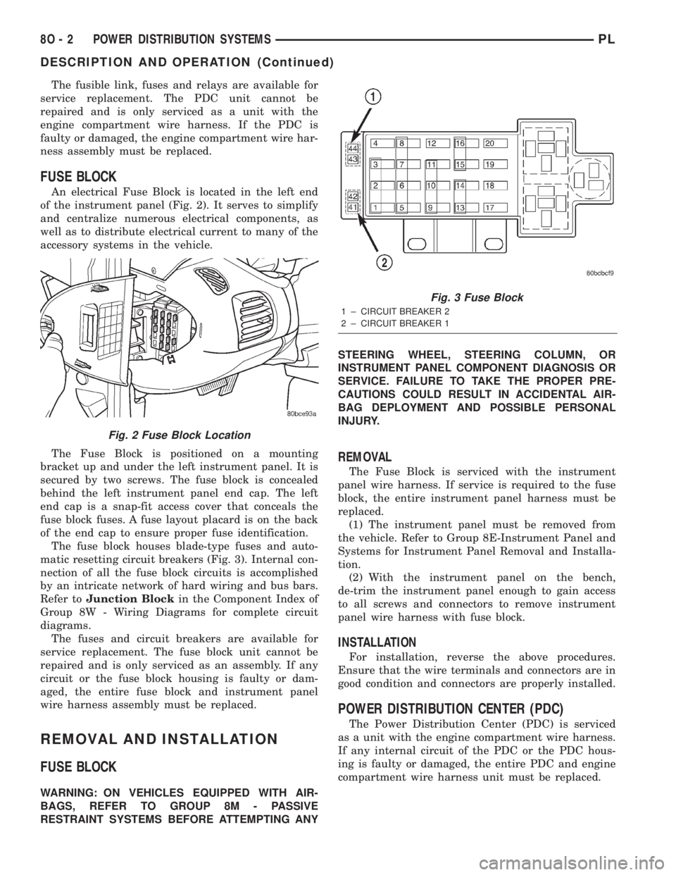
An electrical Fuse Block is located in the left end
of the instrument panel (Fig. 2). It serves to simplify
and centralize numerous electrical components, as
well as to distribute electrical current to many of the
accessory systems in the vehicle.
The Fuse Block is positioned on a mounting
bracket up and under the left instrument panel. It is
secured by two screws. The fuse block is concealed
behind the left instrument panel end cap. The left
end cap is a snap-fit access cover that conceals the
fuse block fuses. A fuse layout placard is on the back
of the end cap to ensure proper fuse identification.
The fuse block houses blade-type fuses and auto-
matic resetting circuit breakers (Fig. 3). Internal con-
nection of all the fuse block circuits is accomplished
by an intricate network of hard wiring and bus bars.
Refer toJunction Blockin the Component Index of
Group 8W - Wiring Diagrams for complete circuit
diagrams.
The fuses and circuit breakers are available for
service replacement. The fuse block unit cannot be
repaired and is only serviced as an assembly. If any
circuit or the fuse block housing is faulty or dam-
aged, the entire fuse block and instrument panel
wire harness assembly must be replaced.
REMOVAL AND INSTALLATION
FUSE BLOCK
WARNING: ON VEHICLES EQUIPPED WITH AIR-
BAGS, REFER TO GROUP 8M - PASSIVE
RESTRAINT SYSTEMS BEFORE ATTEMPTING ANYSTEERING WHEEL, STEERING COLUMN, OR
INSTRUMENT PANEL COMPONENT DIAGNOSIS OR
SERVICE. FAILURE TO TAKE THE PROPER PRE-
CAUTIONS COULD RESULT IN ACCIDENTAL AIR-
BAG DEPLOYMENT AND POSSIBLE PERSONAL
INJURY.
REMOVAL
The Fuse Block is serviced with the instrument
panel wire harness. If service is required to the fuse
block, the entire instrument panel harness must be
replaced.
(1) The instrument panel must be removed from
the vehicle. Refer to Group 8E-Instrument Panel and
Systems for Instrument Panel Removal and Installa-
tion.
(2) With the instrument panel on the bench,
de-trim the instrument panel enough to gain access
to all screws and connectors to remove instrument
panel wire harness with fuse block.
INSTALLATION
For installation, reverse the above procedures.
Ensure that the wire terminals and connectors are in
good condition and connectors are properly installed.
POWER DISTRIBUTION CENTER (PDC)
The Power Distribution Center (PDC) is serviced
as a unit with the engine compartment wire harness.
If any internal circuit of the PDC or the PDC hous-
ing is faulty or damaged, the entire PDC and engine
compartment wire harness unit must be replaced.
Fig. 2 Fuse Block Location
Fig. 3 Fuse Block
1 ± CIRCUIT BREAKER 2
2 ± CIRCUIT BREAKER 1
8O - 2 POWER DISTRIBUTION SYSTEMSPL
DESCRIPTION AND OPERATION (Continued)
Page 406 of 1285
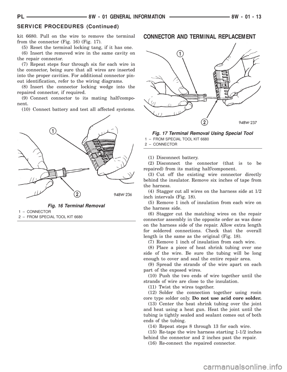
kit 6680. Pull on the wire to remove the terminal
from the connector (Fig. 16) (Fig. 17).
(5) Reset the terminal locking tang, if it has one.
(6) Insert the removed wire in the same cavity on
the repair connector.
(7) Repeat steps four through six for each wire in
the connector, being sure that all wires are inserted
into the proper cavities. For additional connector pin-
out identification, refer to the wiring diagrams.
(8) Insert the connector locking wedge into the
repaired connector, if required.
(9) Connect connector to its mating half/compo-
nent.
(10) Connect battery and test all affected systems.CONNECTOR AND TERMINAL REPLACEMENT
(1) Disconnect battery.
(2) Disconnect the connector (that is to be
repaired) from its mating half/component.
(3) Cut off the existing wire connector directly
behind the insulator. Remove six inches of tape from
the harness.
(4) Stagger cut all wires on the harness side at 1/2
inch intervals (Fig. 18).
(5) Remove 1 inch of insulation from each wire on
the harness side.
(6) Stagger cut the matching wires on the repair
connector assembly in the opposite order as was done
on the harness side of the repair. Allow extra length
for soldered connections. Check that the overall
length is the same as the original (Fig. 18).
(7) Remove 1 inch of insulation from each wire.
(8) Place a piece of heat shrink tubing over one
side of the wire. Be sure the tubing will be long
enough to cover and seal the entire repair area.
(9) Spread the strands of the wire apart on each
part of the exposed wires.
(10) Push the two ends of wire together until the
strands of wire are close to the insulation.
(11) Twist the wires together.
(12) Solder the connection together using rosin
core type solder only.Do not use acid core solder.
(13) Center the heat shrink tubing over the joint
and heat using a heat gun. Heat the joint until the
tubing is tightly sealed and sealant comes out of both
ends of the tubing.
(14) Repeat steps 8 through 13 for each wire.
(15) Re-tape the wire harness starting 1-1/2 inches
behind the connector and 2 inches past the repair.
(16) Re-connect the repaired connector.
Fig. 16 Terminal Removal
1 ± CONNECTOR
2 ± FROM SPECIAL TOOL KIT 6680
Fig. 17 Terminal Removal Using Special Tool
1 ± FROM SPECIAL TOOL KIT 6680
2 ± CONNECTOR
PL8W - 01 GENERAL INFORMATION 8W - 01 - 13
SERVICE PROCEDURES (Continued)
Page 877 of 1285
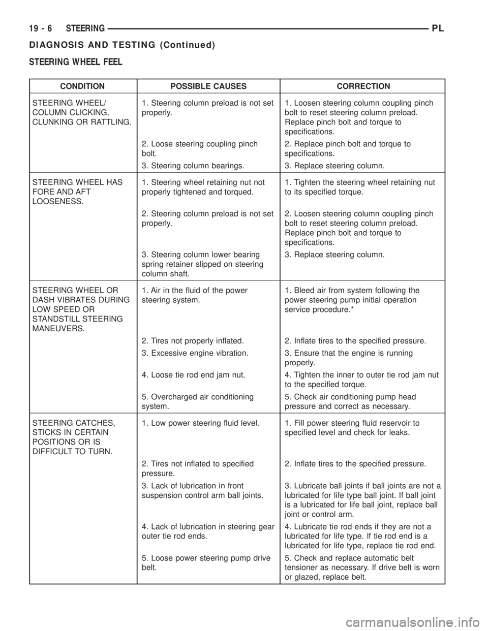
STEERING WHEEL FEEL
CONDITION POSSIBLE CAUSES CORRECTION
STEERING WHEEL/
COLUMN CLICKING,
CLUNKING OR RATTLING.1. Steering column preload is not set
properly.1. Loosen steering column coupling pinch
bolt to reset steering column preload.
Replace pinch bolt and torque to
specifications.
2. Loose steering coupling pinch
bolt.2. Replace pinch bolt and torque to
specifications.
3. Steering column bearings. 3. Replace steering column.
STEERING WHEEL HAS
FORE AND AFT
LOOSENESS.1. Steering wheel retaining nut not
properly tightened and torqued.1. Tighten the steering wheel retaining nut
to its specified torque.
2. Steering column preload is not set
properly.2. Loosen steering column coupling pinch
bolt to reset steering column preload.
Replace pinch bolt and torque to
specifications.
3. Steering column lower bearing
spring retainer slipped on steering
column shaft.3. Replace steering column.
STEERING WHEEL OR
DASH VIBRATES DURING
LOW SPEED OR
STANDSTILL STEERING
MANEUVERS.1. Air in the fluid of the power
steering system.1. Bleed air from system following the
power steering pump initial operation
service procedure.*
2. Tires not properly inflated. 2. Inflate tires to the specified pressure.
3. Excessive engine vibration. 3. Ensure that the engine is running
properly.
4. Loose tie rod end jam nut. 4. Tighten the inner to outer tie rod jam nut
to the specified torque.
5. Overcharged air conditioning
system.5. Check air conditioning pump head
pressure and correct as necessary.
STEERING CATCHES,
STICKS IN CERTAIN
POSITIONS OR IS
DIFFICULT TO TURN.1. Low power steering fluid level. 1. Fill power steering fluid reservoir to
specified level and check for leaks.
2. Tires not inflated to specified
pressure.2. Inflate tires to the specified pressure.
3. Lack of lubrication in front
suspension control arm ball joints.3. Lubricate ball joints if ball joints are not a
lubricated for life type ball joint. If ball joint
is a lubricated for life ball joint, replace ball
joint or control arm.
4. Lack of lubrication in steering gear
outer tie rod ends.4. Lubricate tie rod ends if they are not a
lubricated for life type. If tie rod end is a
lubricated for life type, replace tie rod end.
5. Loose power steering pump drive
belt.5. Check and replace automatic belt
tensioner as necessary. If drive belt is worn
or glazed, replace belt.
19 - 6 STEERINGPL
DIAGNOSIS AND TESTING (Continued)
Page 909 of 1285
(25) Turn the key to OFF and remove the scan tool
from the vehicle.
(26) Test the operation of the horn, wipers and any
other functions that are steering column operated. If
applicable, reset the radio and the clock.
(27) If the steering column is a tilt column, verify
the tilt mechanism operates properly.
(28) Road test the vehicle to ensure proper opera-
tion of the steering system and the speed control sys-
tem.
STEERING COLUMN LOWER COUPLING
NOTE: Before proceeding with this removal and
installation procedure, review SERVICE WARNINGS
AND CAUTIONS at the beginning of REMOVAL AND
INSTALLATION in this section and in STEERING
GEAR.
REMOVAL
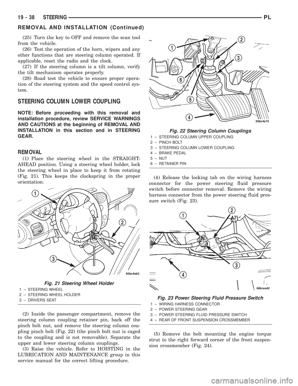
(1) Place the steering wheel in the STRAIGHT-
AHEAD position. Using a steering wheel holder, lock
the steering wheel in place to keep it from rotating
(Fig. 21). This keeps the clockspring in the proper
orientation.
(2) Inside the passenger compartment, remove the
steering column coupling retainer pin, back off the
pinch bolt nut, and remove the steering column cou-
pling pinch bolt (Fig. 22) (the pinch bolt nut is caged
to the coupling and is not removable). Separate the
upper and lower steering column couplings.
(3) Raise the vehicle. Refer to HOISTING in the
LUBRICATION AND MAINTENANCE group in this
service manual for the correct lifting procedure.(4) Release the locking tab on the wiring harness
connector for the power steering fluid pressure
switch before connector removal. Remove the wiring
harness connector from the power steering fluid pres-
sure switch (Fig. 23).
(5) Remove the bolt mounting the engine torque
strut to the right forward corner of the front suspen-
sion crossmember (Fig. 24).
Fig. 21 Steering Wheel Holder
1 ± STEERING WHEEL
2 ± STEERING WHEEL HOLDER
3 ± DRIVERS SEAT
Fig. 22 Steering Column Couplings
1 ± STEERING COLUMN UPPER COUPLING
2 ± PINCH BOLT
3 ± STEERING COLUMN LOWER COUPLING
4 ± BRAKE PEDAL
5 ± NUT
6 ± RETAINER PIN
Fig. 23 Power Steering Fluid Pressure Switch
1 ± WIRING HARNESS CONNECTOR
2 ± POWER STEERING GEAR
3 ± POWER STEERING FLUID PRESSURE SWITCH
4 ± REAR OF FRONT SUSPENSION CROSSMEMBER
19 - 38 STEERINGPL
REMOVAL AND INSTALLATION (Continued)
Page 1233 of 1285
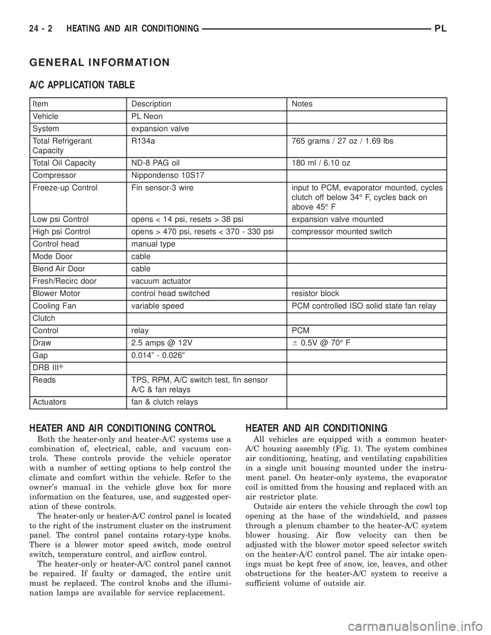
GENERAL INFORMATION
A/C APPLICATION TABLE
Item Description Notes
Vehicle PL Neon
System expansion valve
Total Refrigerant
CapacityR134a 765 grams / 27 oz / 1.69 lbs
Total Oil Capacity ND-8 PAG oil 180 ml / 6.10 oz
Compressor Nippondenso 10S17
Freeze-up Control Fin sensor-3 wire input to PCM, evaporator mounted, cycles
clutch off below 34É F, cycles back on
above 45É F
Low psi Control opens < 14 psi, resets > 38 psi expansion valve mounted
High psi Control opens > 470 psi, resets < 370 - 330 psi compressor mounted switch
Control head manual type
Mode Door cable
Blend Air Door cable
Fresh/Recirc door vacuum actuator
Blower Motor control head switched resistor block
Cooling Fan variable speed PCM controlled ISO solid state fan relay
Clutch
Control relay PCM
Draw 2.5 amps @ 12V60.5V @ 70É F
Gap 0.014º - 0.0269
DRB IIIT
Reads TPS, RPM, A/C switch test, fin sensor
A/C & fan relays
Actuators fan & clutch relays
HEATER AND AIR CONDITIONING CONTROL
Both the heater-only and heater-A/C systems use a
combination of, electrical, cable, and vacuum con-
trols. These controls provide the vehicle operator
with a number of setting options to help control the
climate and comfort within the vehicle. Refer to the
owner's manual in the vehicle glove box for more
information on the features, use, and suggested oper-
ation of these controls.
The heater-only or heater-A/C control panel is located
to the right of the instrument cluster on the instrument
panel. The control panel contains rotary-type knobs.
There is a blower motor speed switch, mode control
switch, temperature control, and airflow control.
The heater-only or heater-A/C control panel cannot
be repaired. If faulty or damaged, the entire unit
must be replaced. The control knobs and the illumi-
nation lamps are available for service replacement.
HEATER AND AIR CONDITIONING
All vehicles are equipped with a common heater-
A/C housing assembly (Fig. 1). The system combines
air conditioning, heating, and ventilating capabilities
in a single unit housing mounted under the instru-
ment panel. On heater-only systems, the evaporator
coil is omitted from the housing and replaced with an
air restrictor plate.
Outside air enters the vehicle through the cowl top
opening at the base of the windshield, and passes
through a plenum chamber to the heater-A/C system
blower housing. Air flow velocity can then be
adjusted with the blower motor speed selector switch
on the heater-A/C control panel. The air intake open-
ings must be kept free of snow, ice, leaves, and other
obstructions for the heater-A/C system to receive a
sufficient volume of outside air.
24 - 2 HEATING AND AIR CONDITIONINGPL