wiper fluid DODGE NEON 2000 Service Repair Manual
[x] Cancel search | Manufacturer: DODGE, Model Year: 2000, Model line: NEON, Model: DODGE NEON 2000Pages: 1285, PDF Size: 29.42 MB
Page 305 of 1285

WINDSHIELD WASHER SYSTEM
TABLE OF CONTENTS
page page
DESCRIPTION AND OPERATION
WINDSHIELD WASHER NOZZLE(S)............8
WINDSHIELD WASHER SYSTEM.............8
DIAGNOSIS AND TESTING
WINDSHIELD WASHER SYSTEM.............9REMOVAL AND INSTALLATION
WINDSHIELD WASHER HOSE................9
WINDSHIELD WASHER NOZZLES.............9
WINDSHIELD WASHER RESERVOIR..........10
WINDSHIELD WASHER PUMP...............10
DESCRIPTION AND OPERATION
WINDSHIELD WASHER NOZZLE(S)
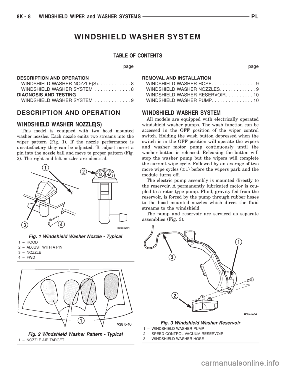
This model is equipped with two hood mounted
washer nozzles. Each nozzle emits two streams into the
wiper pattern (Fig. 1). If the nozzle performance is
unsatisfactory they can be adjusted. To adjust insert a
pin into the nozzle ball and move to proper pattern (Fig.
2). The right and left nozzles are identical.
WINDSHIELD WASHER SYSTEM
All models are equipped with electrically operated
windshield washer pumps. The wash function can be
accessed in the OFF position of the wiper control
switch. Holding the wash button depressed when the
switch is in the OFF position will operate the wipers
and washer motor pump continuously until the
washer button is released. Releasing the button will
stop the washer pump but the wipers will complete
the current wipe cycle. Followed by an average of two
more wipe cycles (61) before the wipers park and the
module turns off.
The electric pump assembly is mounted directly to
the reservoir. A permanently lubricated motor is cou-
pled to a rotor type pump. Fluid, gravity fed from the
reservoir, is forced by the pump through rubber hoses
to the hood mounted nozzles which direct the fluid
streams to the windshield.
The pump and reservoir are serviced as separate
assemblies (Fig. 3).
Fig. 1 Windshield Washer Nozzle - Typical
1 ± HOOD
2 ± ADJUST WITH A PIN
3 ± NOZZLE
4 ± FWD
Fig. 2 Windshield Washer Pattern - Typical
1 ± NOZZLE AIR TARGET
Fig. 3 Windshield Washer Reservoir
1 ± WINDSHIELD WASHER PUMP
2 ± SPEED CONTROL VACUUM RESERVOIR
3 ± WINDSHIELD WASHER HOSE
8K - 8 WINDSHIELD WIPER and WASHER SYSTEMSPL
Page 306 of 1285

DIAGNOSIS AND TESTING
WINDSHIELD WASHER SYSTEM
Whenever a windshield washer malfunction occurs,
first verify that the windshield washer wire harnessis properly connected to all connectors before starting
normal diagnosis and repair procedures. Refer to
Windshield Washer System Test table.
WINDSHIELD WASHER SYSTEM TEST
CONDITION POSSIBLE CAUSE CORRECTION
PUMP RUNS NO FLUID
FLOWING.1. NO FLUID IN THE
RESERVOIR.
2. NOZZLE PLUGGED
OR FROZEN.
3. BROKEN, LOOSE OR
PINCHED HOSE.
4. FAULTY PUMP.1. FILL RESERVOIR.
2. THAW AND CHECK FLOW IF BLOCKED
3. CHECK FLOW THROUGH HOSE CONNECTIONS.
4. APPLY BATTERY VOLTAGE TO MOTOR
TERMINALS, REPLACE IF PUMP DOES NOT RUN.
SYSTEM OPERATES
INTERMITTENTLY.1. LOOSE WIRE
CONNECTION.
2. FAULTY SWITCH.1. CHECK WIRE CONNECTIONS.
2. DISCONNECT WIRE HARNESS USE
VOLTMETER TO CHECK SWITCH.
SYSTEM OUTPUT IS
LOW.1. PINCHED HOSE.
2. HOSE BLOCKED.1. CHECK FLOW THROUGH HOSE CONNECTION.
2. DISCONNECT HOSE AT NOZZLE AND Y
CONNECTOR CHECK FOR FLOW. REPLACE ASS
NECESSARY.
REMOVAL AND INSTALLATION
WINDSHIELD WASHER HOSE
REMOVAL
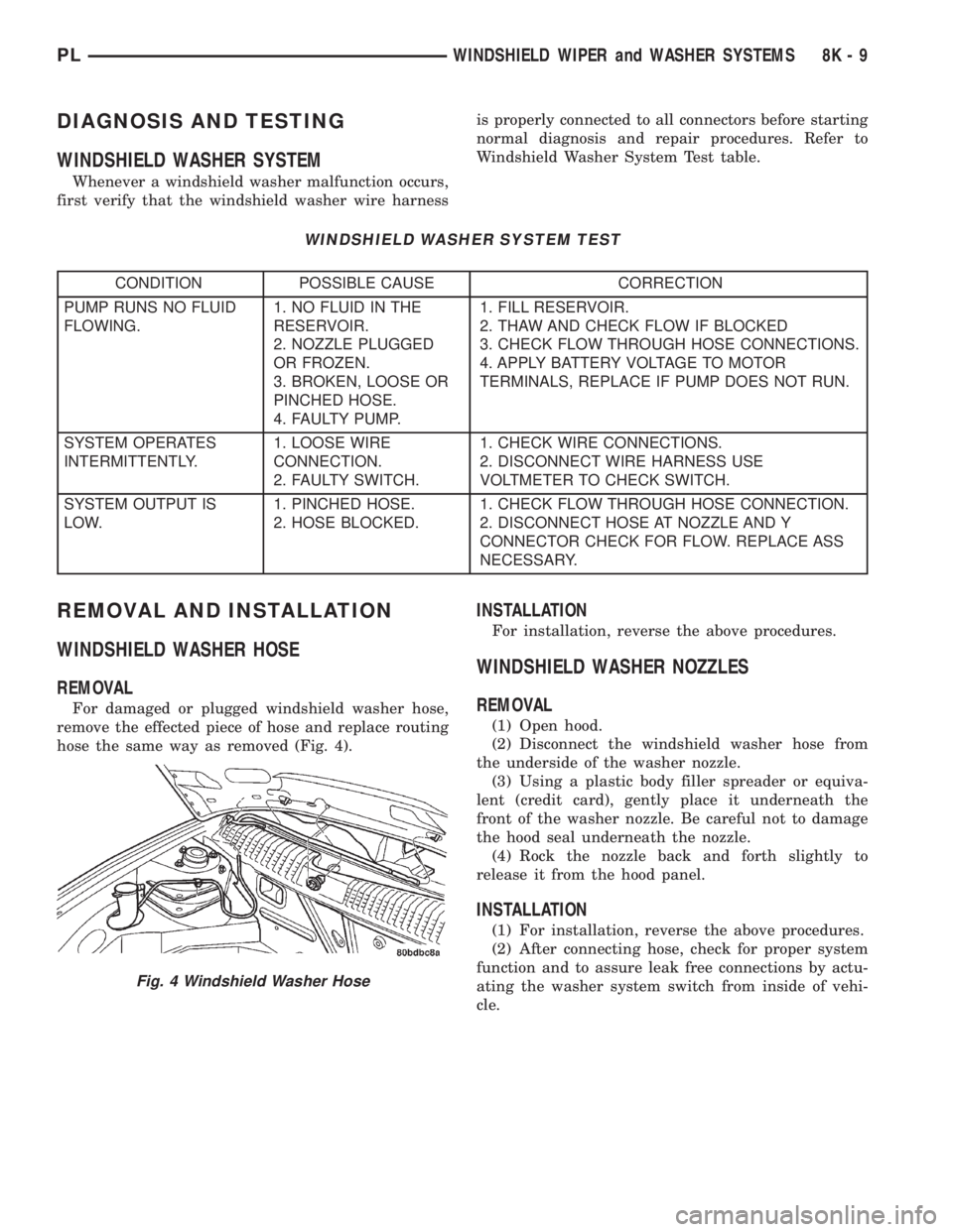
For damaged or plugged windshield washer hose,
remove the effected piece of hose and replace routing
hose the same way as removed (Fig. 4).
INSTALLATION
For installation, reverse the above procedures.
WINDSHIELD WASHER NOZZLES
REMOVAL
(1) Open hood.
(2) Disconnect the windshield washer hose from
the underside of the washer nozzle.
(3) Using a plastic body filler spreader or equiva-
lent (credit card), gently place it underneath the
front of the washer nozzle. Be careful not to damage
the hood seal underneath the nozzle.
(4) Rock the nozzle back and forth slightly to
release it from the hood panel.
INSTALLATION
(1) For installation, reverse the above procedures.
(2) After connecting hose, check for proper system
function and to assure leak free connections by actu-
ating the washer system switch from inside of vehi-
cle.
Fig. 4 Windshield Washer Hose
PLWINDSHIELD WIPER and WASHER SYSTEMS 8K - 9
Page 909 of 1285

(25) Turn the key to OFF and remove the scan tool
from the vehicle.
(26) Test the operation of the horn, wipers and any
other functions that are steering column operated. If
applicable, reset the radio and the clock.
(27) If the steering column is a tilt column, verify
the tilt mechanism operates properly.
(28) Road test the vehicle to ensure proper opera-
tion of the steering system and the speed control sys-
tem.
STEERING COLUMN LOWER COUPLING
NOTE: Before proceeding with this removal and
installation procedure, review SERVICE WARNINGS
AND CAUTIONS at the beginning of REMOVAL AND
INSTALLATION in this section and in STEERING
GEAR.
REMOVAL
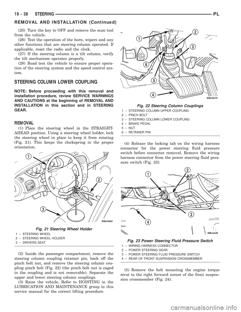
(1) Place the steering wheel in the STRAIGHT-
AHEAD position. Using a steering wheel holder, lock
the steering wheel in place to keep it from rotating
(Fig. 21). This keeps the clockspring in the proper
orientation.
(2) Inside the passenger compartment, remove the
steering column coupling retainer pin, back off the
pinch bolt nut, and remove the steering column cou-
pling pinch bolt (Fig. 22) (the pinch bolt nut is caged
to the coupling and is not removable). Separate the
upper and lower steering column couplings.
(3) Raise the vehicle. Refer to HOISTING in the
LUBRICATION AND MAINTENANCE group in this
service manual for the correct lifting procedure.(4) Release the locking tab on the wiring harness
connector for the power steering fluid pressure
switch before connector removal. Remove the wiring
harness connector from the power steering fluid pres-
sure switch (Fig. 23).
(5) Remove the bolt mounting the engine torque
strut to the right forward corner of the front suspen-
sion crossmember (Fig. 24).
Fig. 21 Steering Wheel Holder
1 ± STEERING WHEEL
2 ± STEERING WHEEL HOLDER
3 ± DRIVERS SEAT
Fig. 22 Steering Column Couplings
1 ± STEERING COLUMN UPPER COUPLING
2 ± PINCH BOLT
3 ± STEERING COLUMN LOWER COUPLING
4 ± BRAKE PEDAL
5 ± NUT
6 ± RETAINER PIN
Fig. 23 Power Steering Fluid Pressure Switch
1 ± WIRING HARNESS CONNECTOR
2 ± POWER STEERING GEAR
3 ± POWER STEERING FLUID PRESSURE SWITCH
4 ± REAR OF FRONT SUSPENSION CROSSMEMBER
19 - 38 STEERINGPL
REMOVAL AND INSTALLATION (Continued)